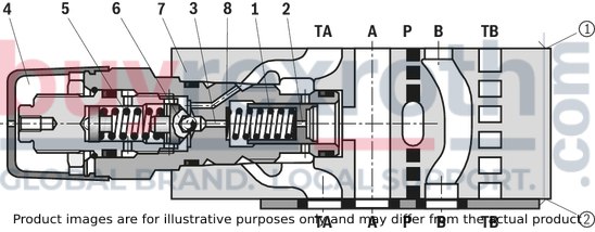
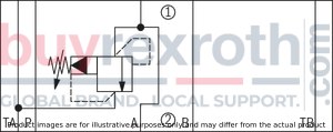
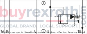
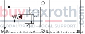
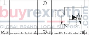
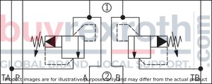
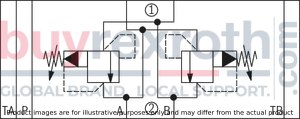
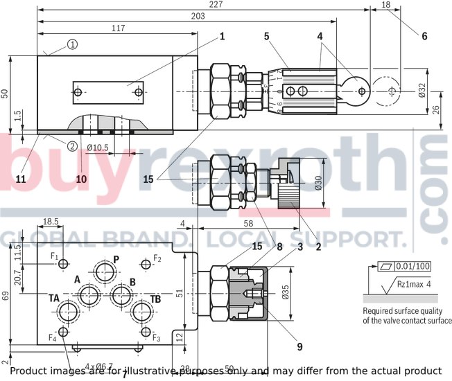
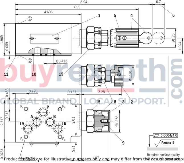
Version "VA", "VP" and "VT"
(dimensions im mm)
Dimensions in mm

|
1
|
Name plate
|
|
2
|
Adjustment type "1"
|
|
3
|
Adjustment type "2" (with version "J3" and "J5" without protective cap)
|
|
4
|
Adjustment type "3"
|
|
5
|
Adjustment type "7"
|
|
6
|
Dimensions required to remove the key
|
|
7
|
Valve mounting bores
|
|
8
|
Lock nut SW24
|
|
9
|
Hexagon SW10
|
|
10
|
Identical seal rings for ports A, B, P, TA, TB (plate side)
|
|
11
|
Sealing plate 80 x 70 x 1.5 mm (only with version “VA” and “VP”)
|
|
12
|
Countersinks (only with version “VT”)
|
|
13
|
Versions “VA” and “VP”
|
|
14
|
Version “VT”
|
|
15
|
Hexagon SW30, tightening torque MA = 50 Nm
|
|
➀
|
component side – Porting pattern according to ISO 4401-05-04-0-05
|
|
➁
|
plate side – Porting pattern according to ISO 4401-05-04-0-05
|
|
Type
|
B1
|
B2
|
B3
|
H
|
L1
|
L2
|
L3
|
L4
|
L5
|
L6
|
L7
|
|
mm
|
mm
|
mm
|
mm
|
mm
|
mm
|
mm
|
mm
|
mm
|
mm
|
mm
|
|
VA/VP
|
69
|
11.5
|
20.7
|
26
|
227
|
203
|
117
|
57.6
|
50.3
|
4
|
45.5
|
|
VT
|
70
|
12
|
27
|
25
|
218
|
194
|
105
|
60.9
|
53.6
|
0.7
|
32.5
|
Version "VB"
(dimensions im mm)
Dimensions in mm

|
1
|
Name plate
|
|
2
|
Adjustment type "1"
|
|
3
|
Adjustment type "2" (with version "J3" and "J5" without protective cap)
|
|
4
|
Adjustment type "3"
|
|
5
|
Adjustment type "7"
|
|
6
|
Dimensions required to remove the key
|
|
7
|
Valve mounting bores
|
|
8
|
Lock nut SW24
|
|
9
|
Hexagon SW10
|
|
10
|
Identical seal rings for ports A, B, P, TA, TB (plate side)
|
|
11
|
Sealing plate 80 x 70 x 1.5 mm (only with version “VA” and “VP”)
|
|
15
|
Hexagon SW30, tightening torque MA = 50 Nm
|
|
➀
|
component side – Porting pattern according to ISO 4401-05-04-0-05
|
|
➁
|
plate side – Porting pattern according to ISO 4401-05-04-0-05
|
Version “VC” and “VD”
(dimensions in mm)
Dimensions in mm

|
1
|
Name plate
|
|
2
|
Adjustment type "1"
|
|
3
|
Adjustment type "2" (with version "J3" and "J5" without protective cap)
|
|
4
|
Adjustment type "3"
|
|
5
|
Adjustment type "7"
|
|
6
|
Dimensions required to remove the key
|
|
7
|
Valve mounting bores
|
|
8
|
Lock nut SW24
|
|
9
|
Hexagon SW10
|
|
10
|
Identical seal rings for ports A, B, P, TA, TB (plate side)
|
|
15
|
Hexagon SW30, tightening torque MA = 50 Nm
|
|
➀
|
component side – Porting pattern according to ISO 4401-05-04-0-05
|
|
➁
|
plate side – Porting pattern according to ISO 4401-05-04-0-05
|
|
Type
|
L1
|
L2
|
L3
|
L4
|
L5
|
L6
|
L7
|
L8
|
L9
|
L10
|
L11
|
|
mm
|
mm
|
mm
|
mm
|
mm
|
mm
|
mm
|
mm
|
mm
|
mm
|
mm
|
|
VC
|
123
|
111
|
112
|
89
|
90
|
59
|
60
|
52
|
53
|
2
|
1
|
|
VD
|
132
|
107
|
112
|
85
|
90
|
56
|
56
|
49
|
49
|
6
|
6
|
Notices:
To port X and Y bored according to ISO 4401-05-05-0-05 (e.g. for pilot-operated directional valve NG10), version “SO30“ applies at the end of the ordering code! Deviating from ISO 4401, port T is referred to with TA and port T1 is referred to with TB in this data sheet.
Valve mounting screws (separate order)
Version "J3"
4 hexagon socket head cap screws ISO 4762 - M6 - 10.9-CM-Fe-ZnNi-5-Cn-T0-H-B
friction coefficient µtotal = 0,09 … 0.14
Version "J5"
4 hexagon socket head cap screws ISO 4762 - M6 - 10.9-CM-Fe-ZnNi-8-Cn-T0-H-B
Friction coefficient µtotal = 0,09 … 0.14
Without corrosion protection
4 hexagon socket head cap screws ISO 4762 - M6 - 10.9
Friction coefficient µtotal = 0.12 … 0.17
Notice:
Length and tightening torque of the valve mounting screws must be calculated according to the components mounted under and over the sandwich plate valve.
Type Z2DB 10 VC and VD
Dimensions in mm

Type ZDB 10 VA, VP and VT
Dimensions in mm

Type ZDB 10 VA, VP and VT
Dimensions in mm


