


Z2DB10VD3-4X/315
Manufacturer: Bosch Rexroth
Material #: R978895588
Model : Z2DB10VD3-4X/315
$913.00 USD
More are expected on July 31, 2025
Status: This product is temporarily out of stock.
Qty: Delivered as early as July 31, 2025 when ordered in
This product is eligible for factory repair.
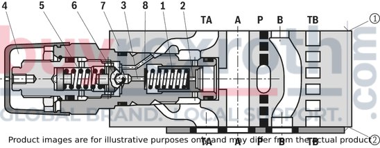
Pressure valves of type ZDB and Z2DB are pilot-operated pressure relief valves in sandwich plate design. They are used for limiting a system pressure. The valves basically consist of the housing (7) and one or two pressure valve cartridges. The system pressure can be set via the adjustment type (4).
In the initial position the valves are closed. The pressure in channel A acts on the spool (1). At the same time, pressure is applied to the spring-loaded side of the spool (1) via nozzle (2) and to the pilot poppet (6) via nozzle (3).
If the pressure in channel A exceeds the value set at the spring (5), the pilot poppet (6) opens. Hydraulic fluid flows from the spring-loaded side of the spool (1), nozzle (3) and channel (8) into channel T (TA). The resulting pressure drop moves the spool (1) and opens the connection from A to T (TA). In channel A, the pressure set at the spring (5) settles.
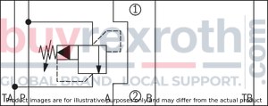
Type ZDB 10 VA2-4X/…V
➀ = component side
➁ = plate side
(measured with HLP46, ϑOil = 40 ±5 °C)
pE-qV characteristic curves

pE-qV characteristic curves

pE min-qV characteristic curves

pE min-qV characteristic curves

Notice:
The characteristic curves apply to the pressure at the valve output p = 0 bar across the entire flow range.
Type ZDB 10 VA…

Type ZDB 10 VB…

Type ZDB 10 VP…
Type ZDB 10 VT…

Type Z2DB 10 VC…
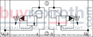
Type Z2DB 10 VD…
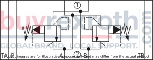
➀ = component side
➁ = plate side
Notice:
Deviating from ISO 4401, port T is referred to with TA and port T1 is referred to with TB in this data sheet.
Version "VA", "VP" and "VT"
(dimensions im mm)
Dimensions in mm

|
1 |
Name plate |
|
2 |
Adjustment type "1" |
|
3 |
Adjustment type "2" (with version "J3" and "J5" without protective cap) |
|
4 |
Adjustment type "3" |
|
5 |
Adjustment type "7" |
|
6 |
Dimensions required to remove the key |
|
7 |
Valve mounting bores |
|
8 |
Lock nut SW24 |
|
9 |
Hexagon SW10 |
|
10 |
Identical seal rings for ports A, B, P, TA, TB (plate side) |
|
11 |
Sealing plate 80 x 70 x 1.5 mm (only with version “VA” and “VP”) |
|
12 |
Countersinks (only with version “VT”) |
|
13 |
Versions “VA” and “VP” |
|
14 |
Version “VT” |
|
15 |
Hexagon SW30, tightening torque MA = 50 Nm |
|
➀ |
component side – Porting pattern according to ISO 4401-05-04-0-05 |
|
➁ |
plate side – Porting pattern according to ISO 4401-05-04-0-05 |
|
Type |
B1 |
B2 |
B3 |
H |
L1 |
L2 |
L3 |
L4 |
L5 |
L6 |
L7 |
|
mm |
mm |
mm |
mm |
mm |
mm |
mm |
mm |
mm |
mm |
mm |
|
| VA/VP | 69 | 11.5 | 20.7 | 26 | 227 | 203 | 117 | 57.6 | 50.3 | 4 | 45.5 |
| VT | 70 | 12 | 27 | 25 | 218 | 194 | 105 | 60.9 | 53.6 | 0.7 | 32.5 |
Version "VB"
(dimensions im mm)
Dimensions in mm
|
1 |
Name plate |
|
2 |
Adjustment type "1" |
|
3 |
Adjustment type "2" (with version "J3" and "J5" without protective cap) |
|
4 |
Adjustment type "3" |
|
5 |
Adjustment type "7" |
|
6 |
Dimensions required to remove the key |
|
7 |
Valve mounting bores |
|
8 |
Lock nut SW24 |
|
9 |
Hexagon SW10 |
|
10 |
Identical seal rings for ports A, B, P, TA, TB (plate side) |
|
11 |
Sealing plate 80 x 70 x 1.5 mm (only with version “VA” and “VP”) |
|
15 |
Hexagon SW30, tightening torque MA = 50 Nm |
|
➀ |
component side – Porting pattern according to ISO 4401-05-04-0-05 |
|
➁ |
plate side – Porting pattern according to ISO 4401-05-04-0-05 |
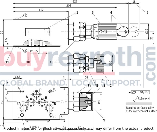
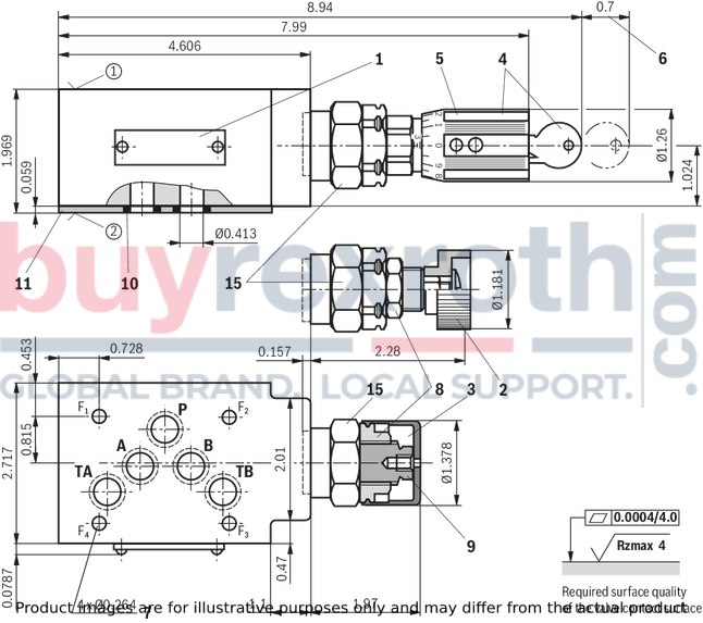
Version “VC” and “VD”
(dimensions in mm)
Dimensions in mm

|
1 |
Name plate |
|
2 |
Adjustment type "1" |
|
3 |
Adjustment type "2" (with version "J3" and "J5" without protective cap) |
|
4 |
Adjustment type "3" |
|
5 |
Adjustment type "7" |
|
6 |
Dimensions required to remove the key |
|
7 |
Valve mounting bores |
|
8 |
Lock nut SW24 |
|
9 |
Hexagon SW10 |
|
10 |
Identical seal rings for ports A, B, P, TA, TB (plate side) |
|
15 |
Hexagon SW30, tightening torque MA = 50 Nm |
|
➀ |
component side – Porting pattern according to ISO 4401-05-04-0-05 |
|
➁ |
plate side – Porting pattern according to ISO 4401-05-04-0-05 |
|
Type |
L1 |
L2 |
L3 |
L4 |
L5 |
L6 |
L7 |
L8 |
L9 |
L10 |
L11 |
|
mm |
mm |
mm |
mm |
mm |
mm |
mm |
mm |
mm |
mm |
mm |
|
| VC | 123 | 111 | 112 | 89 | 90 | 59 | 60 | 52 | 53 | 2 | 1 |
| VD | 132 | 107 | 112 | 85 | 90 | 56 | 56 | 49 | 49 | 6 | 6 |
Notices:
To port X and Y bored according to ISO 4401-05-05-0-05 (e.g. for pilot-operated directional valve NG10), version “SO30“ applies at the end of the ordering code! Deviating from ISO 4401, port T is referred to with TA and port T1 is referred to with TB in this data sheet.
Valve mounting screws (separate order)
Version "J3"4 hexagon socket head cap screws ISO 4762 - M6 - 10.9-CM-Fe-ZnNi-5-Cn-T0-H-B
friction coefficient µtotal = 0,09 … 0.14
Version "J5"
4 hexagon socket head cap screws ISO 4762 - M6 - 10.9-CM-Fe-ZnNi-8-Cn-T0-H-B
Friction coefficient µtotal = 0,09 … 0.14
Without corrosion protection
4 hexagon socket head cap screws ISO 4762 - M6 - 10.9
Friction coefficient µtotal = 0.12 … 0.17
Notice:
Length and tightening torque of the valve mounting screws must be calculated according to the components mounted under and over the sandwich plate valve.
Type Z2DB 10 VC and VD
Dimensions in mm

| 1) | Fit |
Type ZDB 10 VA, VP and VT
Dimensions in mm
| 1) | Fit |
Type ZDB 10 VA, VP and VT
Dimensions in mm

Related Products
R900712652
$28.55 USD
R900909209
$680.00 USD
R900371450
$898.00 USD
R901259515
$531.00 USD
R901112178
$1,273.00 USD


