


AXIAL-PISTON PUMP A17FO063/10NLWK0E81-0
Manufacturer: Bosch Rexroth
Material #: R902162394
Model : A17FO063/10NLWK0E81-0
***Disclaimer: The following summary contains information gathered from various sources such as product descriptions, technical specifications and catalogs. While efforts have been made to provide accurate details, inaccuracies may occur. It is advised to verify all information by contacting Bosch Rexroth directly.***
The Bosch Rexroth A17FO063/10NLWK0E81-0 (R902162394) is an axial piston pump of the AFO series, designed specifically for open circuit applications in commercial vehicles. This fixed displacement unit operates under medium pressure and is optimized for direct mounting on power takeoffs, making it suitable for a variety of vehicles such as street tippers, dump trucks, HGV loading cranes, tankers, and municipal vehicles. With a displacement size of 63 cm³ and a nominal pressure of 280 bar that can reach a maximum pressure of 350 bar, this pump ensures reliable performance.
The A17FO063/10NLWK0E81-0 is engineered to provide high total efficiency and a long service life due to its bent-axis design. It features a straightforward process for adjusting drive and rotational directions, enhancing its versatility. The diecast aluminum housing contributes to an optimized weight for better vehicle integration without compromising durability. Additionally, its design eliminates the need for a drain line at switching points.
This model boasts low operating noise levels and exceptional suction characteristics due to its well-designed port plate for service lines. The pump's flow rate is proportional to the drive speed and displacement, ensuring precise control over hydraulic functions. It comes with FKM fluorocarbon rubber seals and has splined shaft ends similar to DIN ISO standards.
The A17FO063/10NLWK0E81-0 does not require any external drain line connections, simplifying installation and maintenance. Its maximum rotational speed supports efficient operation while maintaining safety standards without the need for additional functions or connection threads beyond the metric system. This product showcases Bosch Rexroth's commitment to high-quality hydraulic solutions tailored for demanding commercial vehicle applications.

$3,913.00 USD
Availability: Backordered
Ships from US Note: Sales tax, shipping, and applicable tariffs will be calculated at checkout.
Qty:
Delivered as early as January 20, 2027

$4,108.65 USD
Availability: 2 In Stock
Ships from CA Note: Sales tax, shipping, and applicable tariffs will be calculated at checkout.
Qty:
Delivered as early as July 28, 2026
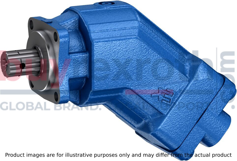
Table of values
|
Size |
23 | 32 | 45 | 63 | 80 | 107 | |||
|
Displacement |
Vg |
cm³ |
22.9 | 32 | 45.6 | 63 | 80.4 | 106.7 | |
|
Nominal pressure |
pnom |
bar |
350 | 350 | 350 | 350 | 350 | 350 | |
|
Maximum pressure |
pmax |
bar |
400 | 400 | 400 | 400 | 400 | 400 | |
|
Maximum speed |
nnom 1) |
rpm |
3050 | 2750 | 2650 | 2200 | 2150 | 2000 | |
|
nmax 2) |
rpm |
4300 | 3900 | 3800 | 3200 | 3100 | 2800 | ||
|
Flow |
at nnom |
qV |
l/min |
70 | 88 | 121 | 139 | 173 | 213 |
|
Power |
at nnom and pnom |
P |
kW |
41 | 51 | 71 | 81 | 101 | 124 |
|
Torque |
at pnom |
M |
Nm |
127 | 178 | 254 | 351 | 448 | 594 |
|
Rotary stiffness |
c |
kNm/rad |
2.56 | 3.12 | 4.18 | 6.25 | 8.73 | 11.2 | |
|
Moment of inertia for rotary group |
JTW |
kg·m² |
0.0012 | 0.0012 | 0.003 | 0.0042 | 0.0072 | 0.0116 | |
|
Maximum angular acceleration |
ɑ |
rad/s² |
6500 | 6500 | 14600 | 7500 | 6000 | 4500 | |
|
Case volume |
V |
l |
0.25 | 0.29 | 0.4 | 0.5 | 0.6 | 0.75 | |
|
Mass moment |
MG |
Nm |
4.7 | 4.7 | 8.6 | 9.9 | 15.3 | 20 | |
|
Weight (approx.) |
m |
kg |
5.9 | 5.9 | 8.4 | 9.3 | 12.3 | 15 | |
| 1) |
These values are valid at: - an absolute pressure of pabs = 1 bar at suction port S - for the optimum viscosity range from vopt = 36 to 16 mm2/s - with hydraulic fluid based on mineral oils |
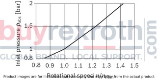
| 2) | Maximum speed (limiting speed) with increased inlet pressure pabs at suction port S, see the following diagram. |
Maximum speed
Note
The values in the table are theoretical values, without consideration of efficiencies and tolerances. The values are rounded. Exceeding the maximum or falling below the minimum permissible values can lead to a loss of function, a reduction in operational service life or total destruction of the axial piston unit. Other permissible limit values, such as speed variation, reduced angular acceleration as a function of the frequency and the permissible angular acceleration at start (lower than the maximum angular acceleration) can be found in data sheet 90261.|
Determining the operating characteristics |
||
|
Flow |

|
[l/min] |
|
Torque |

|
[Nm] |
|
Power |

|
[kW] |
|
Key |
|
|
Vg |
Displacement per revolution [cm3] |
|
Δp |
Differential pressure [bar] |
|
n |
Rotational speed [rpm] |
|
ηv |
Volumetric efficiency |
|
ηhm |
Hydraulic-mechanical efficiency |
|
ηt |
Total efficiency (ηt = ηv • ηhm) |
Hydraulic fluid
The axial piston unit is designed for operation with HLP mineral oil according to DIN 51524.
Application instructions and requirements for hydraulic fluids should be taken from the following data sheets before the start of project planning:
90220: Hydraulic fluids based on mineral oils and related hydrocarbons 90221: Environmentally acceptable hydraulic fluids 90222: Fire-resistant, water-free hydraulic fluids (HFDR, HFDU)
The axial piston unit is not suitable for operation with water-containing HF hydraulic fluids.
For operation with HFD hydraulic fluids please note limitations regarding technical data. Please contact us.
Viscosity and temperature of hydraulic fluids
|
|
Viscosity |
Temperature1) |
Comment |
|
Cold start |
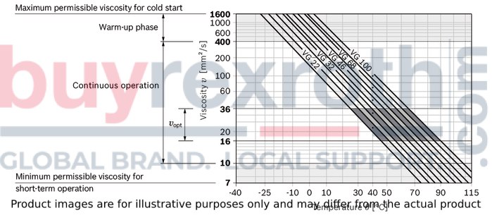
νmax ≤ 1600 mm²/s |
ϑSt ≥ -25 °C |
t ≤ 3 min, without load (p ≤ 50 bar), n ≤ 1000 rpm, |
|
Warm-up phase |
ν = 400 … 1600 mm²/s |
t ≤ 15 min, p ≤ 0.7 • pnom and n ≤ 0.5 • nnom |
|
|
Continuous operation |
ν = 10 … 400 mm²/s3) |
ϑ ≤ +103 °C |
measured at bleed port R |
|
νopt = 16 … 36 mm²/s |
range of optimum operating viscosity and efficiency |
||
|
Short-term operation |
νmin = 7 … 10 mm²/s |
ϑ ≤ +103 °C |
t ≤ 3 min, p ≤ 0.3 • pnom |
| 1) | If the specified temperatures cannot be maintained due to extreme operating parameters, please contact us. |
| 2) | The FKM shaft seal may be used for case drain temperatures from -25 °C to +115 °C. For the temperature range below -25 °C, please contact us. |
| 3) | Equates e.g. with the VG 46 a temperature range of +5 °C to +85 °C (see selection diagram) |
Explanatory note regarding the selection of hydraulic fluid
The hydraulic fluid should be selected such that the operating viscosity in the operating temperature range is within the optimum range (vopt see selection diagram).
Selection diagram
Filtration of the hydraulic fluid
Finer filtration improves the cleanliness level of the hydraulic fluid, which increases the service life of the axial piston unit.
A cleanliness level of at least 20/18/15 is to be maintained according to ISO 4406.
At a hydraulic fluid viscosity of less than 10 mm²/s (e.g. due to high temperatures in short-term operation) at the drain port, a cleanliness level of at least 19/17/14 according to ISO 4406 is required.
For example, the viscosity is 10 mm²/s at:
HLP 32 a temperature of 73°C HLP 46 a temperature of 85°COperating pressure range
|
Pressure at working port A or B (high-pressure side) |
Definition |
||
|
Nominal pressure |
pnom |
350 bar |
The nominal pressure corresponds to the maximum design pressure. |
|
Maximum pressure |
pmax |
400 bar |
The maximum pressure corresponds to the maximum operating pressure within the single operating period. The sum of the single operating periods must not exceed the total operating period. |
|
Single operating period |
5 s |
||
|
Total operating period |
50 h |
||
|
Minimum pressure |
pHP min |
10 bar |
Minimum pressure on high-pressure side (port A or B) required to prevent damage to the axial piston unit. |
|
Rate of pressure change |
RA max |
9000 bar/s |
Maximum permissible rate of pressure build-up and reduction during a pressure change over the entire pressure range. |
|
Pressure at suction port S (inlet) |
Definition |
||
|
Minimum pressure |
ps min |
0.8 bar absolute |
Minimum pressure at inlet (suction port S) that is required to avoid damage to the axial piston unit. The minimum required pressure is dependent on the speed of the axial piston unit. |
|
Maximum pressure |
ps max |
2 bar absolute |
|
Note
Working pressure range valid when using hydraulic fluids based on mineral oils. Values for other hydraulic fluids, please contact us.Pressure definition
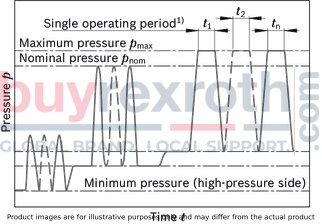
| 1) | Total operating period = t1 + t2 + ... + tn |
Rate of pressure change

Permissible axial forces of the drive shaft
|
Size |
23 | 32 | 45 | 63 | 80 | 107 | |||
|
Maximum axial force, when standstill or in non-pressurized conditions |

|
+ Fax max |
N |
0 | |||||
|
- Fax max |
N |
24 | 33 | 43 | 53 | 60 | 71 | ||
Notes
The values given are maximum values and do not apply to continuous operation. The axial force in direction Faxmust be avoided as this would reduce the bearing life service. Radial forces are not permissible.Direction of rotation
The direction of rotation of the axial piston unit is defined by means of a pressure nipple screwed into the service line port and can easily be changed.
By changing the pressure nipple, the service line port and the suction port are exchanged. This is e.g. required when mounting at a PTO with an counter-clockwise direction of rotation.
The process of converting the pressure nipple can be seen from the instruction manual (91520-01-B, chapter 6.4.2 “Direction of rotation and changing the direction of rotation”).
Direction of rotation on delivery
On delivery, the pressure nipple (1) is pre-assembled in the right service line port of the axial piston unit. The permissible drive direction of the pump looking at the drive shaft: counter-clockwise. The power take-off turns clockwise.
Note
The pressure nipple is pre-assembled on delivery and must be tightened to the torque specified for the thread size before installation (see instruction manual).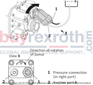
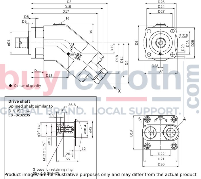
| 1) | Center bore according to DIN 332 (thread according to DIN 13) |
|
Size |
D1 |
D3 |
D4 |
D5 |
D6 |
D7 |
D8 |
D9 |
D11 |
D12 |
D13 |
D14 |
D15 |
D16 |
D17 |
D18 |
D19 |
D20 |
D21 |
D22 |
D23 |
D24 |
D25 |
D26 |
D27 |
D28 |
D29 |
|
mm |
mm |
mm |
mm |
mm |
mm |
mm |
mm |
mm |
mm |
mm |
mm |
mm |
mm |
mm |
mm |
mm |
mm |
mm |
mm |
mm |
mm |
mm |
mm |
mm |
mm |
mm |
|
| 23 | 80 | 185 | 103 | 58 | 105 | - | 15 | 9 | 43 | 25.8 | 81 | 88 | 173 | - | 159 | 76 | 88 | 91 | 88 | 51.8 | 0.7 | 96 | 105 | 107 | 80 | 80 | 13 |
| 32 | 80 | 185 | 103 | 58 | 105 | - | 15 | 9 | 43 | 25.8 | 81 | 88 | 173 | - | 159 | 76 | 88 | 91 | 88 | 51.8 | 0.7 | 96 | 105 | 107 | 80 | 80 | 13 |
| 45 | 80 | 223 | 119 | 63 | 108 | 103 | 15 | 9 | 43 | 29 | 104 | 102 | 210 | 132 | 194 | 89 | 108 | 108 | 108 | 58.8 | 0.8 | 96 | 105 | 107 | 80 | 80 | 13 |
| 63 | 80 | 232 | 126 | 63 | 108 | 103 | 15 | 9 | 43 | 32 | 109 | 110 | 219 | 132 | 203 | 96 | 108 | - | 108 | 64 | 0.8 | 96 | 105 | 107 | 80 | 80 | 13 |
| 80 | 80 | 261 | 140 | 67.5 | 121 | 114 | 15 | 9 | 43 | 36 | 127 | 120 | 245 | 118 | 227 | 105 | 117 | 124 | 117 | 69 | 1 | 96 | 105 | 107 | 80 | 80 | 13 |
| 107 | 80 | 272 | 149 | 73.5 | 133 | 120 | 15 | 9 | 43 | 41 | 136 | 129 | 256 | - | 238 | 114 | 129 | - | 129 | 77 | 1 | 96 | 105 | 107 | 80 | 80 | 13 |
Ports
|
Size |
23 | 32 | 45 | 63 | 80 | 107 | ||
|
A |
Working port |
Size |
G 1/2; 14 mm deep | G 3/4; 16 mm deep | G 1; 18 mm deep | |||
|
Standard |
DIN ISO 228 | |||||||
|
State on delivery |
With protective cover (must be connected) | |||||||
|
S |
Suction port |
Size |
G 3/4; 16 mm deep | G 1; 18 mm deep | G 1 1/4; 20 mm deep | |||
|
Standard |
DIN ISO 228 | |||||||
|
State on delivery |
With protective cover (must be connected) | |||||||
|
R |
Air bleed port |
Size |
M10 x 1; 8 mm deep | |||||
|
Standard 1) |
DIN 3852 | |||||||
|
State on delivery 2) |
Plugged | |||||||
| 1) | The spot face can be deeper than specified in the appropriate standard. |
| 2) | Unless otherwise specified. Other layouts on request. |
Installation instructions
General
During commissioning and operation, the axial piston unit must be filled with hydraulic fluid and air bled. This must also be observed following a relatively long standstill as the axial piston unit may drain back to the reservoir via the hydraulic lines. The pump housing is internally connected to the suction chamber. A separate drain line from the housing to the reservoir is not needed. To achieve favorable noise values, all connecting lines should be decoupled by using elastic elements and above-reservoir installation is to be avoided. In all operating conditions, the suction and drain lines must lead into the reservoir below the minimum fluid level. The permissible suction height hS results from the overall loss of pressure; it must not, however, be higher than hS max = 800 mm. The minimum suction pressure at port S must also not fall below 0,8 bar absolute during operation and during cold start.Installation position
See the following examples 1 to 4.
Further installation positions are possible upon request. Recommended installation position: 1 and 2.
Below-tank installation (standard)
Below-tank installation is at hand if the axial piston unit is installed below the minimum liquid level outside the tank.
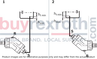
|
Installation position |
Air bleeding |
Filling |
|
1 |
R |
S |
|
2 |
‒ |
S |
Above-reservoir installation
Above-reservoir installation means that the axial piston unit is installed above the minimum fluid level of the reservoir.
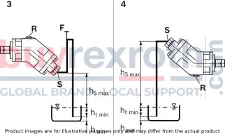
|
Installation position |
Air bleeding |
Filling |
|
3 |
R |
F |
|
4 |
S |
S |
|
Key |
|
|
F |
Filling / Air bleeding |
|
R |
Air bleed port |
|
S |
Suction port |
|
ht min |
Minimum required immersion depth (200 mm) |
|
hmin |
Minimum required spacing to reservoir bottom (100 mm) |
|
hS max |
Maximum permissible suction height (800 mm) |
Note
Connection F is part of the external piping and must be provided on the customer side to simplify the filling and bleeding.General project planning notes
The axial piston unit is designed to be used in open circuits. The project planning, installation and commissioning of the axial piston unit require the involvement of qualified skilled personnel. Before using the axial piston unit, please read the corresponding instruction manual completely and thoroughly. If necessary, request it from Bosch Rexroth. Before finalizing your design, request a binding installation drawing. The specified datas and notes must be observed. Preservation: Our axial piston units are supplied as standard with preservative protection for a maximum of 12 months. If longer preservative protection is required (maximum 24 months), please specify this in plain text when placing your order. The preservation times are valid under optimal storage conditions. Details of these conditions can be found in the data sheet 90312 or the instruction manual. A pressure relief valve is to be provided in the hydraulic system. Observe the instructions in the instruction manual regarding tightening torques of connection threads and other threaded joints used. The notes in the instruction manual on tightening torques of the port threads and other screw joints must be observed. The ports and fastening threads are designed for the permissible maximum pressure pmax (see instruction manual). The machine or system manufacturer must ensure that the connecting elements and lines correspond to the specified operating conditions (pressure, flow, hydraulic fluid, temperature) with the necessary safety factors. The working ports and function ports are designated only to accommodate hydraulic lines.Suction adapter
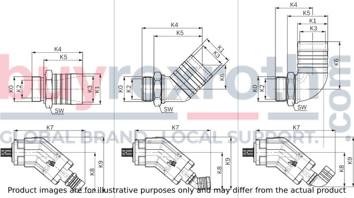
|
Pump size |
Version |
Hose |
Material number |
Thread K0 |
K1 |
K2 |
K3 |
K4 |
K5 |
K6 |
K7 |
K8 |
K9 |
SW |
|
mm |
mm |
mm |
mm |
mm |
mm |
mm |
mm |
mm |
mm |
|||||
| 23 | straight | 1 1/2" | R909831856 | G3/4 | 39 | 18 | 33.5 | 70 | 54 | - | 221 | 132 | 186 | 41 |
| 45° | 1 1/2" | R909831601 | G3/4 | 39 | 20 | 31 | 101 | 82 | 43 | 259 | 126 | 180 | 36 | |
| 90° | 1 1/2" | R909831602 | G3/4 | 39 | 20 | 31 | 62 | 43 | 81 | 265 | 117 | 171 | 36 | |
| 32 | straight | 1 1/2" | R909831856 | G3/4 | 39 | 18 | 33.5 | 70 | 54 | - | 221 | 132 | 186 | 41 |
| 45° | 1 1/2" | R909831601 | G3/4 | 39 | 20 | 31 | 101 | 82 | 43 | 259 | 126 | 180 | 36 | |
| 90° | 1 1/2" | R909831602 | G3/4 | 39 | 20 | 31 | 62 | 43 | 81 | 265 | 117 | 171 | 36 | |
| 45 | straight | 1 1/2" | R902600251 | G1 | 39 | 23.5 | 33.5 | 72 | 54 | - | 248 | 139 | 197 | 41 |
| 45° | 1 1/2" | R909831600 | G1 | 39 | 26 | 31 | 101 | 82 | 45 | 287 | 132 | 190 | 41 | |
| 90° | 1 1/2" | R909831599 | G1 | 39 | 26 | 31 | 64 | 44 | 85 | 296 | 127 | 185 | 41 | |
| 63 | straight | 1 1/2" | R902600251 | G1 | 39 | 23.5 | 33.5 | 72 | 54 | - | 257 | 146 | 204 | 41 |
| 2" | R902602028 | G1 | 51 | 26 | 44 | 82 | 64 | - | 268 | 157 | 215 | 55 | ||
| 45° | 1 1/2" | R909831600 | G1 | 39 | 26 | 31 | 101 | 82 | 45 | 296 | 139 | 197 | 41 | |
| 2" | R902602029 | G1 | 51 | 26 | 43 | 100 | 81 | 44 | 295 | 145 | 203 | 41 | ||
| 90° | 1 1/2" | R909831599 | G1 | 39 | 26 | 31 | 64 | 44 | 85 | 305 | 134 | 192 | 41 | |
| 2" | R902602030 | G1 | 51 | 26 | 43 | 62 | 42 | 81 | 305 | 138 | 196 | 41 | ||
| 80 | straight | 2" | R902600252 | G1 1/4 | 51 | 30 | 44 | 85 | 65 | - | 295 | 168 | 232 | 55 |
| 45° | 2" | R909831597 | G1 1/4 | 51 | 34 | 43 | 101 | 81 | 40 | 317 | 156 | 220 | 50 | |
| 90° | 2" | R909831598 | G1 1/4 | 51 | 35 | 43 | 63 | 43 | 80 | 330 | 144 | 208 | 50 | |
| 107 | straight | 2" | R902600252 | G1 1/4 | 51 | 30 | 44 | 85 | 65 | - | 306 | 177 | 245 | 55 |
| 2 1/2" | R902601630 | G1 1/4 | 63 | 31 | 54 | 82 | 64 | - | 308 | 180 | 248 | 65 | ||
| 45° | 2" | R909831597 | G1 1/4 | 51 | 34 | 43 | 101 | 81 | 40 | 328 | 165 | 234 | 50 | |
| 2 1/2" | R902601631 | G1 1/4 | 63 | 35 | 54 | 100 | 81 | 44 | 331 | 169 | 237 | 50 | ||
| 90° | 2" | R909831598 | G1 1/4 | 51 | 35 | 43 | 63 | 43 | 80 | 341 | 153 | 221 | 50 |
The suction adapter is not included in the scope of delivery and must be ordered separately.
Notes on suction line
Keep as short and straight as possible, without bend Use a supporting ring for plastic hoses Use two hose clamps to protect the suction hose against air suction Note pressure resistance of suction hose compared to ambient pressureReplacing seals
The O-rings used as seals to prevent air from entering the suction line are to be replaced after every removal and new installation in order to guarantee complete sealing.
Material number for O-rings
R909083796: O-ring for suction stud G3/4 R909083802: O-ring for suction stud G1 R909083808: O-ring for suction stud G1¼Coupling flange
There are special, modified coupling flanges in 4-hole and 6-hole design for the cardan shaft drive.
The coupling flange is not included in the scope of delivery and must be ordered separately.
4-hole coupling flange, complete – ⌀90 mm
Material number: R902060152

6-hole coupling flange, complete – ⌀100 mm
Material number: R902060153
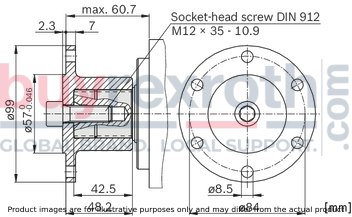
Notes
Assembly of the coupling flange is carried out by pulling onto the drive shaft with the aid of the threaded bore in the drive shaft end. The coupling flange must be clamped on the drive shaft using a socket-head screw. In addition, permanent lubrication should be applied between the drive shaft and the coupling flange. The socket-head screw should be secured in a suitable manner (e.g. gluing with Loctite 276) and tightened with a tightening torque of 130 Nm. Sudden axial impact upon the drive shaft will lead to rotary group damage and therefore must be strictly avoided.Related Products
R902162396
$4,332.00 USD
R902162394
$3,913.00 USD
R902230073
$2,854.00 USD
R902122693
$12,870.00 USD

R902294815
$8,156.00 USD