***Disclaimer: The following summary contains information gathered from various sources such as product descriptions, technical specifications and catalogs. While efforts have been made to provide accurate details, inaccuracies may occur. It is advised to verify all information by contacting Bosch Rexroth directly.***
The Bosch Rexroth ABZSS 20 M-3X/210E/S63V12 (R901409863) is a meticulously engineered hydraulic accumulator shutoff block designed to offer protection, isolation, and controlled unloading for hydraulic accumulators. This component is pivotal in maintaining the safety and effectiveness of hydraulic systems by preventing overpressure conditions which could lead to system failure or damage. It adheres to stringent regulations as set out by the Pressure Equipment Directive of the European Union, ensuring compliance with industry standards for safety and performance.
The connection to the hydraulic accumulator is facilitated through an accumulator adapter, providing a secure and reliable link between the two components. The ABZSS 20 M-3X/210E/S63V12 includes a pressure relief valve that serves as a safeguard against excessive pressure by allowing for pressure release when thresholds are exceeded. However, it's important to note that this valve is not intended for control purposes; its primary function is protective. Users must ensure there is an adequate margin between the maximum operating pressure and the working pressure to avoid unintended triggering of the relief valve.
With its series X designation, this shutoff block can withstand a maximum operating pressure that meets high industry demands while accommodating various nominal diameters including DN6, DN10, DN16, and DN25. This versatility allows it to be used across a range of applications requiring different flow rates and connection sizes. The Bosch Rexroth ABZSS 20 M-3X/210E/S63V12 (R901409863) thus represents a crucial component in hydraulic systems where accumulator performance and safety are paramount.
$1,587.00 USD
Availability: 4 In Stock
| Qty | Price | Savings |
|---|---|---|
| 5-24 | $1,547.32 USD | $39.68 USD |
| 25+ | $1,507.65 USD | $79.35 USD |
Qty: Delivered as early as November 18, 2025 when ordered in
Qty: Delivered as early as April 28, 2026 when ordered in
This product is eligible for factory repair.
Function
The accumulator shut-off block serves for the protection, isolation and unloading of hydraulic accumulators. It is classified based on its use according to the Pressure Equipment Directive 2014/68/EU article 4, section 3. The connection between the accumulator shut-off block and the accumulator is realized by means of an accumulator adapter.
The accumulator is protected from inadmissible overpressure by means of the pressure relief valve. The pressure relief valve must not be used for any control tasks. Sufficient difference between the maximum operating pressure and the working pressure must be ensured. Response of the pressure relief valve should be prevented, if possible.
Ordering code
|
01 |
02 |
03 |
04 |
05 |
06 |
07 |
08 |
09 |
10 |
11 |
12 |
13 |
14 |
||||
|
ABZSS |
‒ |
3X |
/ |
E |
/ |
‒ |
* |
|
Device designation |
||
|
01 |
Accumulator shut-off block |
ABZSS |
|
Type of connection |
||
|
02 |
Piping connection |
no code |
|
Subplate mounting |
-P1) |
|
|
Nominal diameter |
||
|
03 |
DN08 |
08 |
|
DN10 |
10 |
|
|
DN20 |
20 |
|
|
DN30 |
30 |
|
|
Unloading |
||
|
04 |
manual |
M |
|
manual and electro-magnetic (without manual override) |
E2) |
|
|
Component series |
||
|
05 |
Component series 30 ... 39 (30 ... 39: unchanged installation and connection dimensions) |
3X |
|
Pressure adjustment (others upon request) |
||
|
06 |
50 bar |
50 |
|
100 bar |
100 |
|
|
140 bar |
140 |
|
|
210 bar |
210 |
|
|
350 bar |
3503) |
|
|
Pressure relief valve |
||
|
07 |
Pressure relief valve, type-examination tested (with CE mark) 4) |
E |
|
Accumulator adapter |
||
|
08 |
Without accumulator adapter |
no code |
|
With BSP thread G1/2 |
||
|
DN08 |
S104 |
|
|
DN10; DN20 |
S30 |
|
|
With BSP thread G3/4 |
||
|
DN08 |
S108 |
|
|
DN10; DN20 |
S31 |
|
|
DN08 |
S105 |
|
|
DN10; DN20 |
S10 |
|
|
With BSP thread G1 1/4 |
||
|
DN08 |
S107 |
|
|
DN10; DN20 |
S12 |
|
|
DN30 |
S307 |
|
|
With BSP thread G2 |
||
|
DN08 |
S109 |
|
|
DN10; DN20 |
S13 |
|
|
DN30 |
S309 |
|
|
With SAE thread 3/4-16 UNF |
||
|
DN10; DN20 |
S64 |
|
|
With SAE thread 1 1/18-12 UN |
||
|
DN10; DN20 |
S60 |
|
|
With SAE thread 1 5/8-12 UN |
||
|
DN10; DN20 |
S62 |
|
|
DN30 |
S620 |
|
|
With SAE thread 1 7/8-12 UN |
||
|
DN10; DN20 |
S63 |
|
|
DN30 |
S630 |
|
|
Voltage type 5) |
||
|
09 |
Direct voltage 24 V |
G24 |
|
Alternating voltage 110 V |
G968) |
|
|
Alternating voltage 230 V |
G2058) |
|
|
Electrical connection 5) |
||
|
10 |
Without mating connector with protective cap |
K46) |
|
Seal material |
||
|
11 |
FKM seals |
V |
|
NBR seals |
W7) |
|
|
Connection thread |
||
|
12 |
BSP thread according to ISO 228 Part 1 |
no code |
|
SAE thread to ANSI B1.1 |
122) |
|
|
Special version |
||
|
13 |
DN30 with DBDS valve NG30 |
SO30 |
|
Shut-off device (2 positions) DN10 … DN30 |
103 |
|
|
Shut-off device (1 position) DN10 … DN30 |
104 |
|
|
Connection thread |
||
|
14 |
Further details in the plain text |
|
| 1) | Only “DN30” |
| 2) | Not with “DN08” |
| 3) | Type SO30 is supplied with a pressure rating of 315 bar |
| 4) | According to Pressure Equipment Directive 2014/68/EU |
| 5) | Only with electro-magnetic unloading design “E” |
| 6) | Mating connectors, separate order (data sheet 08006). |
| 7) | Special version |
| 8) | For connection to the AC voltage mains , a DC solenoid controlled via a rectifier is to be used (see table). For individual connection, a mating connector with integrated rectifier can be used (separate order). |
Notice:
Unlike the standard accumulator safety block, the ABZSS30 … SO30 is equipped with a direct operated pressure relief valve NG30.
Version ABZSS-P30 for subplate mounting.
|
AC voltage mains (admissible voltage tolerance ± 10%) |
Nominal voltage of the DC solenoid in case of operation with alternating voltage |
Ordering code |
|
110 V ‒ 50/60 Hz |
96 V |
G96 |
|
230 V ‒ 50/60 Hz |
205 V |
G205 |
general
|
Nominal diameter |
DN08 | DN10 | DN20 | DN30 | DN30SO30 | DNP30… | ||
|
Weight |
Version "M" |
kg |
4 | 5.2 | 8.5 | 20.5 | 26.5 | 33.1 |
|
Version "E" |
kg |
- | 5.5 | 8.8 | 20.8 | 26.8 | 33.4 | |
|
Ambient temperature range |
°C |
-15 … +80 | ||||||
hydraulic
|
Maximum operating pressure |
bar |
350 |
|
Hydraulic fluid temperature range |
°C |
-10 … +60 |
|
Seal material |
FKM seals or NBR seals (special version) | |
|
Block material |
Steel | |
|
Viscosity range |
mm²/s |
12 … 230 |
|
Maximum admissible degree of contamination of the hydraulic fluid, cleanliness class according to ISO 4406 (c) 1) |
Class 20/18/15 | |
| 1) | The cleanliness classes specified for the components must be adhered to in hydraulic systems. Effective filtration prevents faults and simultaneously increases the life cycle of the components. For the selection of the filters, see www.boschrexroth.com/filter. |
|
Hydraulic fluid |
Classification |
Suitable sealing materials |
Standards |
Data sheet |
|
|
Mineral oil |
HL, HLP, HLPD, HVLP, HVLPD |
FKM, NBR |
DIN 51524 |
90220 |
|
|
Bio-degradable |
Insoluble in water |
HETG |
FKM, NBR |
ISO 15380 |
90221 |
|
HEES |
FKM |
||||
|
Soluble in water |
HEPG |
FKM |
|||
| Important information on hydraulic fluids: | |
| ▶ For more information and data on the use of other hydraulic fluids, please refer to the data sheets above or contact us! | |
| ▶ There may be limitations regarding the technical valve data (temperature, pressure range, life cycle, maintenance intervals, etc.)! | |
| ▶ The ignition temperature of the hydraulic fluid used must be 40 K higher than the maximum solenoid surface temperature. | |
| ▶ Bio-degradable and flame-resistant: | |
| When using hydraulic fluids that are simultaneously zinc-solving, zinc may accumulate (700 mg zinc per pole tube). |
electrical
|
Protection class according to DIN EN 60529 1) |
With connector "K4" |
IP65 |
| 1) | With mating connector mounted and locked |
For applications outside these parameters, please consult us!
Type-examination tested safety valves type DBD1)
Size 6 (ABZSS 08, 10)

Size 10 (ABZSS 20)
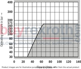
Size 20 (ABZSS 30, -P30)

Size 30 (ABZSS 30…SO30)

Notice:
Value pairs located in the areas of the characteristic curves with gray background cannot be realized with the safety valve. The characteristic curves shown here are only valid for a counter pressure of 0 bar in the discharge line.
1) Component series 1X, according to the Pressure Equipment Directive 2014/68/EU
Characteristic curves: Counter pressure in the discharge line
In principle, the valve should be operated without counter pressure in the discharge line, if possible. In case of counter pressure in the discharge line, the maximum possible flow is reduced. There is a relationship between maximum counter pressure pT in the discharge line and flow qV, which can be seen from the following characteristic curve. Characteristic curves for intermediate values of the response pressure which are not listed must be determined by means of interpolation.
When the flow approaches zero, the maximum counter pressure pT is in each case 10% of the response pressure. With increasing flow, the maximum counter pressure pT decreases.
Interpolation of intermediate values from the diagram
At the axis pT, mark 1/10 of the value of pA. Determine the next lower and the next higher characteristic curve for this point. The point marked at pT divides the section between lower and higher characteristic curve on the pT axis with a certain percentage. At the qVmax axis, divide the section between next lower and next higher characteristic curve in the same percentage as the section at the pT axis. From the zero position flow on the qVmax axis determined in that way, draw a straight line to the value on the pT axis marked before. Mark the system flow to be secured at the qVmax axis. Read off the maximum counter pressure for this value using the line at the pT axis drawn before.Characteristic curves: Counter pressure in the discharge line – size 6
Diagram for determining the maximum counter pressure pT in the discharge line at port T of the valve dependent on the flow qVmax for valves DBDS 6...1X/...E with different response pressures pA.
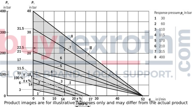
|
Characteristic curves |
Response pressurepA in bar |
|
1 |
30 |
|
2 |
60 |
|
3 |
110 |
|
4 |
115 |
|
5 |
170 |
|
6 |
210 |
|
7 |
315 |
|
8 |
400 |
|
Characteristic curves for intermediate values can be generated by interpolation. See "Counter pressure in the discharge line". |
|
pA Response pressure in bar
pT Maximum counter pressure in the discharge line (port T) in bar
qVmax Maximum flow in l/min
Area I Interpolation area I, for valves with pA = 30 … 110 bar and qVmax = 14 … 27 l/min
Area II Interpolation area II, for valves with pA = 115 … 400 bar and qVmax = 52 l/min
Determination of the maximum counter pressure
Example 1 (with already existing characteristic curve): Flow of the system/accumulator that has to be secured: qVmax = 15 l/min
Safety valve set to: pA = 315 bar.
From the diagram (see arrows, characteristic curve 7), read off the maximum counter pressure pT of approx. 22.5 bar.
Example 2 (with interpolated characteristic curve):
Flow of the system / accumulator to be secured: qVmax = 15 l/min
Safety valve set to: pA = 80 bar.
The value to be marked at the pT axis is calculated as follows: 1/10 x 80 bar = 8 bar.
From the diagram (see arrows, dashed characteristic curve), read off the maximum counter pressure pT of approx. 3 bar.
Characteristic curves: Counter pressure in the discharge line – size 10
Diagram for determining the maximum counter pressure pT in the discharge line at port T of the valve dependent on the flow qVmax for valves DBDS 10...1X/...E with different response pressures pA.
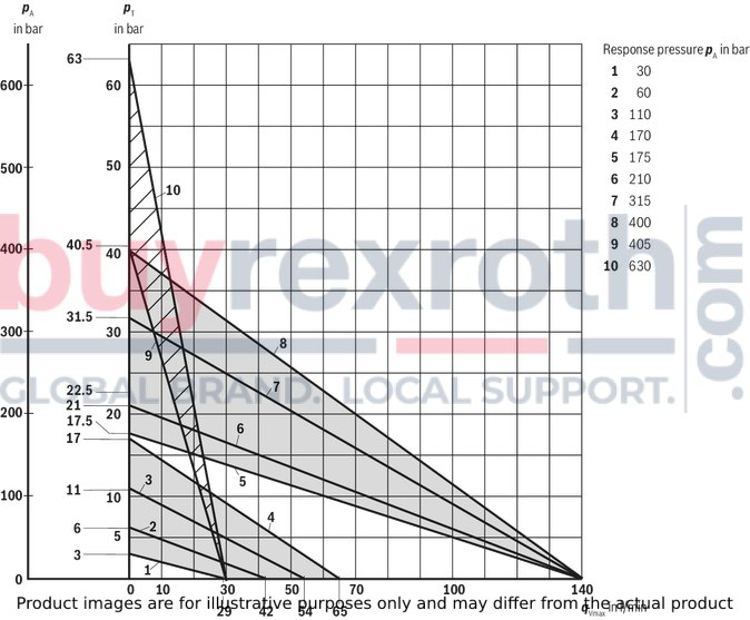
|
Characteristic curves |
Response pressurepA in bar |
|
1 |
30 |
|
2 |
60 |
|
3 |
110 |
|
4 |
170 |
|
5 |
175 |
|
6 |
210 |
|
7 |
315 |
|
8 |
400 |
|
9 |
405 |
|
10 |
630 |
|
Characteristic curves for intermediate values can be generated by interpolation. See "Counter pressure in the discharge line". |
|
pA Response pressure in bar
pT Maximum counter pressure in the discharge line (port T) in bar
qVmax Maximum flow in l/min
Interpolations
Characteristic curves: Counter pressure in the discharge line – size 20
Diagram for determining the maximum admissible counter pressure pT in the discharge line at port T of the valve dependent on the flow qVmax for valves DBDS 20...1X/...E with different response pressures pA.
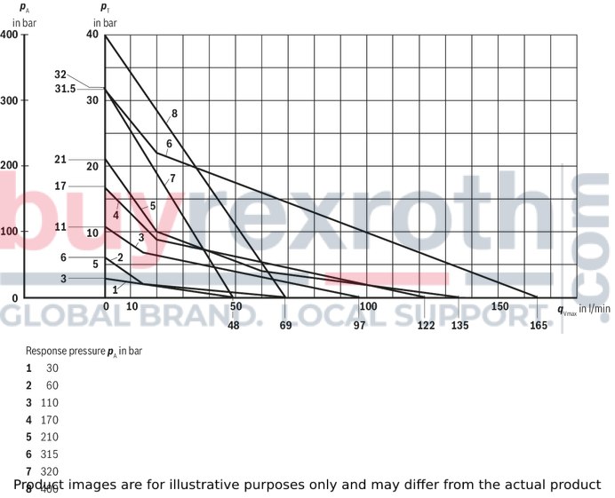
|
Characteristic curves |
Response pressurepA in bar |
|
1 |
30 |
|
2 |
60 |
|
3 |
110 |
|
4 |
170 |
|
5 |
210 |
|
6 |
315 |
|
7 |
320 |
|
8 |
400 |
|
Characteristic curves for intermediate values can be generated by interpolation. See "Counter pressure in the discharge line". |
|
pA response pressure in bar
pT Maximum counter pressure in the discharge line (port T) in bar
qVmax Maximum flow in l/min
Characteristic curves: Counter pressure in the discharge line – size 30
Diagram for determining the maximum counter pressure pT in the discharge line at port T of the valve dependent on the flow qVmax for valves DBDS 30...1X/...E with different response pressures pA.
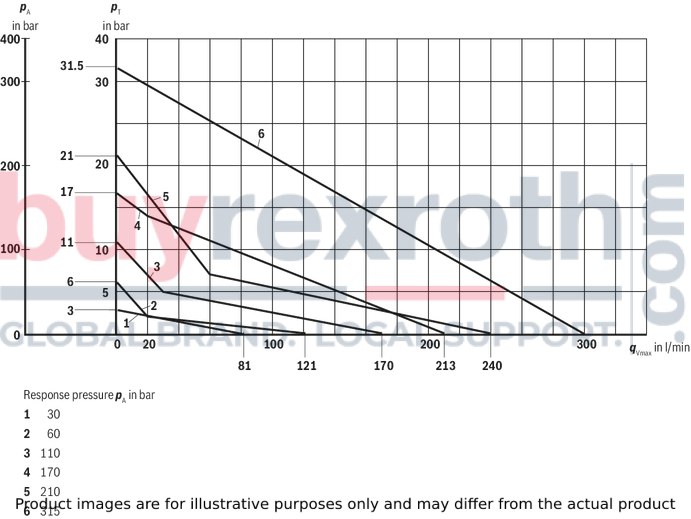
|
Characteristic curves |
Response pressurepA in bar |
|
1 |
30 |
|
2 |
60 |
|
3 |
110 |
|
4 |
170 |
|
5 |
210 |
|
6 |
315 |
|
Characteristic curves for intermediate values can be generated by interpolation. See "Counter pressure in the discharge line". |
|
pA response pressure in bar
pT Maximum counter pressure in the discharge line (port T) in bar
qVmax Maximum flow in l/min
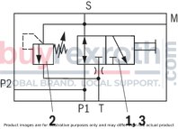
DN08
Version "M" (manual unloading)
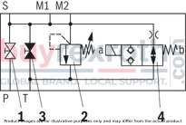
Version "E" (manual and electro-magnetic unloading)
DN10, 20 and 30
Version "M" (manual unloading)
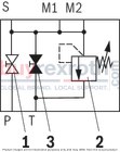
|
1 |
System shut-off cock |
|
2 |
Pressure relief valve |
|
3 |
Manual unloading |
|
4 |
Electro-magnetic unloading, optional |
|
Connection designation |
|
|
M, M1, M2 |
Measuring port |
|
P, P1, P2 |
Pump connection |
|
S |
Accumulator port |
|
T |
Tank port |
Dimensions: Version "08…" (DN08)
Dimensions in mm
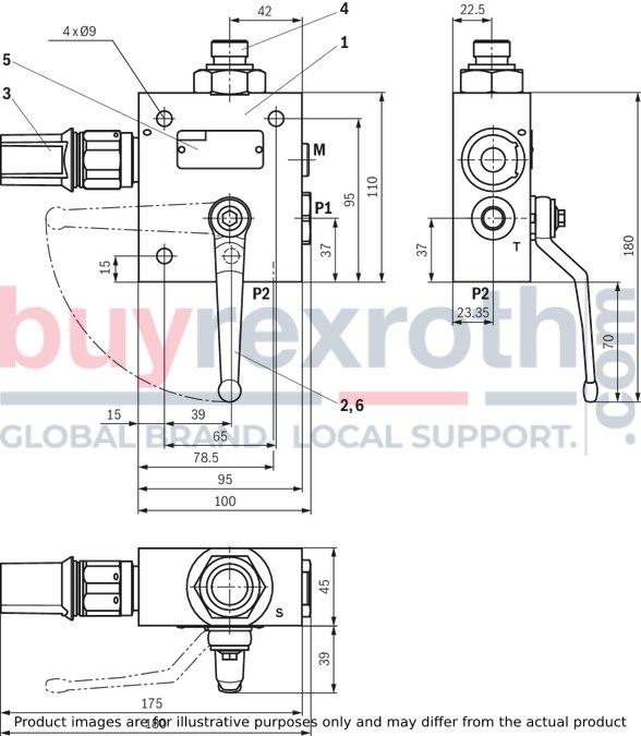
|
Connection thread |
BSP |
|
|
M1; M2 |
Measuring port |
G1/4 |
|
P1 |
Pump connection |
G3/8 |
|
P2 |
Pump connection |
G1/2 |
|
T |
Tank port |
G1/4 |
|
S |
Accumulator port |
M20 x 1.51) |
|
1) Mounting cavity according to DIN EN 9974-1 |
||
Item explanations at the end.
Characteristic curves for type-examination tested safety valves type DBDS see “Diagrams/characteristic curves”.
Dimensions: Version "10…" (DN10)
Dimensions in mm
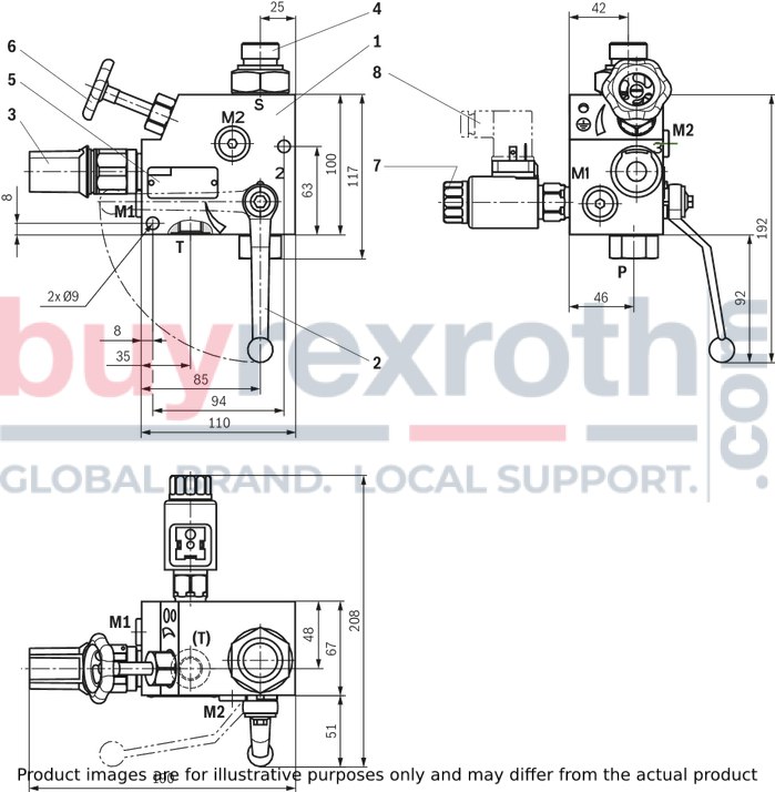
|
Connection thread |
BSP |
SAE |
|
|
M1; M2 |
Measuring port |
G1/4 |
7/6-20 UNF |
|
P |
Pump connection |
G1/2 |
3/4-16 UNF |
|
T |
Tank port |
G3/8 |
9/16-18 UNF |
|
S |
Accumulator port |
M33 x 2 |
M33 x 2 |
Item explanations at the end.
Characteristic curves for type-examination tested safety valves type DBDS see “Diagrams/characteristic curves”.
Dimensions: Version "20…" (DN20)
Dimensions in mm
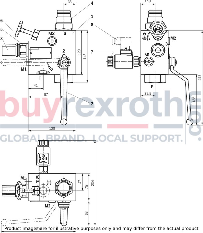
|
Connection thread |
BSP |
SAE |
|
|
M1; M2 |
Measuring port |
G1/4 |
7/6-20 UNF |
|
P |
Pump connection |
G1 |
1 5/16-12 UNF |
|
T |
Tank port |
G1/2 |
3/4-16 UNF |
|
S |
Accumulator port |
M33 x 2 |
M33 x 2 |
Item explanations at the end.
Characteristic curves for type-examination tested safety valves type DBDS see “Diagrams/characteristic curves”.
Dimensions: Version "30…" (DN30)
Dimensions in mm
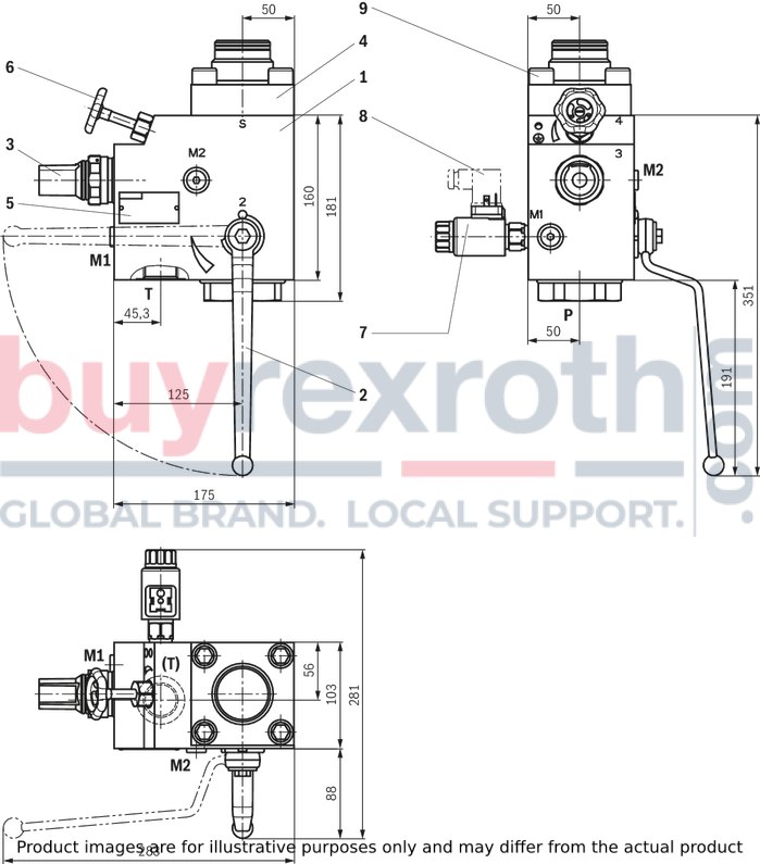
|
Connection thread |
BSP |
SAE |
|
|
M1; M2 |
Measuring port |
G1/4 |
7/6-20 UNF |
|
P |
Pump connection |
G1 1/2 |
1 7/8-12 UNF |
|
T |
Tank port |
G1 |
1 5/16-12 UNF |
|
S |
Accumulator port (flange) |
see "Accessories - Accumulator adapter BSP/SAE" |
|
Item explanations at the end.
Characteristic curves for type-examination tested safety valves type DBDS see “Diagrams/characteristic curves”.
Dimensions: Version "30…SO30" (DN30)
Dimensions in mm
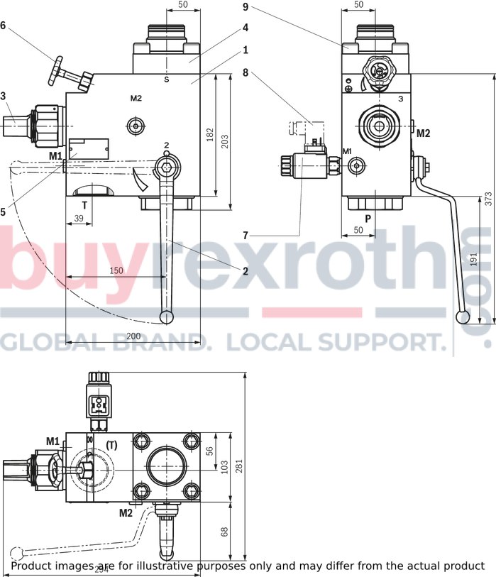
|
Connection thread |
BSP |
SAE |
|
|
M1; M2 |
Measuring port |
G1/4 |
7/6-20 UNF |
|
P |
Pump connection |
G1 1/2 |
1 7/8-12 UNF |
|
T |
Tank port |
G1 1/2 |
1 7/8-12 UNF |
|
S |
Accumulator port (flange) |
see "Accessories - Accumulator adapter BSP/SAE" |
|
Item explanations at the end.
Characteristic curves for type-examination tested safety valves type DBDS see “Diagrams/characteristic curves”.
Dimensions: Version "P30…" subplate mounting (DN30)
Dimensions in mm
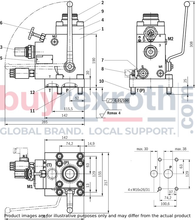
|
Connection thread |
BSP |
SAE |
|
|
M1; M2 |
Measuring port |
G1/4 |
7/6-20 UNF |
|
S |
Accumulator port (flange) |
see "Accessories - Accumulator adapter BSP/SAE" |
|
Item explanations at the end.
Characteristic curves for type-examination tested safety valves type DBDS see “Diagrams/characteristic curves”.
Dimensions: Special versions "SO103" and "SO104" (for NG10 to NG30 only)
"SO103" shut-off device with two shut-off positions (open or closed)
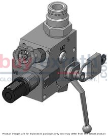
"SO104" shut-off device with one shut-off position (closed)
(padlock not included in the scope of delivery)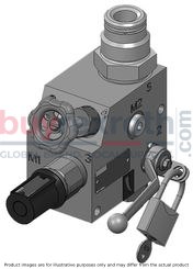
Dimensions: Item explanations
|
1 |
Block |
|
2 |
System shut-off cock |
|
3 |
Pressure relief valve |
|
4 |
Accumulator adapter, see "Accessories" |
|
5 |
Name plate |
|
6 |
Manual unloading |
|
7 |
Electro-magnetic unloading, optional (version "E" only) |
|
8 |
Mating connectors, separate order |
|
9 |
Hexagon socket head cap screws 4 pieces ISO 4762 - M16 x 45 - 10.9 Tightening torque MA = 250+10 Nm |
|
10 |
Hexagon socket head cap screws 4 pieces ISO 4762 - M16 x 55 - 10.9 Tightening torque MA = 250+10 Nm |
|
11 |
R-ring 42.5 x 3 x 3 Shore 90 |
|
12 |
R-ring 34.52 x 3.53 x 3.53 Shore 90 |
Tightening torque: Pressure relief valve DBD
|
Size |
Tightening torques MA for screw-in cartridge valves |
|||
|
Pressure rating up to 200 bar |
Pressure rating up to 400 bar |
|||
|
Nm |
Nm |
Nm 1) |
Nm |
|
| 8 | 50 1) | ± 5 | 80 | ± 5 |
| 10 | 100 1) | ± 5 | 150 | ± 10 |
| 20 | 150 1) | ± 10 | 300 | ± 15 |
| 30 | 350 1) | ± 20 | 500 | ± 30 |
| 1) | The tightening torques are guidelines with a friction coefficient μtotal = 0.12 and when using a manual torque wrench. |
Mating connectors according to DIN EN 175301-803
|
For details and more mating connectors see data sheet 08006 |
|||||
|
Valve side |
Color |
Part number |
|||
|
Without circuitry |
With indicator light |
With rectifier |
With indicator light and Zener diode suppression circuit |
||
|
a |
gray |
R901017010 |
— |
— |
— |
|
b |
black |
R901017011 |
— |
— |
— |
|
a/b |
black |
— |
R901017022 |
R901017025 |
R901017026 |
Accumulator adapter BSP thread, maximum operating pressure 350 bar
|
Fig. 1 
|
Fig. 2 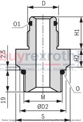
|
Fig. 3 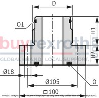
|
|
Nominal diameter version |
Accumulator type |
Accumulator DN |
Accumulator adapter |
Fig. |
D |
ØD1 |
ØD2 |
H1 |
H2 |
M |
O |
O1 |
S |
||||||
|
ABZSS10, ABZSS20 |
ABZSS08 |
ABZSS10, ABZSS20 |
ABZSS08 |
ABZSS10, ABZSS20 |
ABZSS10, ABZSS20 |
ABZSS08 |
ABZSS10, ABZSS20 |
ABZSS08 |
|
|
ABZSS10, ABZSS20 |
ABZSS08 |
|||||||
|
mm |
mm |
mm |
mm |
mm |
mm |
||||||||||||||
|
ABZSS08 ABZSS10 ABZSS20 |
Diaphragm type accumulator data sheet 50150 | 0.075 | S30 | S104 | 1 | G1/2A | 26.9 | 39.9 | 35 | 14 | 19.5 | M33 x 2 | M20 x 1.5 | Profile seal ring G1/2A according to DIN 3869 | 24 x 2 | - | Profile seal ring G1/2A according to DIN 3869 | SW41 | SW36 |
| 0.16 | |||||||||||||||||||
| 0.32 | |||||||||||||||||||
| 0.5 | |||||||||||||||||||
| 0.7 | |||||||||||||||||||
| 1 | |||||||||||||||||||
| 1.4 | |||||||||||||||||||
| 2 | S31 | S108 | G3/4A | 32 | 16 | Profile seal ring G3/4A according to DIN 3869 | Profile seal ring G3/4A according to DIN 3869 | ||||||||||||
| 2.8 | |||||||||||||||||||
| 3.5 | |||||||||||||||||||
| Bladder-type accumulator Data sheet 50171 | 1 | S10 | S105 | 2 | - | 28 | 15.5 | - | 18 x 2.5 | - | |||||||||
| 2.5 | S12 | S107 | G1 1/14A | 37 | 16.5 | 30 x 3 | SW46 | - | |||||||||||
| 4 | |||||||||||||||||||
| 6 | |||||||||||||||||||
| 10 | S13 | S109 | G2A | 43 | 20.5 | 48 x 3 | SW65 | ||||||||||||
| 20 | |||||||||||||||||||
| 35 | |||||||||||||||||||
| 50 | |||||||||||||||||||
|
ABZSS30 ABZSSP30 - |
2.5 | S307 | - | 3 | G1 1/4A | - | - | 37 | 30 | - | - | 56.52 x 5.33 | 30 x 3 | - | |||||
| 4 | |||||||||||||||||||
| 6 | |||||||||||||||||||
| 10 | S309 | G2A | 43 | 48 x 3 | |||||||||||||||
| 20 | |||||||||||||||||||
| 35 | |||||||||||||||||||
| 50 | |||||||||||||||||||
Ordering code accumulator adapter BSP thread
|
Version |
Accumulator adapter |
Part number |
Accumulator adapter |
Part number |
|
FKM |
NBR2) |
|||
|
S10 |
S10V/G3/4-M33X2 *BG |
R900545254 |
S10M/G3/4-M33X2 *BG |
R900862699 |
|
S12 |
S12V/G1 1/4-M33X2 *BG |
R900545255 |
S12M/G1 1/4-M33X2 *BG |
R900862700 |
|
S13 |
S13V/G2-M33X2 *BG |
R900545256 |
S13M/G2-M33X2 *BG |
R900862701 |
|
S30 |
S30V/G1/2-M33X2 *BG |
R900545252 |
S30M/G1/2-M33X2 *BG |
R900862695 |
|
S31 |
S31V/G3/4-M33X2 *BG |
R900545253 |
S31M/G3/4-M33X2 *BG |
R900862697 |
|
S104 |
S104V/G1/2-M20X1,5* & |
R901265402 |
S104M/G1/2-M20X1,5* & |
R901265401 |
|
S105 |
S105V/G3/4-M20X1,5* & |
R901265411 |
S105M/G3/4-M20X1,5* & |
R901265407 |
|
S107 |
S107V/G11/4-M20X1,5*& |
R901265412 |
S107M/G11/4-M20X1,5*& |
R901265422 |
|
S108 |
S108V/G3/4-M20X1,5* & |
R901265434 |
S108M/G3/4-M20X1,5* & |
R901265425 |
|
S109 |
S109V/G2-M20X1,5* & |
R901265408 |
S109M/G2-M20X1,5* & |
R901265404 |
|
S3071) |
S307V/G 11/4-DN32 *BG |
R900085303 |
S307M/G 11/4-DN32 *BG |
R900067050 |
|
S3091) |
S309V/G2-DN32 *BG |
R900545858 |
S309M/G2-DN32 *BG |
R900862702 |
|
1) Scope of delivery includes 4 hexagon socket head cap screws ISO 4762 - M16 x 45 - 10.9 |
||||
|
2) Special version |
||||
Accumulator adapter SAE thread, maximum operating pressure 350 bar
|
Fig. 1 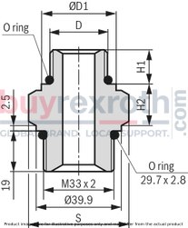
|
Fig. 2 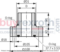
|
|
Nominal diameter version |
Accumulator type |
Accumulator DN |
Accumulator adapter |
Fig. |
D |
ØD1 |
H1 |
H2 |
O-ring |
S |
|
mm |
mm |
mm |
mm |
|||||||
|
ABZSS10 ABZSS20 - |
Diaphragm type accumulator data sheet 50150 | 0.075 | S64 | 1 | 3/4-16 UNF-2A | 23 | 11.4 | 18.1 | 16.36 x 2.21 | SW41 |
| 0.16 | ||||||||||
| 0.32 | ||||||||||
| 0.5 | ||||||||||
| 0.7 | ||||||||||
| 1 | ||||||||||
| 1.4 | ||||||||||
| 2 | S60 | 1 1/16-12 UN-2A | 32 | 15.2 | 18.3 | 23 x 3 | ||||
| 2.8 | ||||||||||
| 3.5 | ||||||||||
| Bladder-type accumulator Data sheet 50171 | 1 | |||||||||
| 2.5 | S62 | 1 5/8-12 UN-2A | 48 | 20.3 | 38 x 3 | SW65 | ||||
| 4 | ||||||||||
| 6 | ||||||||||
| 10 | S63 | 1 7/8-12 UN-2A | 54 | 44 x 3 | ||||||
| 20 | ||||||||||
| 35 | ||||||||||
| 50 | ||||||||||
|
ABZSS30 - - |
1 | S620 | 2 | 1 5/8-12 UN-2A | 48 | 33.8 | 38 x 3 | - | ||
| 4 | ||||||||||
| 6 | ||||||||||
| 10 | S630 | 1 7/8-12 UN-2A | 54 | 44 x 3 | ||||||
| 20 | ||||||||||
| 35 | ||||||||||
| 50 |
Ordering code accumulator adapter SAE thread
|
Version |
Accumulator adapter |
Part number |
Accumulator adapter |
Part number |
|
FKM |
NBR2) |
|||
|
S60 |
S60V/ 1 1/16-12UN-M33x2 |
R900618788 |
S60M/ 1 1/16-12UN-M33x2 |
R900618799 |
|
S62 |
S62V/ 1 5/8-12UN-M33x2 |
R900618800 |
S62M/ 1 5/8-12UN-M33x2 |
R900618801 |
|
S63 |
S63V/ 1 7/8-12UN-M33x2 |
R900618803 |
S63M/ 1 7/8-12UN-M33x2 |
R900618804 |
|
S64 |
S64V/ 3/4-16UNF-M33x2 |
R900618805 |
S64M/ 3/4-16UNF-M33x2 |
R900618806 |
|
S6201) |
S620V/ 1 5/8-12UN-DN32 |
R900618813 |
S620M/ 1 5/8-12UN-DN32 |
R900618814 |
|
S6301) |
S630V/ 1 7/8-12UN-DN32 |
R900618817 |
S630M/ 1 7/8-12UN-DN32 |
R900618815 |
|
1) Scope of delivery includes 4 hexagon socket head cap screws ISO 4762 - M16 x 45 - 10.9 |
||||
|
2) Special version |
||||
Safety instructions: Type-examination tested safety valves type DBDS 1)
Before ordering a type-examination tested safety valve, it must be observed that for the desired response pressure p, the maximum admissible flow qVmax of the safety valve must be larger than the maximum possible flow of the system/accumulator to be secured. According to the Pressure Equipment Directive 2014/68/EU, the increase in the system pressure due to the flow must not exceed 10 % of the set response pressure (see component marking). The maximum admissible flow qVmax stated in the component marking must not be exceeded. Discharge lines of safety valves must end in a risk-free manner. Fluid must not accumulate in the discharge system (see data sheet AD2000 A2).
Always observe application notes!
In the plant, the response pressure specified in the component marking is set at a flow of 2 l/min. The maximum flow stated in the component marking applies for applications without counter pressure in the discharge line (port T). By removing the lead seal at the safety valve, the approval according to the Pressure Equipment Directive becomes void! Basically, the requirements of the Pressure Equipment Directive and of data sheet AD 2000 A2 have to be observed! It is recommended to secure type-examination tested safety valves against inadmissible disassembly by means of wiring and sealing with the housing/block (bore available in the adjustment type).
Notice:
The system pressure increases by the counter pressure in the discharge line (port T) due to the increasing flow. (Observe the data sheet AD 2000 A 2, point 6.3!) To ensure that this increase in system pressure caused by the flow does not exceed the value of 10 % of the set response pressure, the admissible flow has to be reduced dependent on the counter pressure in the discharge line (port T) (see diagrams/characteristic curves).
1) Component series 1X, according to the Pressure Equipment Directive 2014/68/EU
Related Products
R901091294
$4,212.00 USD
R901500181
$4,222.00 USD
R900077650
$54.50 USD
R901344986
$2,263.00 USD
R901443534
$3,923.00 USD


