PRESSURE REDUCING VALVE DREE20-6X/200YG24K31F1V
Manufacturer: Bosch Rexroth
Material #: R901272515
Model : DREE20-6X/200YG24K31F1V
***Disclaimer: The following summary contains information gathered from various sources such as product descriptions, technical specifications and catalogs. While efforts have been made to provide accurate details, inaccuracies may occur. It is advised to verify all information by contacting Bosch Rexroth directly.***
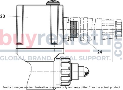
The Bosch Rexroth DREE20-6X/200YG24K31F1V (R901272515) is a high-performance industrial hydraulic valve designed for reliable pressure reduction in accordance with the command value signal. This valve features a size B, with an electrical connection description of Connector pole PE conforming to DIN EN standards. It is capable of subplate mounting and conforms to CE according to the EMC Directive EU.
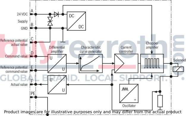
The DREE20-6X/200YG24K31F1V is equipped with integrated electronics for actuation and has a maximum pressure capacity, with a supply voltage of 24 VDC. The valve has multiple ports and offers a maximum flow rate. Its construction includes FKM seals and it can handle various hydraulic fluids such as HL, HLP, HLPD, HVLP, HVLPD, HETG, HEES, HEPG, HFDU, and HFDR.
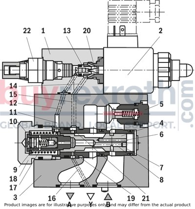
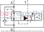
This model operates by utilizing a proportional solenoid that sets the pressure in channel A command-value dependently. In its default state without pressure in channel B, the spring holds the main spool in its initial position ensuring that there is no startup jump by keeping the connection from channel B to A closed.
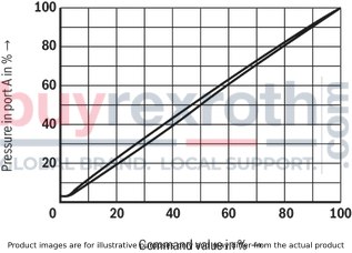
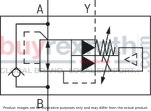
The design also includes an optional check valve between channels A and B for free flowback and an optional maximum pressure limitation feature for additional safety against excessive electric control current at the proportional solenoid. The DREE20-6X/200YG24K31F1V valve boasts a linearized pressure-command value characteristic curve and good transient response characteristics making it suitable for various demanding applications requiring precise pressure control.
$4,220.00 USD
More are expected on September 1, 2026
Note: Sales tax, shipping, and applicable tariffs will be calculated at checkout.| Qty | Price | Savings |
|---|---|---|
| 5-24 | $4,114.50 USD | $105.50 USD |
| 25+ | $4,009.00 USD | $211.00 USD |
Status: This product is temporarily out of stock.
Qty: Delivered as early as September 1, 2026 when ordered in


