***Disclaimer: The following summary contains information gathered from various sources such as product descriptions, technical specifications and catalogs. While efforts have been made to provide accurate details, inaccuracies may occur. It is advised to verify all information by contacting Bosch Rexroth directly.***
The Bosch Rexroth Z4WE6E63-3X/EG24N9K4=CSA (R900976091) is a high-performance direct-controlled directional slide valve featuring solenoid actuation and designed for sandwich plate mounting. This valve is versatile in its applications, serving as a stop, straight-through, or stop straight-through short circuit valve. It adheres to the DIN form A porting pattern standards without a locating hole, while also meeting the ISO pattern with a locating hole for diverse integration requirements.
The Z4WE6E63-3X/EG24N9K4=CSA is engineered for robust performance with a maximum operating pressure of up to 350 bar and can accommodate maximum flow rates of up to 80 l/min, ensuring efficient fluid control in hydraulic systems. The wet-pin AC or DC solenoids provide reliable actuation of the valve, while the optional manual override feature adds an extra layer of operational security and convenience for maintenance or emergency situations.
This model's design facilitates ease of installation and maintenance due to its standardized porting patterns and compact sandwich plate configuration. The valve's capabilities make it suitable for use in various hydraulic applications that require precise control of fluid direction and flow rate. Bosch Rexroth's commitment to quality ensures that this directional slide valve delivers consistent performance and durability in demanding operational environments.
$736.00 USD
More are expected on September 2, 2026
Status: This product is temporarily out of stock.
Qty: Delivered as early as September 2, 2026 when ordered in
This product is eligible for factory repair.
Direct-controlled directional slide valve with solenoid actuation Sandwich plate valve As stop straight-through valve or stop straight-through short circuit valve Porting pattern according to DIN 24340 form A (without locating hole), (standard) Porting pattern according to ISO 4401-03-02-0-05 (with locating hole) Wet-pin AC or DC solenoids Manual override, optional
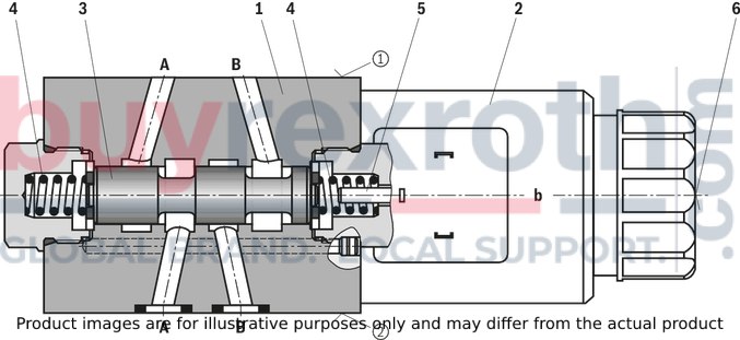
Type Z4WE 6…
|
➀ |
component side |
|
➁ |
plate side |
|
01 |
02 |
03 |
05 |
07 |
08 |
09 |
10 |
11 |
12 |
13 |
14 |
||
|
Z4WE |
6 |
‒ |
3X |
/ |
E |
K4 |
* |
|
01 |
Shut-off valve, sandwich plate |
ZW4E |
|
02 |
Size |
6 |
|
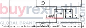
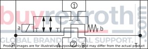
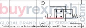
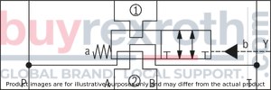
Symbols |
||
|
03 |
e.g. D24, E51, E53, ...; with DC or AC solenoids e.g. X250, X252, ...; only with DC solenoids (AC voltage on request) |
|
|
05 |
Component series 30 ... 39 (30 ... 39: unchanged installation and connection dimensions) |
3X |
|
07 |
High-power solenoid, wet-pin, with detachable coil |
E |
|
08 |
Direct voltage 24 V |
G24 |
|
Alternating voltage 230 V, 50/60 Hz |
W230 |
|
|
Direct voltage 205 V |
G2051) |
|
|
09 |
With concealed manual override (standard) |
N9 |
|
With manual override |
N |
|
|
Without manual override |
no code |
|
|
Electrical connection |
||
|
10 |
Without mating connector, with connector DIN EN 175301-803 |
K42) |
|
Spool position monitoring |
||
|
11 |
Without position switch |
no code |
|
Monitored spool position "a" |
QMAG24 |
|
|
Monitored spool position "b" |
QMBG24 |
|
|
Monitored rest position |
QM0G24 |
|
|
Seal material |
||
|
12 |
NBR seals |
no code |
|
FKM seals (other seals upon request) |
V |
|
|
Observe compatibility of seals with hydraulic fluid used. |
||
|
13 |
no code |
|
|
With locating hole |
/603) |
|
|
With locating hole and locking pin ISO 8752-3x8-St |
/62 |
|
|
14 |
Further details in the plain text |
* |
Notice!
Inductive position switch type QM not available for symbol "E53“
|
AC voltage mains (admissible voltage tolerance ± 10%) |
Nominal voltage of the DC solenoid in case of operation with alternating voltage |
Ordering code |
|
110 V - 50/60 Hz |
96 V |
G96 |
|
230 V - 50/60 Hz |
205 V |
G205 |
Preferred types and standard units are contained in the EPS (standard price list).
general
|
Size |
6 | ||
|
Weight |
Valve with one solenoid |
kg |
1.2 |
|
Valve with two solenoids |
kg |
1.6 | |
|
Installation position |
any | ||
|
Ambient temperature ranges (NBR seals) |
°C |
-30 … +50 | |
|
Ambient temperature ranges (FKM seals) |
°C |
-20 … +70 | |
|
MTTFD values according to EN ISO 13849 1) |
Years |
150 | |
|
Admissible shock and vibration loads |
see data sheet 08012 | ||
| 1) | For further details, see data sheet 08012 |
hydraulic
|
Size |
6 | |||
|
Maximum operating pressure |
Port P |
bar |
315 | |
|
Anschluss A |
bar |
315 | ||
|
Port B |
bar |
315 | ||
|
Port T |
with DC solenoid |
bar |
210 | |
|
with AC solenoid |
bar |
160 | ||
|
Maximum flow |
l/min |
50 | ||
|
Hydraulic fluid |
see table | |||
|
Hydraulic fluid temperature range (NBR seals) |
°C |
-30 … +80 | ||
|
Hydraulic fluid temperature range (FKM seals) |
°C |
-20 … +80 | ||
|
Viscosity range |
mm²/s |
2.8 … 500 | ||
|
Maximum admissible degree of contamination of the hydraulic fluid 1) |
Class 20/18/15 according to ISO 4406 (c) | |||
| 1) | The cleanliness classes specified for the components must be adhered to in hydraulic systems. Effective filtration prevents faults and simultaneously increases the life cycle of the components. For the selection of the filters, see www.boschrexroth.com/filter. |
electrical
|
Voltage type |
Direct voltage | AC voltage 50/60 Hz | ||
|
Available voltages 1) |
V |
12 / 24 / 96 / 205 | 110 / 230 | |
|
Voltage tolerance |
Nominal voltage |
% |
± 10 | ± 10 |
|
Power consumption |
W |
30 | - | |
|
Holding power |
VA |
- | 50 | |
|
Switch-on power |
VA |
- | 220 | |
|
Duty cycle |
% |
100 | 100 | |
|
Switching time according to ISO 6403 2) |
On |
ms |
20 … 45 | 10 … 20 |
|
Off |
ms |
10 … 25 | 15 … 40 | |
|
Maximum switching frequency |
1/h |
15000 | 7200 | |
|
Maximum coil temperature 3) |
°C |
150 | 180 | |
|
Protection class according to DIN EN 60529 |
IP65 (with mating connector mounted and locked) | |||
| 1) | Special voltages available upon request |
| 2) | The switching times were determined at a hydraulic fluid temperature of 40 °C and a viscosity of 46 mm2/s. Deviating hydraulic fluid temperatures can result in different switching times. Switching times change dependent on operating time and application conditions. |
| 3) | Due to the surface temperatures of the solenoid coils, the standards ISO 13732-1 and EN 982 need to be adhered to!The specified surface temperature in AC solenoids is valid for fault-free operation. In the error case (e. g. blocking of the control spool), the surface temperature may increase above 180 °C [356 °F]. Thus, the system must be checked for possible dangers considering the flash point (see table Hydraulic fluids).As fuse protection, circuit breakers (see table Circuit breakers) must be used, unless the creation of an ignitable atmosphere can be excluded in a different way. Thus, the surface temperature can – in the error case – be limited to maximally 220 °C [428 °F].Within a time interval of 0.6 s, the tripping current must be 8 to 10 times the nominal power supply (tripping characteristics “K”).The required non-tripping current of the fuse must not fall below the value I1 (see table Circuit breakers with tripping characteristics “K”). The maximum tripping current of the fuse must not exceed the value I2 (see table Circuit breakers with tripping characteristics “K”).The temperature dependence of the tripping behavior of the circuit breakers has to be observed according to the manufacturer's specifications. |
Notices!
Actuation of the manual override is only possible up to a tank pressure of approx. 50 bar. Avoid damage to the bore of the manual override! (Special tool for the operation, separate order, material no. R900024943). When the manual override is blocked, the actuation of the solenoid must be prevented! The simultaneous actuation of the solenoids must be prevented!
Notice!
AC solenoids can be used for 2 or 3 mains; e.g. solenoid type W110 for: 110 V, 50 Hz; 110 V, 60 Hz; 120 V, 60 Hz
Circuit breakers with tripping characteristics K according to EN 60898-1 (VDE 0641-11), EN 60947-2 (VDE 0660-101), IEC 60898 and IEC 60947-2
|
Valve nominal voltage |
Nominal power supply |
Recommended fuse rated current |
|
|
50 Hz |
60 Hz |
||
|
24 |
2 |
1,5 |
3 |
|
42
|
1,26 |
0,98 |
2 |
|
48 |
1 |
0,95 |
1,6 |
|
100 |
0,56 |
0,5 |
1 |
|
110 |
0,52 |
0,45 |
0,75 |
|
115
|
0,45 |
0,37 |
0,75 |
|
127 |
0,42 |
0,32 |
0,75 |
|
200 |
0,29 |
0,26 |
0,5 |
|
220 |
0,27
|
0,23 |
0,5 |
|
230 |
0,23 |
0,17 |
0,5 |
|
240 |
0,23 |
0,19 |
0,5 |
When establishing the electrical connection, the protective earthing conductor (PE ⊥) must be connected correctly.
Inductive position switch type QM: electrical connection
The electric connection is realized via a 4-pole mating connector (separate order) with connection thread M12 x 1.
electrical
|
Connection voltage (DC voltage) |
V |
24 | ||
|
Voltage tolerance (connection voltage) |
+30 %/-15 % | |||
|
Admissible residual ripple |
% |
≤ 10 | ||
|
Max. load capacity |
mA |
400 | ||
|
Switching outputs 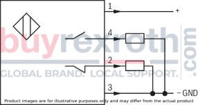
|
PNP transistor outputs, load between switching outputs and GND | |||
|
Pinout 
|
1 |
V |
24 | |
|
2, 4 |
Switching output |
mA |
400 | |
|
3 |
Earthing (GND) |
V |
0 | |
For applications outside these parameters, please consult us!
|
Ordering code |
Mains |
|
W110 |
110 V, 50 Hz |
|
110 V, 60 Hz |
|
|
120 V, 60 Hz |
|
|
W 230 |
230 V, 50 Hz |
|
230 V, 60 Hz |
|
Hydraulic fluid |
Classification |
Suitable sealing materials |
Standards |
|
|
Mineral oils and related hydrocarbons |
HL, HLP, HLPD, HVLP, HVLPD |
NBR, FKM |
DIN 51524 |
|
|
Environmentally compatible |
Insoluble in water |
HETG |
NBR, FKM |
ISO 15380 |
|
HEES |
FKM |
|||
|
Soluble in water |
HEPG |
FKM |
ISO 15380 |
|
|
Containing water |
HFC |
NBR |
ISO 12922 |
|
(measured with HLP46, ϑOil = 40 ±5 °C)
Δp-qV characteristic curves
Spool symbols D27, E46, E54, E56, E57, E62, E115, E127, E129, E130, E131, E132, ,E135, E136, E138, E139, E140, E141, E144, E145, E145A, E146, E147, E166, E181 and E183 on request.

|
Symbol |
A➁‒A➀ |
A➀‒A➁ |
B➁‒B➀ |
B➀‒B➁ |
A➁‒B➁ |
B➁‒A➁ |
T➁‒T➀ |
P➁‒P➀ |
|
D24 |
4 |
1 |
2 |
4 |
3 |
2 |
7 |
7 |
|
E51 |
3 |
1 |
1 |
3 |
‒ |
‒ |
7 |
7 |
|
E53 |
2 |
2 |
2 |
2 |
5 |
2 |
7 |
7 |
|
E63 |
2 |
5 |
5 |
3 |
‒ |
‒ |
7 |
7 |
|
E68 |
4 |
4 |
6 |
5 |
4 |
5 |
7 |
7 |
|
E137 |
1 |
4 |
3 |
2 |
5 |
6 |
7 |
7 |
Δp-qV characteristic curves
Spool symbols X161, X163, X181, X183, X187, X188, X193 and X157 on request.

|
Symbol |
Spool position |
A➀‒A➁ A➁‒A➀ |
B➀‒B➁ |
B➁‒B➀ |
T➁‒T➀ |
P➁‒P➀ |
P➀‒T➁ |
B➁‒T➁ |
P➁‒P➀ |
A➁‒T➁ |
P➁‒A➁ B➁‒T➁ |
|
X250 |
16 |
17 |
17 |
18 |
13 |
10 |
‒ |
‒ |
‒ |
‒ |
|
|
X252 |
16 |
17 |
17 |
18 |
9 |
11 |
‒ |
‒ |
‒ |
‒ |
|
|
X253 |
13 |
14 |
14 |
19 |
18 |
‒ |
‒ |
‒ |
8 |
‒ |
|
|
X254 |
16 |
12 |
13 |
18 |
18 |
‒ |
12 |
‒ |
‒ |
‒ |
|
|
X255 |
0 |
‒ |
‒ |
‒ |
15 |
‒ |
‒ |
8 |
‒ |
8 |
‒ |
|
a |
12 |
‒ |
‒ |
‒ |
‒ |
‒ |
13 |
‒ |
‒ |
‒ |
|
|
b |
‒ |
12 |
12 |
‒ |
‒ |
‒ |
‒ |
‒ |
13 |
‒ |
|
|
X256 |
12 |
9 |
9 |
18 |
‒ |
‒ |
‒ |
18 |
‒ |
20 |
Performance limits(measured with HLP46, ϑOil = 40 ±5 °C and 24 V DC voltage)
Spool symbols D27, E46, E54, E56, E57, E62, E115, E127, E129, E130, E131, E132, E133, E134, E135, E136, E138, E139, E140, E141, E144, E145, E145A, E146, E147, E166, E181, E183, X161, X163, X181, X183, X187, X188, X193 and X157 on request.

Performance limits(measured with HLP46, ϑOil = 40 ±5 °C [104 ±9 °F] and 230 V AC voltage)
Spool symbols D27, E46, E54, E56, E57, E62, E115, E127, E129, E130, E131, E132, ,E135, E136, E138, E139, E140, E141, E144, E145, E145A, E146, E147, E166, E181 and E183 on request.

|
Symbol |
W230–50Hz |
W230–60Hz |
|
E63 |
13 |
16 |
|
E68 |
14 |
18 |
|
E53 |
15 |
18 |
|
E137 |
17 |
17 |
|
E51 |
17 |
17 |
|
D24 |
17 |
17 |
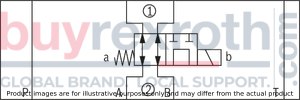
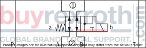
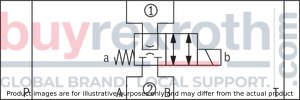
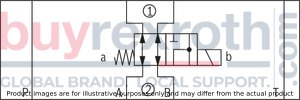
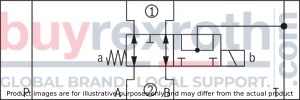
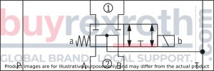
DC or AC voltage
D24
E57
D27

E62
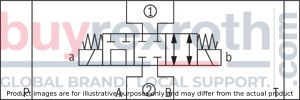
E46
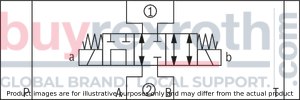
E63
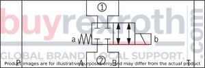
E51
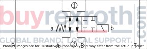
E68
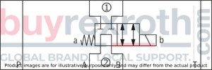
E53
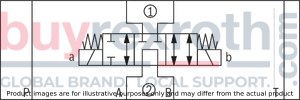
E115
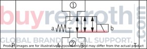
E54

E127
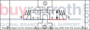
E56
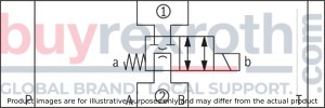
E129
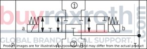
E130
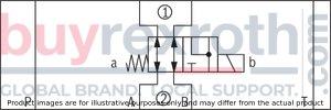
E138

E131
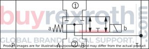
E139
E132
E140

E1351)

| 1) | Throttle installation available on request |
E141
E136

E144
E137
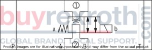
E145
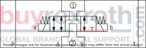
E145A

E166
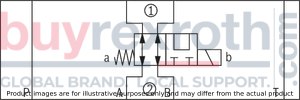
E146
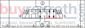
E181
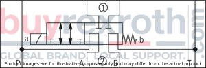
E147
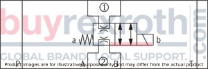
E183
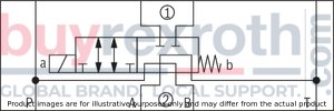
|
➀ |
component side |
|
➁ |
plate side |
Direct voltage
X161
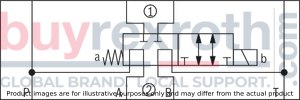
X250
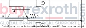
X163
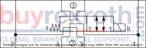
X252
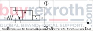
X181
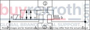
X253
X183
X254
X187
X255
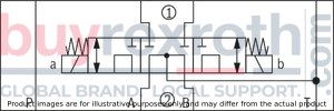
X188
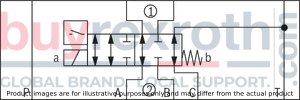
X256
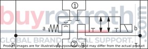
X193
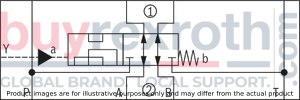
X257

|
➀ |
component side |
|
➁ |
plate side |
Inductive position switch type QM Switching logics
Version QMA
(Position switch on side B, monitored spool position "a")
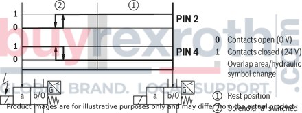
Version QMA
(Position switch on side A, monitored spool position "a")
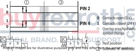
Version QMB
(Position switch on side B, monitored spool position "b")
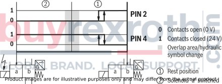
Version QMB
(Position switch on side A, monitored spool position "b")
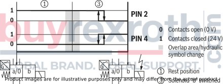
Version QM0
(Position switch on side B, monitored rest position)
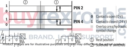
Version QM0
(Position switch on side A, monitored rest position)
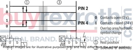
with DC solenoid
Spool symbols D24, E51, E53, E63, E68, E137, …
Dimensions in mm

Spool symbols X250, X252, X253, X254, X255, X256, …
Dimensions in mm

|
Symbol |
Solenoid side |
L1 |
L2 |
L3 |
L4 |
L5 |
L6 |
L7 |
|
mm |
mm |
mm |
mm |
mm |
mm |
mm |
||
| X250 | a | 24.9 | 54.9 | - | 63.3 | 93.3 | - | - |
| X252 | b | 24.9 | 54.9 | 33.5 | - | - | 123.1 | - |
| X253 | b | 18.3 | 54.3 | 26.9 | - | - | 129.7 | - |
| X254 | a | 18.3 | 54.3 | - | 69.9 | 86.7 | - | - |
| X255 | a + b | 25.9 | 53.9 | - | - | 94.3 | 131.1 | 225.4 |
| X256 | b | 12 | 54.8 | 20.6 | - | - | 136 | - |
Spool symbols X161, X163, X181, X183, X187, X188, X193 and X157 on request.
with AC solenoid
Dimensions in mm
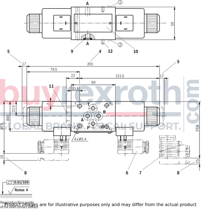
|
➀ |
component side – porting pattern according to ISO 4401-03-02-0-05 (with or without locating hole); (with locating hole Ø3 x 5 mm deep) |
|
➁ |
plate side – porting pattern according to ISO 4401-03-02-0-05 (with locating hole for locking pin ISO 8752-3x8-St; version "/60" and "/62") |
|
3 |
Dimension for valve without manual override |
|
4 |
Dimension for solenoid with concealed manual override "N9" (standard) |
|
5 |
Dimension for valve with manual override "N" |
|
6 |
Mating connector without circuitry (separate order, see data sheet 08006) |
|
7 |
Mating connector with circuitry (separate order, see page data separate order, see data sheet 08006) |
|
8 |
Space required to remove the mating connector |
|
9 |
Identical seal rings for ports A, B, P, T (plate side) |
|
10 |
Name plate |
|
11 |
Plug screw for valve with one solenoid |
|
12 |
Locking pin ISO 8752-3x8-St (only version "/62") |
Subplates according to data sheet 45052
(separate order)
(without locating hole)
G 341/01 (G1/4)
G 342/01 (G3/8)
G 502/01 (G1/2)
(with locating hole)
G 341/60 (G1/4)
G 342/60 (G3/8)
G 502/60 (G1/2)
Valve mounting screws (separate order)
– 4 hexagon socket head cap screws ISO 4762 - M5 - 10.9-flZn-240h-L
with friction coefficient µtotal = 0.09 to 0.14,
tightening torque MA = 7 Nm ±10 %
or
– 4 hexagon socket head cap screws ISO 4762 - M5 - 10.9
with friction coefficient µtotal = 0.12 to 0.17,
tightening torque MA = 8.1 Nm ±10 %
Notice!
Length and tightening torque of the valve mounting screws must be calculated according to the components mounted under and over the sandwich plate valve.
Spool position monitoring
Inductive position switch type QM
Dimensions in mm
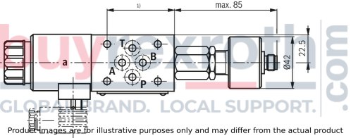
| 1) | For dimensions, see valve dimensions |
Dimensions in mm
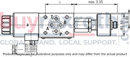
Notice:
The dimensions are nominal dimensions which are subject to tolerances.
Mating connectors for valves with connector “K4”, without circuitry, standard
3P Z4
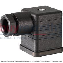
Mating connectors for valves with connector “K4”, without circuitry, standard
3P Z4
For valves with connector “K4” according to EN 175301-803 and ISO 4400, 2-pole + PE, “large cubic connector” Mating connectors for valves with one or two solenoids (individual connection)Data sheet
Spare parts & repair
Mating connectors for valves with connector “K4”, with indicator light
3P Z5L
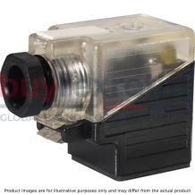
Mating connectors for valves with connector “K4”, with indicator light
3P Z5L
For valves with connector “K4” according to EN 175301-803 and ISO 4400, 2-pole + PE, “large cubic connector” Mating connectors for valves with one or two solenoids (individual connection)Data sheet
Spare parts & repair
Mating connectors for valves with connector “K4”, with indicator light and Zener diode suppression circuit
3P Z5L1

Mating connectors for valves with connector “K4”, with indicator light and Zener diode suppression circuit
3P Z5L1
For valves with connector “K4” according to EN 175301-803 and ISO 4400, 2-pole + PE, “large cubic connector” Mating connectors for valves with one or two solenoids (individual connection)Data sheet
Spare parts & repair
Mating connectors for valves with connector “K4”, with rectifier
3P RZ5

Mating connectors for valves with connector “K4”, with rectifier
3P RZ5
For valves with connector “K4” according to EN 175301-803 and ISO 4400, 2-pole + PE, “large cubic connector” Mating connectors for valves with one or two solenoids (individual connection)Data sheet
Spare parts & repair
Related Products
R900705791
$984.00 USD
R900328799
$1,223.00 USD
R978896877
$660.00 USD
R901421106
$2,732.00 USD
R900401234
$893.00 USD


