


TOOTHED RING PUMP PGZ4-1X/080RA07VE4
Manufacturer: Bosch Rexroth
Material #: R901230040
Model : PGZ4-1X/080RA07VE4
***Disclaimer: The following summary contains information gathered from various sources such as product descriptions, technical specifications and catalogs. While efforts have been made to provide accurate details, inaccuracies may occur. It is advised to verify all information by contacting Bosch Rexroth directly.***
The Bosch Rexroth PGZ4-1X/080RA07VE4 (R901230040) is a high-quality gerotor pump designed for industrial applications that require reliable performance in open circuit systems. This pump is optimized for cooling, filtration, and lubrication circuits, offering a consistent displacement that ensures steady operation across a wide range of viscosities and speeds. Its aluminum housing contributes to its durability while maintaining a lightweight profile.
The PGZ4-1X/080RA07VE4 pump features FKM seals, suitable for various types of hydraulic fluids including HLP, HLPD, HVLP, and HVLPD. It has been engineered to operate with low noise levels and minimal pulsation, enhancing the overall efficiency and comfort during operation. The pump's maximum pressure capability stands at bar while it supports a size of cm³. It operates within a minimum speed of min⁻¹ and can reach up to a maximum speed of max⁻¹.
The unit's maximum flow is l/min which is facilitated by its constant displacement design. The direction of rotation is clockwise, ensuring compatibility with various system designs. Notably absent from this model is the through-drive option, which streamlines its design for specific applications where additional pump mounting is not required.
For ease of installation, this model comes with hole mounting flange according to ISO and VDMA standards. Its robust construction includes an aluminum flange housing; steel components such as the shaft, inner rotor, gerotor; and a cast iron cover—all chosen for their longevity and performance under demanding conditions.
This Bosch Rexroth gerotor pump exemplifies precision engineering for low-pressure applications where dependable fluid transfer is essential—ideal for use in machines such as plastics processing equipment, machine tools, presses, wind turbines, and other mobile or industrial platforms requiring efficient cooling or lubrication systems.
$2,903.39 USD
Availability: Backordered
Ships from US Note: Sales tax, shipping, and applicable tariffs will be calculated at checkout.
Qty:
Delivered as early as February 17, 2027
$3,048.56 USD
Availability: Backordered
Ships from CA Note: Sales tax, shipping, and applicable tariffs will be calculated at checkout.
Qty:
Delivered as early as February 17, 2027
This product is eligible for factory repair.
Gerotor pump, size 80 cm³, pressure 15 bar for cooling or filter circuits
For cooling, filtration and lubrication circuits. Suitable for a broad viscosity and speed range. Low noise and low pulsation level.
Unpacked Weight: 7.891 kg
Low-pressure pump with fixed displacement Very low operating noise Suitable for broad viscosity and speed ranges Excellent suction characteristics Can be combined with axial piston pumps, internal gear pumps and vane pumps Use for: Cooling, filter or lubricant circuits with low pressures in industrial or mobile applications, e.g. plastics processing machines, machine tools, presses and wind turbines.
Set-up
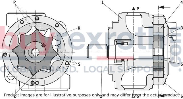
Hydraulic pumps of type PGZ type are gerotor pumps with constant displacement.
They basically comprise of: Flange housing (1), shaft (2), the displacer element inner rotor (3) and gerotor (4) as well as driving disk (5) and cover (6).
Suction and displacement procedure
Via the driving disk, the shaft drives the inner rotor in the indicated direction of rotation. The inner rotor cogs with the gerotor to turn it.
The tooth clearances opening in the suction range (S) suck in the hydraulic fluid. The separation of suction and pressure range is implemented on the opposite side of the meshing area (Z) by means of a radial gap (R) created by the
tooth profile of the gerotor and the inner rotor sliding against each other.
Within the pressure range (P), the hydraulic fluid is pumped into the pressure port by means of the chambers becoming smaller.
Properties
The toothing with cycloid contour has a large meshing length. Filling and displacement areas cover a large angle of rotation. This allows for little flow pulsation and thus very low operating noise.
The shaft and the displacer are supported by a slide bearing and work in a wear-free manner when they are used as intended.
Gerotor pumps PGZ are self-priming.
Materials used
Flange housing (1): aluminum Shaft (2), inner rotor (3), gerotor (4) and driving disk (5): steel Cover (6): Cast iron
Hydraulic pumps of type PGZ type are gerotor pumps with constant displacement. Via a driving disk, the shaft drives the inner rotor in the indicated direction of rotation. The inner rotor cogs with the gerotor to turn it. The tooth clearances opening in the suction range suck in the hydraulic fluid. The separation of suction and pressure range is implemented on the opposite side of the meshing area by means of a radial gap created by the tooth profile of the outer and the inner rotor sliding against each other. Within the pressure range, the hydraulic fluid is pumped into the pressure port by means of the chambers becoming smaller.

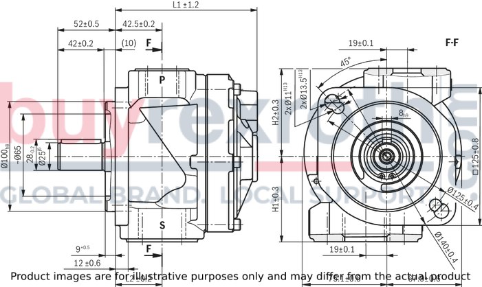
Frame sizes 4 and 5, type...VE4
PGZ 4-1X/ … RA07VE4
PGZ 5-1X/ … RA07VE4
Drive shaft cylindrical,
4-hole mounting flange according to ISO 3019-2 and VDMA 24560
Dimensions in mm
|
Type |
NG |
Part number |
L1 |
L2 |
H1 |
H2 |
S1) |
P1) |
|
PGZ4-1X/020RA07VE4 |
R901230020 |
116,5 mm |
42,5 mm |
77,4 mm |
79,6 mm |
1 1/2“ |
1“ |
|
|
PGZ4-1X/032RA07VE4 |
R901230024 |
121,5 mm |
42,5 mm |
77,4 mm |
79,6 mm |
1 1/2“ |
1“ |
|
|
PGZ4-1X/040RA07VE4 |
R901230028 |
125 mm |
42,5 mm |
77,4 mm |
79,6 mm |
1 1/2“ |
1“ |
|
|
PGZ4-1X/050RA07VE4 |
R901230032 |
129 mm |
42,5 mm |
77,4 mm |
79,6 mm |
1 1/2“ |
1“ |
|
|
PGZ4-1X/063RA07VE4 |
R901230036 |
134 mm |
42,5 mm |
77,4 mm |
79,6 mm |
1 1/2“ |
1“ |
|
|
PGZ4-1X/080RA07VE4 |
R901230036 |
142 mm |
42,5 mm |
77,4 mm |
79,6 mm |
1 1/2“ |
1“ |
|
|
PGZ5-1X/063RA07VE4 |
R901230044 |
134 mm |
48,5 mm |
72,9 mm |
76,1 mm |
2“ |
1 1/4“ |
|
|
PGZ5-1X/080RA07VE4 |
R901230044 |
142 mm |
48,5 mm |
72,9 mm |
76,1 mm |
2“ |
1 1/4“ |
|
|
PGZ5-1X/100RA07VE4 |
R901230052 |
150,5 mm |
48,5 mm |
72,9 mm |
76,1 mm |
2“ |
1 1/4“ |
|
|
PGZ5-1X/140RA07VE4 |
R901230056 |
163 mm |
48,5 mm |
72,9 mm |
76,1 mm |
2“ |
1 1/4“ |
|
| 1) | For the exact dimensions see Connections |
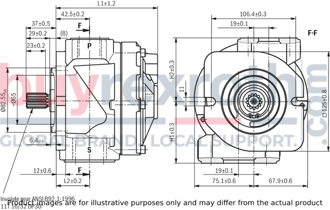
Frame sizes 4 and 5, type ...VU2
PGZ 4-1X/ … RT07VU2
PGZ 5-1X/ … RT07VU2
Drive shaft geared,
SAE 2-hole mounting flange
Dimensions in mm
|
Type |
NG |
Part number |
L1 |
L2 |
H1 |
H2 |
S1) |
P1) |
|
PGZ4-1X/020RT07VU2 |
R901230021 |
116,5 mm |
42,5 mm |
77,4 mm |
79,6 mm |
1 1/2“ |
1“ |
|
|
PGZ4-1X/032RT07VU2 |
R901230025 |
121,5 mm |
42,5 mm |
77,4 mm |
79,6 mm |
1 1/2“ |
1“ |
|
|
PGZ4-1X/040RT07VU2 |
R901230029 |
125 mm |
42,5 mm |
77,4 mm |
79,6 mm |
1 1/2“ |
1“ |
|
|
PGZ4-1X/050RT07VU2 |
R901230033 |
129 mm |
42,5 mm |
77,4 mm |
79,6 mm |
1 1/2“ |
1“ |
|
|
PGZ4-1X/063RT07VU2 |
R901230037 |
134 mm |
42,5 mm |
77,4 mm |
79,6 mm |
1 1/2“ |
1“ |
|
|
PGZ4-1X/080RT07VU2 |
R901230041 |
142 mm |
42,5 mm |
77,4 mm |
79,6 mm |
1 1/2“ |
1“ |
|
|
PGZ5-1X/063RT07VU2 |
R901230045 |
134 mm |
48,5 mm |
72,9 mm |
76,1 mm |
2“ |
1 1/4“ |
|
|
PGZ5-1X/080RT07VU2 |
R901230049 |
142 mm |
48,5 mm |
72,9 mm |
76,1 mm |
2“ |
1 1/4“ |
|
|
PGZ5-1X/100RT07VU2 |
R901230053 |
150,5 mm |
48,5 mm |
72,9 mm |
76,1 mm |
2“ |
1 1/4“ |
|
|
PGZ5-1X/140RT07VU2 |
R901230057 |
163 mm |
48,5 mm |
72,9 mm |
76,1 mm |
2“ |
1 1/4“ |
|
| 1) | For the exact dimensions see Connections |
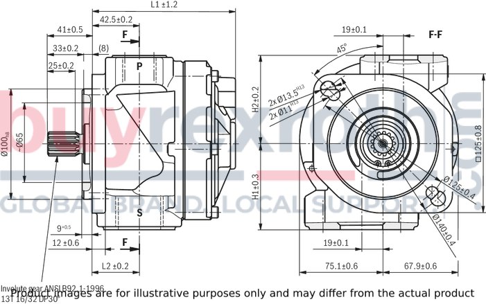
Frame sizes 4 and 5, type ...VB2
PGZ 4-1X/ … RT07VB2
PGZ 5-1X/ … RT07VB2
Drive shaft geared,
ISO 2-hole mounting flange according to ISO 3019-2
(secondary pump for through-drive KB2)
Dimensions in mm

|
Type |
NG |
Part number |
L1 |
L2 |
H1 |
H2 |
S1) |
P1) |
|
PGZ4-1X/020RT07VB2 |
R901230022 |
116,5 mm |
42,5 mm |
77,4 mm |
79,6 mm |
1 1/2“ |
1“ |
|
|
PGZ4-1X/032RT07VB2 |
R901230026 |
121,5 mm |
42,5 mm |
77,4 mm |
79,6 mm |
1 1/2“ |
1“ |
|
|
PGZ4-1X/040RT07VB2 |
R901230030 |
125 mm |
42,5 mm |
77,4 mm |
79,6 mm |
1 1/2“ |
1“ |
|
|
PGZ4-1X/050RT07VB2 |
R901230034 |
129 mm |
42,5 mm |
77,4 mm |
79,6 mm |
1 1/2“ |
1“ |
|
|
PGZ4-1X/063RT07VB2 |
R901230038 |
134 mm |
42,5 mm |
77,4 mm |
79,6 mm |
1 1/2“ |
1“ |
|
|
PGZ4-1X/080RT07VB2 |
R901230042 |
142 mm |
42,5 mm |
77,4 mm |
79,6 mm |
1 1/2“ |
1“ |
|
|
PGZ5-1X/063RT07VB2 |
R901230046 |
134 mm |
48,5 mm |
72,9 mm |
76,1 mm |
2“ |
1 1/4“ |
|
|
PGZ5-1X/080RT07VB2 |
R901230050 |
142 mm |
48,5 mm |
72,9 mm |
76,1 mm |
2“ |
1 1/4“ |
|
|
PGZ5-1X/100RT07VB2 |
R901230054 |
150,5 mm |
48,5 mm |
72,9 mm |
76,1 mm |
2“ |
1 1/4“ |
|
|
PGZ5-1X/140RT07VB2 |
R901230058 |
163 mm |
48,5 mm |
72,9 mm |
76,1 mm |
2“ |
1 1/4“ |
|
| 1) | For the exact dimensions see Connections |
Frame sizes 4 and 5, type ...VB3
PGZ 4-1X/ … RR07VB3
PGZ 5-1X/ … RR07VB3
Drive shaft geared,
ISO 2-hole mounting flange according to ISO 3019-2
(secondary pump for through-drive KB3)
Dimensions in mm
|
Type |
NG |
Part number |
L1 |
L2 |
H1 |
H2 |
S1) |
P1) |
|
PGZ4-1X/020RR07VB3 |
R901230023 |
116,5 mm |
42,5 mm |
77,4 mm |
79,6 mm |
1 1/2“ |
1“ |
|
|
PGZ4-1X/032RR07VB3 |
R901230027 |
121,5 mm |
42,5 mm |
77,4 mm |
79,6 mm |
1 1/2“ |
1“ |
|
|
PGZ4-1X/040RR07VB3 |
R901230031 |
125 mm |
42,5 mm |
77,4 mm |
79,6 mm |
1 1/2“ |
1“ |
|
|
PGZ4-1X/050RR07VB3 |
R901230035 |
129 mm |
42,5 mm |
77,4 mm |
79,6 mm |
1 1/2“ |
1“ |
|
|
PGZ4-1X/063RR07VB3 |
R901230039 |
134 mm |
42,5 mm |
77,4 mm |
79,6 mm |
1 1/2“ |
1“ |
|
|
PGZ4-1X/080RR07VB3 |
R901230043 |
142 mm |
42,5 mm |
77,4 mm |
79,6 mm |
1 1/2“ |
1“ |
|
|
PGZ5-1X/063RR07VB3 |
R901230047 |
134 mm |
48,5 mm |
72,9 mm |
76,1 mm |
2“ |
1 1/4“ |
|
|
PGZ5-1X/080RR07VB3 |
R901230051 |
142 mm |
48,5 mm |
72,9 mm |
76,1 mm |
2“ |
1 1/4“ |
|
|
PGZ5-1X/100RR07VB3 |
R901230055 |
150,5 mm |
48,5 mm |
72,9 mm |
76,1 mm |
2“ |
1 1/4“ |
|
|
PGZ5-1X/140RR07VB3 |
R901230059 |
163 mm |
48,5 mm |
72,9 mm |
76,1 mm |
2“ |
1 1/4“ |
|
| 1) | For the exact dimensions see Connections |
Ports
Porting pattern suction port “S”
Dimensions in mm
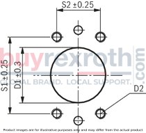
Porting pattern pressure port “P”
Dimensions in mm

|
BG |
Porting pattern / suction port S |
D1 |
D2 |
S1 |
S2 |
Porting pattern / pressure port P |
D3 |
D4 |
P1 |
P2 |
|
4 |
1 1/2“ |
Ø38,1 mm |
M12; 21 mm |
69,9 mm |
35,7 mm |
1“ |
Ø25,4 mm |
M10; 16 mm |
52,4 mm |
26,2 mm |
|
5 |
2“ |
Ø50,8 mm |
M12; 21 mm |
77,8 mm |
42,9 mm |
1 1/4“ |
Ø31,8 mm |
M10; 18 mm |
58,7 mm |
30,2 mm |
1. General information
This project planning information refers to the specific properties of the Rexroth PGZ.-1X gerotor pump. Comprehensive general information and suggestions are contained in the Hydraulics Trainer, volume 3 "Project planning information and design of hydraulic systems", RE 00281.
1.1 Intended use
Rexroth gerotor pumps are intended for use in cooling, filter and lubricating circuits in machine and plant construction. During project planning, the basic principles of the EU Machinery Directive or comparable national regulations outside the EU must be observed. They must not be used in potentially explosive environments in accordance with directive 94/9/EC (ATEX). Use as hydraulic motor is not admissible!
1.2 Technical data
The plant or machine manufacturer must ensure compliance with the admissible technical data and operating conditions. The pump itself does not contain a device to prevent operation outside the admissible data.
All specified technical performance features are average values and apply with the specified boundary conditions. In case of modifications to the basic conditions (e.g. viscosity), the technical data may change as well. Distribution corresponding to the relevant state-of-the-art is possible.
Operating the pump outside of the admissible Technical data is possible to a certain extent, however, this requires the explicit written approval by Bosch Rexroth.
2. Hydraulic project planning
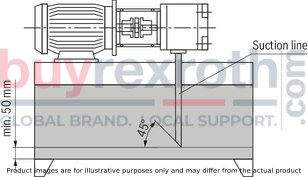
2.1 Place of installation
When installing the pump more than 10 m below the tank, the reduction of the inlet pressure to the maximum admissible value must be ensured by means of additional measures.
2.2 Suction line
The line cross-sections must be rated for the designed flows in a manner that an ideal suction speed of 0.6 to 1.2 m/s is achieved on average. The suction speed must not exceed a maximum value of 2 m/s.
The suction cross-sections at the pump itself are designed for the maximum flow and can therefore only be used as reference. In case of continuous operation with speeds lower than the admissible maximum speed, the suction tube diameter is to be dimensioned smaller than the suction port of the pump in accordance with the actual suction speed.
All in all, the suction line is to be designed so that the admissible input operating pressure is complied with (0.7 to 2 bar abs.)! Bends and the combination of the suction pipes of several pumps are to be avoided.
If suction filters must be used, make sure that the lowest admissible inlet operating pressure is not exceeded on the system side, even if the filter is contaminated.
Please ensure air tightness of the transitions and dimensional stability of the suction tube to the external air pressure.
The immersion depth of the suction pipe should be as large as possible. Dependent on the internal tank pressure, the viscosity of the hydraulic fluid and the flow ratios within the tank, no vortex must be formed even during maximum flow. Otherwise, there is the risk that air is sucked in.
We recommend selecting suction pipes according to AB 23-03.
Dimensions in mm
2.3 Pressure limitation
The PGZ gerotor pump does not comprise any device for compliance with the maximum operating pressure. Setting and limiting the admissible operating pressure has to be ensured on the system side.
3. Mechanical project planning
3.1 Disassembly and installation option
For disassembling and mounting the pump on the drive, accessibility has to be ensured on the system side. Screws of property class 8.8 or 10.9 have to be provided for mounting purposes.
3.2 Mounting
The screws must be accessible on the machine side so that the required tightening torque can be applied. The tightening torque of the screws is based on the operating conditions and involved elements of the
screw connection and has to be specified by the manufacturer in the power unit, machine or system project planning.
3.3 Required power unit functions
Hydraulic power units should at least be equipped with the following features:
Tanks, the internal pressure of which corresponds to the ambient pressure in accordance with the design, have to be equipped with breathing filters for pressure compensation purposes. The hydraulic fluid should only be filled in using filling connections excluding filling with unfiltered hydraulic fluid. The ingress of contamination or humidity must be avoided. In case of use in highly contaminated environments, the tank must to this end be pre-tensioned by means of air pressure. If cleansing of the external tank side is intended or to be expected during the period of use, tank fittings for pipes, lines, or hoses have to be selected, which ensure safe sealing against external pressurization with water jet.
3.4. Environmental conditions
When operating the pump in salt-containing or corrosive environments or when pressure loading with strongly abrasive substances is possible, it has to be ensured on the system side that the shaft seal ring and the sealing area of the shaft do not make direct contact with the environment and that the pump is provided with suitable corrosion protection.
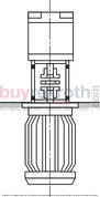
3.5 Installation positions
B3

B5

V1
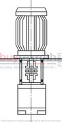
IM V2
4. Maintenance schedule and operational safety
For safe operation and a long life cycle of the pump, a maintenance schedule has to be developed for the power unit, the machine, or the system. The maintenance schedule must ensure that the intended or admissible operating conditions of the pump are complied with over the entire period of use.
In particular, compliance with the following operating parameters has to be ensured:
the required oil cleanliness the operating temperature range the hydraulic fluid filling levelFurthermore, the pump and the system have to be checked for modifications of the following parameters on a regular basis:
Vibrations Noise Temperature pump – hydraulic fluid in the tank Foam formation in the tank Leak-tightness Operating pressure for use in lubrication systemsModifications of these parameters indicate wear of components (e.g. drive motor, coupling, pump, etc.). The cause must be identified and remedied immediately. In order to achieve high operational safety of the pump in the machine or system, we recommend checking the parameters mentioned above continuously and automatically
and shutting the system off automatically in case of modifications exceeding the usual fluctuations in the intended operating range.
Plastic components of drive couplings should be replaced regularly, however, after 5 years at the latest. The relevant manufacturer's specifications must be considered and be given priority.
For preventive maintenance of the pump, we recommend having the seals replaced after a maximum operating time of 5 years by an authorized Bosch Rexroth service company.
5. Accessories
5.1 SAE connection flanges
We recommend selecting the SAE flanges for suction and pressure port according to AB 22-15 (with welded connection) or AB 22-13 (with threaded connection).
5.2 Other accessories
To install the Rexroth PGZ.-1X gerotor pump on electric motors, we recommend selecting the pump carriers according to AB 41-20 and torsionally flexible couplings according to AB 33-22.
Notice!
Please also observe the following documentation:
Data sheet RE 07008 General information on hydraulic products Data sheet RE 07900 General information on assembly, commissioningand maintenance of hydraulic systems
Data sheet RE 90220 General information on hydraulic fluids on mineral oil basisRelated Products
R901230029
$2,206.45 USD
R901230024
$2,095.98 USD

R901252670
$2,265.31 USD
R901230033
$2,473.87 USD

R901253321
$2,903.39 USD


