


Manufacturer: Bosch Rexroth
Material #: R901089559
Model : VT-VPCD-1-1X/V0/1-P-1
***Disclaimer: The following summary contains information gathered from various sources such as product descriptions, technical specifications and catalogs. While efforts have been made to provide accurate details, inaccuracies may occur. It is advised to verify all information by contacting Bosch Rexroth directly.***
The Bosch Rexroth VT-VPCD-1-1X/V0/1-P-1 (R901089559) is a state-of-the-art control electronics module designed for precise adjustment of axial piston pumps, particularly the AVS type with HS control. This module is integral in managing the swivel angle and pressure control, as well as power limitation, through an electrically controlled proportional valve. It uses advanced feedback systems including an inductive position transducer for swash plate positioning and a pressure transducer for accurate pressure measurement.
The VT-VPCD-1-1X/V0/1-P-1 ensures dynamic performance by calculating the actual power value from the swivel angle and pressure data, with software ensuring that the most appropriate controller is active according to the working point. In its default state, the valve control spool maintains a central position until there's a demand from superior controllers to adjust flow or pressure.
This module's control electronics are built on a double-sided printed circuit board featuring a microcontroller at its core, which orchestrates the entire process and executes controller functions. It stores configuration data and command values in non-volatile FLASH memory. Up to 16 parameter sets can be stored and easily accessed through binary-coded digital inputs.
For precise control inputs, it includes differential inputs for analog command value presetting alongside digital call-up command values. The output stage is regulated based on these inputs to ensure optimal performance of the axial piston pump. The VT-VPCD-1-1X/V0/1-P-1 also offers modes for pressure control that can work with either one or two pressure sensors, catering to both open and closed circuit applications.
Moreover, it features diagnostic capabilities that identify faults such as cable breaks or short circuits in sensor readings or deviations in control loops. Errors are indicated via output signals and can be displayed for quick troubleshooting.
Parameterization and diagnosis are facilitated through a serial interface that allows configuration of pump size, leakage oil correction, sequence control activation/deactivation, switching outputs, test outputs via BODAC software. It also supports masterslave functionality and mooring capability with optional PROFIBUS connectivity.
Overall, this Bosch Rexroth electronic module represents an advanced solution for controlling variable displacement axial piston pumps within various hydraulic systems requiring precise motion control and power management.
This product is not available. CLICK HERE to create a support ticket for us to locate your part or a suitable replacement
Functional description using the A4VS axial piston pump with HS4 control as example
The swivel angle and pressure control as well as the power limitation of the A4VS… variable displacement pump are realized by an electrically controlled proportional valve (1). Via the actuating piston (2) of the pump, this valve determines the position of the swash plate (3).
If the pump does not rotate, in case of depressurized high pressure and actuating system and if enable is not operated, the swash plate is held in the "Zero" swivel angle position by the spring centering.
The position of the swash plate is determined by an inductive position transducer (4), the actual pressure value is recorded by a pressure transducer. Both actual values are supplied to the VT-VPCD control electronics and linked with each other by the software.
The actual power value is calculated from the product of actual pressure value and actual swivel angle value. The controller software ensures by means of a minimum value generator that the controller corresponding to the working point is always active.
In the static condition (i.e. swivel angle command value equals actual swivel angle value, power command value equals actual power value or pressure command value equals actual pressure value) the valve control spool is in central position.
If the superior controllers demand e.g. an increase in the swivel angle (corresponds to an increase in the flow), the valve control spool must be deflected out of the central position until the swivel angle has reached the required value.
The sectional drawing shows the A4VS… variable displacement pump with HS4 control; the proportional valve (1) is controlled using the VT-VPCD control electronics.
Notice for the HS4 control:
With de-energized proportional valve and pump with clockwise rotation and if the set pressure is available, the pump swivels to swivel angle α = 0 (A4VSO design) or α = –100 % (A4VSG design).

Functional description of the control electronics
The control electronics is set-up as printed circuit board, fitted on both sides. It comprises a switching power supply unit [1] creating all internally required voltages.
The central unit is a microcontroller controlling the entire process and realizing the controller functions. Data for configuration, command values and parameters are stored in a FLASH in a non-volatile form.
Four binarily coded digital inputs are used to call up parameter sets (command values) from the memory in which you can store a maximum of 16 sets. A call-up activates a command value for the swivel angle, the pressure and the power limitation as well as ramp times for swivel angle and pressure.
More control inputs have the following functions:
"Command value valid":
Enabling of the parameter set addressed by the current call-up (H active)
"Enable":
Activation of the control (H active)
Please note:
H active = activate at high level
Via the differential inputs AI7, AI5 and AI4 [3], the analog command value presetting for the swivel angle, the pressure and the maximum power are specified. With a positive swivel angle command value, the pump swivels in "counterclockwise" swivel direction (= direction of flow P → B). The digital call-up command values are added to the analog command values; the total of both command values is supplied to the controller input via the relevant ramp generators.
The controller output signal controls the output stage [6] depending on the command/actual value differences.
The position of the valve control spool [11], the swivel angle of the variable displacement pump [12a, 12b or 12c] and the system pressure [13] are measured and supplied to the control loop via evaluation electronics [7].
Modes for pressure control
Depending on the configuration, the pressure controller works with one or two pressure sensors.
Open circuit:
1 sensor, optionally current or voltage
Closed circuit:
2 sensors, optionally current or voltage
In the closed circuit, both pressure sensors are evaluated. As soon as the control electronics is in pressure control, the larger of the two pressures determines the control behavior. To compensate control deviations (pressure command value - actual pressure value), the pressure controller can also swivel the pump to the opposite side as well as beyond its specified swivel angle command value.
The switching outputs are configured via BODAC. The following functions may be selected:
DO1: Swivel angle control active
DO2: Pressure control active
DO3: Power limitation active
DO4 Slave mode active
DO5: Swivel angle in the accuracy window
DO6: Pressure in the accuracy window
DO7: Rectangular 32 Hz
The test output (b26 or measuring socket X1) is also configured via BODAC. It is used for the analog output of internal variables.
Enable and error messages
Setting the enable input activates the control. If no command value call-up is activated, parameter set 0 is set.
Error logics identify the following faults:
Cable break or short-circuit in the actual valve value recording
Cable break or short-circuit in actual swivel angle value acquisition
Cable break at the pressure transducer (only current interface)
Closed-loop errors (i.e. control deviations between swivel angle command value and actual swivel angle value)
An error is indicated at output d22. The "OK" message goes out, signal level is 0 V.
Errors are also shown at the display.
Parameterization and diagnosis
Using the serial interface [2], the pump size is selected and the leakage oil correction and the sequence control are activated or deactivated and switching outputs and the test output are configured via BODAC at the front-side D-Sub socket. Via the local bus, up to 32 control electronics can be connected. Via BODAC, every control electronics is assigned a bus address. Reconnection of the serial interface cable is not required. More information in document 30028-01-B.
[ ] = Assignment to the block diagrams
VT-VPCD control electronics in connection with the axial piston pump A4VS…HS4 or A2V…EO4 serves for realization of all electrical functions required for adjustment. Parameterization is effected via a serial interface.
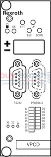
LED displays
|
|
Enable activated |
|
OK |
Ready for operation |
|
± |
Sign display for 4-digit indicator |
|
4-digit alphanumerical display |
Indicator for configuration, parameterization and diagnosis |
|
I1 … I4 |
Binary command value call-ups |
|
I5 |
Slave mode |
|
I6 |
Command value valid |
|
I7 … I8 |
not assigned |
|
O1 |
Swivel angle control enabled |
|
O2 |
Pressure control enabled |
|
O3 |
Power limitation active |
|
O4 |
Slave mode active |
|
O5 |
Swivel angle in the accuracy window |
|
O6 |
Pressure in the accuracy window |
|
O7 |
Rectangular signal 32 Hz |
Measuring sockets
|
X1 |
Process signal (selection via BODAC) |
|
X2 |
Process signal (selection via BODAC) |
|
⊥ |
Reference potential |
VT-VPCD-1-1X/V0/1-0-1 for A4VS...HS4 axial piston pump with AWX F004 D01 swivel angle sensor
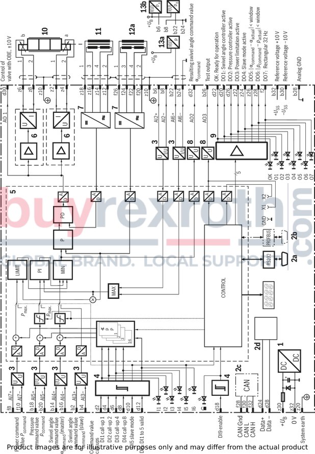
VT-VPCD-1-1X/V0/1-0-1 for A4VS...HS4 axial piston pump with AWX F004 D01 swivel angle sensor
|
1 |
Power supply unit |
|
2a |
Serial interface |
|
2b |
PROFIBUS interface, optional |
|
2c |
CAN bus interface, optional |
|
2d |
Local bus |
|
3 |
Voltage or current input |
|
4 |
Level converter |
|
5 |
Microcontroller |
|
6 |
Power output stage |
|
7 |
Oscillator/demodulator |
|
8 |
Voltage output |
|
9 |
Output driver |
|
10 |
Proportional valve |
|
11 |
Position transducer of valve |
|
12a |
Swivel angle sensor of pump |
|
13a |
Pressure transducer (open circuit) |
|
13b |
Pressure transducer (closed circuit) |
VT-VPCD-1-1X/V0/1-0-1 for axial piston pump A2V…EO4 (housing pump) with swivel angle sensor MCP-40/4742

VT-VPCD-1-1X/V0/1-0-1 for A4VS...HS4 axial piston pump with AWX F004 D01 swivel angle sensor
|
1 |
Power supply unit |
|
2a |
Serial interface |
|
2b |
PROFIBUS interface, optional |
|
2c |
CAN bus interface, optional |
|
2d |
Local bus |
|
3 |
Voltage or current input |
|
4 |
Level converter |
|
5 |
Microcontroller |
|
6 |
Power output stage |
|
7 |
Oscillator/demodulator |
|
8 |
Voltage output |
|
9 |
Output driver |
|
10 |
Proportional valve |
|
11 |
Position transducer of valve |
|
12a |
Swivel angle sensor of pump |
|
13a |
Pressure transducer (open circuit) |
|
13b |
Pressure transducer (closed circuit) |
VT-VPCD-1-1X/V100/1-0-1 for axial piston pump A2V…EO4 (installation pump) with swivel angle sensor DK 100
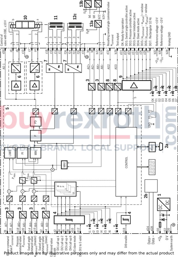
|
1 |
Power supply unit |
|
2a |
Serial interface |
|
2b |
Local bus |
|
3 |
Voltage or current input |
|
4 |
Level converter |
|
5 |
Microcontroller |
|
6 |
Power output stage |
|
7 |
Oscillator/demodulator |
|
8 |
Voltage output |
|
9 |
Output driver |
|
10 |
Proportional valve |
|
11 |
Position transducer of valve |
|
12c |
Swivel angle sensor of pump |
|
13a |
Pressure transducer (open circuit) |
|
13b |
Pressure transducer (closed circuit) |
Pin assignment of the male multipoint connector
VT-VPCD-1-1X/V0/1-0-1 for A4VS...HS4 axial piston pump with AWX F004 D01 swivel angle sensor
|
Row d |
Row b |
|||||
|
Pin |
Signal |
Description |
Pin |
Signal |
Description |
|
|
2 |
DI1 |
Binary command value call-up 1 |
2 |
AI3+ |
Slave swivel angle command value (in case of slave operation) |
|
|
4 |
DI2 |
Binary command value call-up 2 |
4 |
AI3- |
Slave swivel angle command value, reference |
|
|
6 |
DI3 |
Binary command value call-up 4 |
6 |
AI2+ |
Actual pressure value pA, (I or U) |
|
|
8 |
DI4 |
Binary command value call-up 8 |
8 |
AI2- |
Actual pressure value pA, reference |
|
|
10 |
DI5 |
Slave mode |
10 |
n. c. |
not assigned |
|
|
12 |
DI6 |
Command value valid |
12 |
n. c. |
not assigned |
|
|
14 |
n. c. |
not assigned |
14 |
AI4+ |
Swivel angle command value |
|
|
16 |
n. c. |
not assigned |
16 |
AI4- |
Swivel angle command value, reference |
|
|
18 |
DI9 |
Enable |
18 |
AI5+ |
Pressure command value |
|
|
20 |
DO1 |
Swivel angle control enabled |
20 |
AI5- |
Pressure command value, reference |
|
|
22 |
OK |
OK output |
22 |
AI6+ |
Actual pressure value pB, (I or U) |
|
|
24 |
Data+ |
Local bus |
24 |
AI6- |
Actual pressure value pB, reference |
|
|
26 |
DO2 |
Pressure control enabled |
26 |
AO3 |
Test output (measuring socket X1) |
|
|
28 |
Data- |
Local bus |
28 |
AGND |
Analog GND |
|
|
30 |
AO1 |
Control of valve with OBE |
30 |
REF- |
-10 V |
|
|
32 |
AO2 |
Resulting swivel angle command value for master/slave operation |
32 |
REF+ |
+10 V |
|
|
Row z |
Row f |
|||||
|
Pin |
Signal |
Description |
Pin |
Signal |
Description |
|
|
2 |
MA+ |
Solenoid A+ |
2 |
DO7 |
Rectangular signal 32 Hz |
|
|
4 |
MA- |
Solenoid A- |
4 |
n. c. |
not assigned |
|
|
6 |
MB+ |
Solenoid B+ |
6 |
n. c. |
not assigned |
|
|
8 |
MB- |
Solenoid B- |
8 |
AI7+ |
Power command value |
|
|
10 |
Shield |
Shield |
10 |
AI7- |
Power command value, reference |
|
|
12 |
L1O- |
Position transducer of valve, feed -, pin 2 |
12 |
n. c. |
not assigned |
|
|
14 |
L1I- |
Position transducer of valve, actual value –, pin 4 |
14 |
n. c. |
not assigned |
|
|
16 |
L1I+ |
Position transducer of valve, actual value +, pin 3 |
16 |
n. c. |
not assigned |
|
|
18 |
L1O+ |
Position transducer of valve, feed +, pin 1 |
18 |
n. c. |
not assigned |
|
|
20 |
System earth |
System earth |
20 |
L2O- |
Swivel angle sensor of pump, feed –, pin 2 |
|
|
22 |
DO3 |
Power limitation active |
22 |
L2I- |
Swivel angle sensor of pump, actual value –, pin 4 |
|
|
24 |
DO4 |
Slave mode active |
24 |
L2I+ |
Swivel angle sensor of pump, actual value +, pin 3 |
|
|
26 |
DO5 |
|αcommand – αactual| < window |
26 |
L2O+ |
Swivel angle sensor of pump, feed +, pin 1 |
|
|
28 |
DO6 |
|pcommand – pactual| < window |
28 |
CAN Gnd |
CAN bus reference |
|
|
30 |
UB |
Operating voltage |
30 |
CAN L |
CAN bus input/output |
|
|
32 |
L0 |
Ground 0 V |
32 |
CAN H |
CAN bus input/output |
|
Pin assignment of the male multipoint connector
VT-VPCD-1-1X/V0/1-0-1 for A2V...EO4 axial piston pump (housing pump) with MCP-40/4742 swivel angle sensor
|
Row d |
Row b |
|||||
|
Pin |
Signal |
Description |
Pin |
Signal |
Description |
|
|
2 |
DI1 |
Binary command value call-up 1 |
2 |
AI3+ |
Slave swivel angle command value (in case of slave operation) |
|
|
4 |
DI2 |
Binary command value call-up 2 |
4 |
AI3- |
Slave swivel angle command value, reference |
|
|
6 |
DI3 |
Binary command value call-up 4 |
6 |
AI2+ |
Actual pressure value pA, (I or U) |
|
|
8 |
DI4 |
Binary command value call-up 8 |
8 |
AI2- |
Actual pressure value pA, reference |
|
|
10 |
DI5 |
Slave mode active |
10 |
AI1+ |
Swivel angle sensor of pump, pin 2 |
|
|
12 |
DI6 |
Command value valid |
12 |
AI1- |
Swivel angle sensor of pump, pin 5 |
|
|
14 |
n. c. |
not assigned |
14 |
AI4+ |
Swivel angle command value |
|
|
16 |
n. c. |
not assigned |
16 |
AI4- |
Swivel angle command value, reference |
|
|
18 |
DI9 |
Enable |
18 |
AI5+ |
Pressure command value |
|
|
20 |
DO1 |
Swivel angle control enabled |
20 |
AI5- |
Pressure command value, reference |
|
|
22 |
OK |
OK output |
22 |
AI6+ |
Actual pressure value pB, (I or U) |
|
|
24 |
Data+ |
Local bus |
24 |
AI6- |
Actual pressure value pB, reference |
|
|
26 |
DO2 |
Pressure control enabled |
26 |
AO3 |
Test output (measuring socket X1) |
|
|
28 |
Data- |
Local bus |
28 |
AGND |
Analog GND / Swivel angle sensor of pump, pin 5 |
|
|
30 |
AO1 |
Control of valve with OBE |
30 |
REF- |
-10 V |
|
|
32 |
AO2 |
Resulting swivel angle command value for master/slave operation |
32 |
REF+ |
+10 V / swivel angle sensor of pump, pin 4 |
|
|
Row z |
Row f |
|||||
|
Pin |
Signal |
Description |
Pin |
Signal |
Description |
|
|
2 |
MA+ |
Solenoid A+ |
2 |
DO7 |
Rectangular signal 32 Hz |
|
|
4 |
MA- |
Solenoid A- |
4 |
n. c. |
not assigned |
|
|
6 |
MB+ |
Solenoid B+ |
6 |
n. c. |
not assigned |
|
|
8 |
MB- |
Solenoid B- |
8 |
AI7+ |
Power command value |
|
|
10 |
Shield |
Shield |
10 |
AI7- |
Power command value, reference |
|
|
12 |
L1O- |
Position transducer of valve, feed -, pin 2 |
12 |
n. c. |
not assigned |
|
|
14 |
L1I- |
Position transducer of valve, actual value –, pin 4 |
14 |
n. c. |
not assigned |
|
|
16 |
L1I+ |
Position transducer of valve, actual value +, pin 3 |
16 |
n. c. |
not assigned |
|
|
18 |
L1O+ |
Position transducer of valve, feed +, pin 1 |
18 |
n. c. |
not assigned |
|
|
20 |
System earth |
System earth |
20 |
n. c. |
not assigned |
|
|
22 |
DO3 |
Power limitation active |
22 |
n. c. |
not assigned |
|
|
24 |
DO4 |
Slave mode active |
24 |
n. c. |
not assigned |
|
|
26 |
DO5 |
|αcommand – αactual| < window |
26 |
n. c. |
not assigned |
|
|
28 |
DO6 |
|pcommand – pactual| < window |
28 |
CAN Gnd |
CAN bus reference |
|
|
30 |
UB |
Operating voltage |
30 |
CAN L |
CAN bus input/output |
|
|
32 |
L0 |
Ground 0 V |
32 |
CAN H |
CAN bus input/output |
|
Pin assignment of the male multipoint connector
VT-VPCD-1-1X/V100/1-0-1 for A2V...EO4 axial piston pump (installation pump) with DK 100 swivel angle sensor
|
Row d |
Row b |
|||||
|
Pin |
Signal |
Description |
Pin |
Signal |
Description |
|
|
2 |
DI1 |
Binary command value call-up 1 |
2 |
AI3+ |
Slave swivel angle command value (in case of slave operation) |
|
|
4 |
DI2 |
Binary command value call-up 2 |
4 |
AI3- |
Slave swivel angle command value, reference |
|
|
6 |
DI3 |
Binary command value call-up 4 |
6 |
n. c. |
not assigned |
|
|
8 |
DI4 |
Binary command value call-up 8 |
8 |
n. c. |
not assigned |
|
|
10 |
DI5 |
Slave mode active |
10 |
n. c. |
not assigned |
|
|
12 |
DI6 |
Command value valid |
12 |
n. c. |
not assigned |
|
|
14 |
n. c. |
not assigned |
14 |
AI4+ |
Swivel angle command value |
|
|
16 |
n. c. |
not assigned |
16 |
AI4- |
Swivel angle command value, reference |
|
|
18 |
DI9 |
Enable |
18 |
AI5+ |
Pressure command value |
|
|
20 |
DO1 |
Swivel angle control enabled |
20 |
AI5- |
Pressure command value, reference |
|
|
22 |
OK |
OK output |
22 |
AI6+ |
Actual pressure value pB, (I or U) |
|
|
24 |
Data+ |
Local bus |
24 |
AI6- |
Actual pressure value pB, reference |
|
|
26 |
DO2 |
Pressure control enabled |
26 |
AO3 |
Test output (measuring socket X1) |
|
|
28 |
Data- |
Local bus |
28 |
AGND |
Analog GND |
|
|
30 |
AO1 |
Control of valve with OBE |
30 |
REF- |
-10 V |
|
|
32 |
AO2 |
Resulting swivel angle command value for master/slave operation |
32 |
REF+ |
+10 V |
|
|
Row z |
Row f |
|||||
|
Pin |
Signal |
Description |
Pin |
Signal |
Description |
|
|
2 |
MA+ |
Solenoid A+ |
2 |
DO7 |
Rectangular signal 32 Hz |
|
|
4 |
MA- |
Solenoid A- |
4 |
n. c. |
not assigned |
|
|
6 |
MB+ |
Solenoid B+ |
6 |
n. c. |
not assigned |
|
|
8 |
MB- |
Solenoid B- |
8 |
AI7+ |
Power command value |
|
|
10 |
Shield |
Shield |
10 |
AI7- |
Power command value, reference |
|
|
12 |
L1O- |
Position transducer of valve, feed -, pin 2 |
12 |
n. c. |
not assigned |
|
|
14 |
L1I- |
Position transducer of valve, actual value –, pin 4 |
14 |
n. c. |
not assigned |
|
|
16 |
L1I+ |
Position transducer of valve, actual value +, pin 3 |
16 |
n. c. |
not assigned |
|
|
18 |
L1O+ |
Position transducer of valve, feed +, pin 1 |
18 |
n. c. |
not assigned |
|
|
20 |
System earth |
System earth |
20 |
L2O- |
Swivel angle sensor of pump, actual value –, pin 4 |
|
|
22 |
DO3 |
Power limitation active |
22 |
L2I- |
Swivel angle sensor of pump, actual value +, pin 3 |
|
|
24 |
DO4 |
Slave mode active |
24 |
L2I+ |
Swivel angle sensor of pump, feed –, pin 2 |
|
|
26 |
DO5 |
|αcommand – αactual| < window |
26 |
L2O+ |
Swivel angle sensor of pump, feed +, pin 1 |
|
|
28 |
DO6 |
|pcommand – pactual| < window |
28 |
n. c. |
not assigned |
|
|
30 |
UB |
Operating voltage |
30 |
n. c. |
not assigned |
|
|
32 |
L0 |
Ground 0 V |
32 |
n. c. |
not assigned |
|
Pin assignment of the RS 232 socket

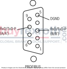
Pin assignment of the PROFIBUS socket
Dimensions in mm

Dimensions in mm

Related Products
R987272191
$10,850.00 USD
R901102706
$457.00 USD
R901387684
$8,341.00 USD
R901099789
$549.00 USD
R901107122
$593.00 USD


