


HY-CHECK VALVE M-SR 20 KE30-1X/V
Manufacturer: Bosch Rexroth
Material #: R900420865
Model : M-SR 20 KE30-1X/V
***Disclaimer: The following summary contains information gathered from various sources such as product descriptions, technical specifications and catalogs. While efforts have been made to provide accurate details, inaccuracies may occur. It is advised to verify all information by contacting Bosch Rexroth directly.***
The Bosch Rexroth M-SR 20 KE30-1X/V (R900420865) is a high-quality check valve designed for hydraulic applications that require leakage-free blocking in one direction. It is a cartridge design that can be integrated into block designs, either as an angle valve or a straight-through valve. This product is part of the MSR family and features a poppet type spool for reliable operation.
With its direct acting mechanism, the M-SR 20 KE30-1X/V ensures consistent performance without the need for pressure presetting. The nominal flow and maximum flow capabilities of this check valve are aligned with its intended applications, ensuring efficient fluid control within hydraulic systems. The maximum operating pressure it can withstand highlights its robustness and suitability for demanding environments.
The sealing material used in this model is FKM, known for its high resistance to heat and chemicals, contributing to the durability and longevity of the valve. Furthermore, it supports a variety of hydraulic fluids including HL, HLP, HETG, HEES, HEPG, and HFDU, offering versatility in different hydraulic systems.
This Bosch Rexroth check valve is designed to cater to various cracking pressures which are optionally available to suit specific application requirements. Its size and component series X designation indicate its compatibility with different system configurations. The weight specification suggests ease of handling during installation or maintenance procedures.
In summary, the M-SR 20 KE30-1X/V provides reliable performance in controlling fluid direction within hydraulic systems while offering flexibility in terms of installation type and compatibility with various hydraulic fluids.
$335.84 USD
More are expected on October 7, 2024
Status: This product is temporarily out of stock.
Qty: Delivered as early as October 7, 2024 when ordered in
This product is eligible for factory repair.
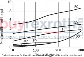
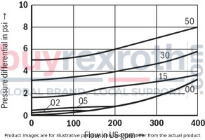
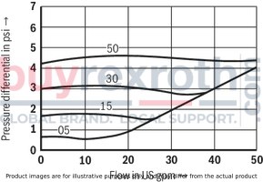
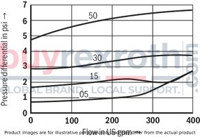
Angle valve (measured with HLP46, ϑOil = 40 ±5 °C)
Pressure differential Δp dependent on the flow qV at cracking pressure
Size 8
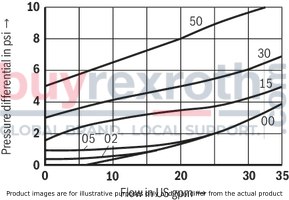
Pressure differential Δp dependent on the flow qV at cracking pressure
Size 10
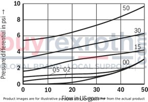
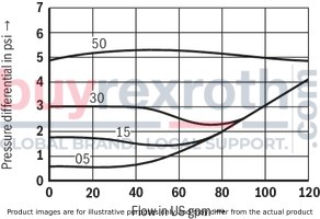
Pressure differential Δp dependent on the flow qV at cracking pressure
Size 15
Pressure differential Δp dependent on the flow qV at cracking pressure
Size 20
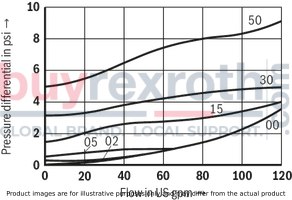
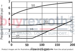
Pressure differential Δp dependent on the flow qV at cracking pressure
Size 25
Pressure differential Δp dependent on the flow qV at cracking pressure
Size 30
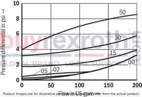
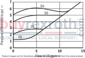
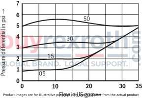
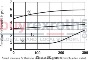
Straight-through valve (measured with HLP46, ϑOil = 40 ±5 °C)
Pressure differential Δp dependent on the flow qV at cracking pressure
Size 6
Pressure differential Δp dependent on the flow qV at cracking pressure
Size 8
Pressure differential Δp dependent on the flow qV at cracking pressure
Size 10
Pressure differential Δp dependent on the flow qV at cracking pressure
Size 15
Pressure differential Δp dependent on the flow qV at cracking pressure
Size 20
Pressure differential Δp dependent on the flow qV at cracking pressure
Size 25
Pressure differential Δp dependent on the flow qV at cracking pressure
Size 30
With spring

Without spring

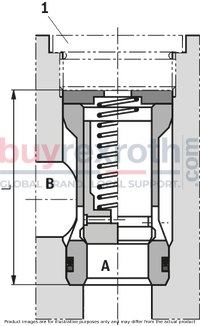
Angle valve "KE"
Dimensions in mm
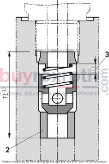
Straight-through valve "KD"
Dimensions in mm
| 1) | For dimensions, see installation bores |
|
NG |
L-0,1 |
|
mm |
|
| 6 | - |
| 8 | 36.3 |
| 10 | 39.3 |
| 15 | 45.8 |
| 20 | 55.3 |
| 25 | 74.3 |
| 30 | 83.3 |
|
1 |
Plug screws, separate order, see "Accessories" |
|
2 |
Seat with -60 °C shrink-fitted |
|
3 |
Poppet stroke |
Installation bores
Installation bore: Angle valve "KE" – plug screw according to ZN 10001
Dimensions in mm
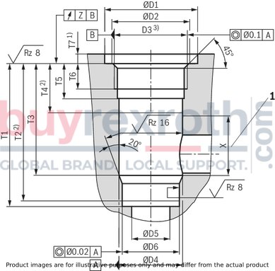
| 1) | Dimensions for countersinking the screw head. For lower installation of the installation kit, dimension T7 has to be extended accordingly. |
| 2) | Depth of fit |
| 3) | Pipe thread "G" according to ISO 228/1 |
|
1 |
Range for outlet bore |
|
NG |
pN |
ØD1 |
ØD2 |
D3 |
ØD4H8 |
ØD5 |
ØD6H7 |
T1 |
T2 |
T3 |
T4 |
T5 |
T6 |
T7 |
X |
Z |
||
|
bar |
mm |
mm |
mm |
mm |
mm |
mm |
mm |
mm |
mm |
mm |
mm |
mm |
mm |
mm |
mm |
mm |
||
| 8 | 420 | 23 | 17.1 | G3/8 | 14 | 8 | 13 | 48.5 | + 0.1 | 47.5 | 38.5 | 20 | 15 | 12 | 6 | + 0.5 | 18 | 0.05 |
| 10 | 420 | 28 | 21.4 | G1/2 | 18 | 10 | 17 | 53.5 | + 0.1 | 52.5 | 43.5 | 24 | 18 | 14 | 6 | + 0.5 | 19 | 0.05 |
| 15 | 420 | 33 | 26.8 | G3/4 | 24 | 15 | 22 | 62 | + 0.1 | 60.5 | 50 | 26 | 20.5 | 16 | 6 | + 0.5 | 24 | 0.05 |
| 20 | 420 | 41 | 33.8 | G1 | 30 | 20 | 28 | 71.5 | + 0.1 | 70 | 56.5 | 26 | 20.5 | 16 | 7 | + 0.5 | 30 | 0.05 |
| 25 | 250 | 51 | 42.5 | G1 1/4 | 38 | 25 | 36 | 90.5 | + 0.1 | 88 | 72.5 | 28 | 22 | 16 | 7 | + 0.5 | 43 | 0.1 |
| 30 | 250 | 56 | 48.5 | G1 1/2 | 44 | 30 | 42 | 99.5 | + 0.1 | 96.5 | 79.5 | 31 | 22 | 16 | 7 | + 0.5 | 48 | 0.1 |
Notice:
Plug screws, separate order, see "Accessories"
Oiling of plug screws prior to installation is recommended.
Installation bore: Angle valve – plug screw according to RN 143.28 – up to 315 bar
Dimensions in mm

| 1) | Dimensions for countersinking the screw head. For lower installation of the installation kit, dimension T7 has to be extended accordingly. |
| 2) | Depth of fit |
| 3) | Metric ISO fine thread according to DIN 13 |
|
1 |
Range for outlet bore |
|
NG |
pN |
ØD1 |
ØD2H8 |
D3 |
ØD4H8 |
ØD5 |
ØD6H7 |
T1 |
T2 |
T3 |
T4 |
T5 |
T6 |
T7 |
T8 |
X |
||||
|
bar |
mm |
mm |
mm |
mm |
mm |
mm |
mm |
mm |
mm |
mm |
mm |
mm |
mm |
mm |
mm |
mm |
mm |
mm |
||
| 25 | 315 | 56 | + 0.5 | 44 | M42 x 1,5 | 38 | 25 | 36 | 106.5 | + 0.1 | 104 | 88.5 | 45 | 39 | 33 | 5 | + 0.5 | 12 | + 0.2 | 43 |
| 30 | 315 | 62 | + 0.5 | 50 | M48 x 1,5 | 44 | 30 | 42 | 115.5 | + 0.1 | 112.5 | 95.5 | 48 | 39 | 33 | 5 | + 0.5 | 12 | + 0.2 | 48 |
Notice:
Plug screws, separate order, see "Accessories"
To be replaced in case of maintenance.
Installation bore: Angle valve – plug screw according to RN 143.28 – up to 420 bar
Dimensions in mm

| 1) | Dimensions for countersinking the screw head. For lower installation of the installation kit, dimension T7 has to be extended accordingly. |
| 2) | Depth of fit |
| 3) | Metric ISO fine thread according to DIN 13 |
|
1 |
Range for outlet bore |
|
NG |
pN |
ØD1 |
ØD2H8 |
D3 |
ØD4H8 |
ØD5 |
ØD6H7 |
ØD7 |
ØD8 |
T1 |
T2 |
T3 |
T4 |
T5 |
T6 |
T7 |
T8 |
X |
||||
|
bar |
mm |
mm |
mm |
mm |
mm |
mm |
mm |
mm |
mm |
mm |
mm |
mm |
mm |
mm |
mm |
mm |
mm |
mm |
mm |
mm |
||
| 25 | 420 | 51 | + 0.5 | 44 | M42 x 2 | 38 | 25 | 36 | 37.58 | 35.58 | 101.5 | + 0.1 | 100 | 83.5 | 40 | 34 | 27 | 6 | + 0.5 | 7.8 | + 0.2 | 43 |
| 30 | 420 | 61 | + 0.5 | 50 | M48 x 2 | 44 | 30 | 42 | 43.58 | 41.58 | 110.5 | + 0.1 | 108.5 | 90.5 | 43 | 34 | 27 | 6 | + 0.5 | 7.8 | + 0.2 | 48 |
Notice:
Plug screws, separate order, see "Accessories" Oiling of plug screws prior to installation is recommended. From an operating pressure larger 350 bar, the plug screw has to be glued by means of Loctite 243 over the complete thread circumference.Installation bore: Straight-through valve
Dimensions in mm
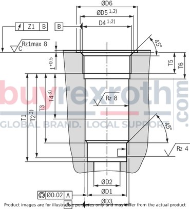
|
NG |
ØD1H7 |
ØD3H8 |
D4 1) |
ØD5 |
D4 2) |
ØD5 |
ØD6 |
T1 |
T2 3) |
T3 |
T4 3) |
T5 |
T6 |
Z |
Poppet stroke |
|||
|
mm |
mm |
mm 1) |
mm |
mm 2) |
mm |
mm |
mm |
mm |
mm |
mm |
mm |
mm |
mm |
mm |
mm |
|||
| 6 | 10 | 11 | G1/4 | 13.6 | ± 0.1 | M14 x 1,5 | 14.4 | ± 0.1 | 25 | 29.8 | - 0.1 | 27.8 | 21.8 | 19 | 12 | 16 | 0.1 | 4 |
| 8 | 13 | 14 | G3/8 | 17.1 | ± 0.1 | M18 x 1,5 | 18.4 | ± 0.1 | 28 | 32.8 | - 0.1 | 30.8 | 22.8 | 18 | 12 | 16 | 0.1 | 4 |
| 10 | 17 | 18 | G1/2 | 21.4 | ± 0.1 | M22 x 1.5 | 22.4 | ± 0.1 | 34 | 38.8 | - 0.1 | 36.8 | 28.8 | 21 | 14 | 19 | 0.1 | 4 |
| 15 | 22 | 24 | G3/4 | 26.8 | ± 0.1 | M27 x 2 | 27.4 | ± 0.1 | 42 | 48.4 | - 0.1 | 46.4 | 36.4 | 27 | 16 | 21 | 0.2 | 5 |
| 20 | 28 | 30 | G1 | 33.8 | ± 0.1 | M33 x 2 | 33.5 | ± 0.1 | 47 | 59 | - 0.1 | 57 | 44 | 29 | 18 | 24 | 0.2 | 5 |
| 25 | 36 | 38 | G1 1/4 | 42.5 | ± 0.1 | M42 x 2 | 42.5 | ± 0.1 | 58 | 73 | - 0.1 | 71 | 55 | 39 | 20 | 26 | 0.2 | 7 |
| 30 | 42 | 44 | G1 1/2 | 48.5 | ± 0.1 | M48 x 2 | 48.5 | ± 0.1 | 65 | 83 | - 0.1 | 81 | 63 | 42 | 22 | 28 | 0.2 | 7 |
| 1) | Pipe thread "G" according to ISO 228/1 |
| 2) | Metric ISO fine thread according to DIN 13 |
| 3) | Depth of fit |
Related Products
R900470298
$374.37 USD
R900424147
$293.16 USD
R900348453
$374.37 USD
R900370858
$579.46 USD
R900487903
$341.32 USD


