


4WRPE10V50S-3X/M/24F1
Manufacturer: Bosch Rexroth
Material #: R901436338
Model : 4WRPE10V50S-3X/M/24F1
***Disclaimer: The following summary contains information gathered from various sources such as product descriptions, technical specifications and catalogs. While efforts have been made to provide accurate details, inaccuracies may occur. It is advised to verify all information by contacting Bosch Rexroth directly.***
The Bosch Rexroth 4WRPE10V50S-3X/M/24F1 (R901436338) is a high-performance directional valve known for its precise control and reliability. This direct-operated valve includes electric position feedback and integrated electronics OBE, ensuring accurate command value comparisons and adjustments in control deviations. The valve setup comprises a robust valve housing, a control spool with compression springs, and an optional electronics protection membrane to safeguard against environmental conditions.
Its functionality is enhanced by the integrated control electronics OBE with an analog interface, which proportionally controls the stroke spool cross-section relative to the command value. This allows for precise positioning of the spool to regulate fluid flow effectively. The valve's design ensures that even in the event of error conditions such as a drop in supply voltage or current command value, the system will de-energize the solenoids to prevent damage.
The inclusion of a damping plate reduces acceleration amplitudes affecting onboard electronics at frequencies above 50 Hz, though its use is not recommended for predominantly low-frequency applications. Additionally, an optional electronics protection membrane can be utilized for operations in challenging environments with high humidity or temperature fluctuations.
This Bosch Rexroth directional valve is suitable for various applications requiring accurate position and velocity control due to its energy efficiency, absence of pilot oil demand, and capability to handle high flows with minimal pressure differential. Its size and component series X are designed to withstand maximum operating pressures up to 350 bar while facilitating nominal flows up to 50 l/min. Safety features include the option of shutting off the second solenoid using an ISA adapter if necessary.
$6,039.00 USD
Availability: Backordered
Ships from US
Qty:
Delivered as early as December 18, 2026
$6,340.95 USD
Availability: Backordered
Ships from CA
Qty:
Delivered as early as December 18, 2026
This product is eligible for factory repair.
4/3 directional valve
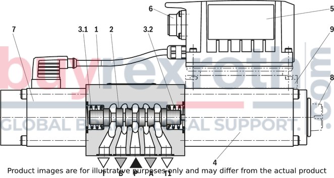
The valve type 4WRPE is a direct operated directional control valve with electric position feedback and integrated electronics (OBE).
Set-up
The valve basically consists of:
Valve housing (1) Control spool (2) with compression springs (3.1 and 3.2) Control solenoid with position transducer (4) (optional with electronics protection membrane (8)) Stroke solenoid (7) Integrated control electronics (OBE) (5) with analog interface (6) (optional with damping plate (9))
Function
The integrated electronics (OBE) compares the specified command value to the position actual value. In case of control deviations, the relevant solenoid will be activated. Due to the changed magnetic force, the control spool (2) is adjusted against the corresponding spring. Stroke/control spool cross-section is controlled proportionally to the command value. In case of a command value presetting of 0 V, the electronics adjust the control spool (2) to central position.
Error detection
In the following cases of error, the electronics will de-energize the control solenoids:
Falling below the minimum supply voltage ≤ 15 V (restarting ≥ 17.5 V). Design “F1”: falling below the minimum current command value of 2 mA (comprises the cable break of the command value line (current loop)The control spool (2) is kept in the mechanical central position by the compression springs (3.1 and 3.2) (does - with symbol V - not correspond to the hydraulic central position).
Damping plate "D"
The damping plate (9) reduces the acceleration amplitudes on the on-board electronics (frequencies >300 Hz).
Notice:
Use of the damping plate is not recommended for applications with mainly low-frequency excitation <300 Hz.
Electronics protection membrane "-967"
To prevent condensate formation in the housing of the integrated electronics (OBE), an electronics protection membrane (8) can be used.
Recommended for use outside industry-standard conditions with high ambient air humidity and significant cyclic temperature changes (e.g. outdoors).
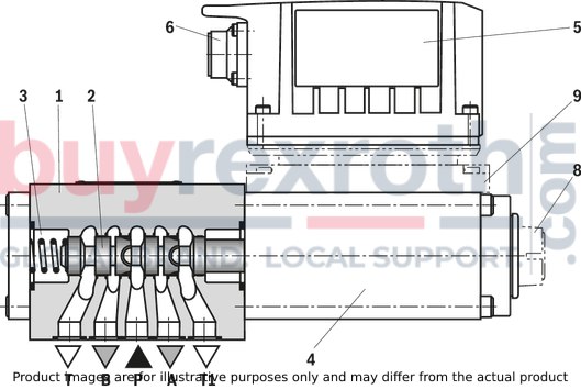
4/2 directional valve
The valve type 4WRPE is a direct operated directional control valve with electric position feedback and integrated electronics (OBE).
Set-up
The valve basically consists of:
Valve housing (1) Control spool (2) with compression springs (3) Control solenoid with position transducer (4) (optional with electronics protection membrane (8)) Integrated control electronics (OBE) (5) with analog interface (6) (optional with damping plate (9))
Function
The integrated electronics (OBE) compares the specified command value to the position actual value. In case of control deviations, the control solenoid will be activated. Due to the changed magnetic force, the control spool (2) is adjusted against the control spring. Stroke/control spool cross-section is controlled proportionally to the command value. With a positive command value presetting, the valve opens from P to B or A to T. Negative command values lead to no change in the control spool position.
Error detection
In the following cases of error, the electronics will de-energize the control solenoid:
Falling below the minimum supply voltage ≤ 15 V (restarting ≥ 17.5 V). Design “F1”: falling below the minimum current command value of 2 mA (comprises the cable break of the command value line (current loop).
Damping plate "D"
The damping plate (9) reduces the acceleration amplitudes on the on-board electronics (frequencies >300 Hz).
Notice:
Use of the damping plate is not recommended for applications with mainly low-frequency excitation <300 Hz.
Electronics protection membrane "-967"
To prevent condensate formation in the housing of the integrated electronics (OBE), an electronics protection membrane (8) can be used.
Recommended for use outside industry-standard conditions with high ambient air humidity and significant cyclic temperature changes (e. g. outdoors).
For applications outside these parameters, please consult us!
general
|
Type |
4WRPE | ||
|
Size |
10 | ||
|
Component series |
3X | ||
|
Design |
Directional spool valve, direct operated | ||
|
Type of actuation |
Proportional solenoid with position control, OBE | ||
|
Type of connection |
Subplate mounting, porting pattern according to ISO 4401-05-04-0-05 | ||
|
Installation position |
Any | ||
|
Mass |
4/3-way version |
kg |
7.6 |
|
4/2-way version |
kg |
6 | |
|
Ambient temperature range |
°C |
-20 … +60 | |
|
Storage temperature range with UV protection |
°C |
+10 … +40 | |
|
Transport temperature range |
°C |
-30 … +80 | |
|
Maximum storage time 1) |
yrs |
1 | |
|
Sine test according to DIN EN 60068-2-6 |
Without damping plate |
10 ... 2000 Hz / maximum 10 g / 10 cycles / 3 axes | |
|
With damping plate 2) |
10 ... 2000 Hz / maximum 10 g / 10 cycles / 3 axes | ||
|
Noise test according to DIN EN 60068-2-64 |
Without damping plate |
20 ... 2000 Hz / 10 gRMS / 30 g peak / 30 min / 3 axes | |
|
With damping plate 2) |
20 ... 2000 Hz / 10 gRMS / 30 gpeak/24 h/3 axes | ||
|
Transport shock according to DIN EN 60068-2-27 |
Without damping plate |
15 g / 11 ms / 3 shocks / 3 axes | |
|
With damping plate 2) |
15 g / 11 ms / 3 shocks / 3 axes | ||
|
Shock test according to DIN EN 60068-2-27 2) |
With damping plate |
35 g / 6 ms / 1000 shocks / 3 axes | |
|
Maximum relative humidity 3) |
% |
95 | |
|
Maximum solenoid surface temperature 4) |
°C |
150 | |
|
MTTFD values according to EN ISO 13849 5) |
Years |
150 | |
| 1) | If the storage conditions are observed; refer to the operating instructions 07600-B |
| 2) | Not recommended for applications with mainly low-frequency excitation < 300 Hz |
| 3) | No condensation |
| 4) | Individual operation |
| 5) | For further details, see data sheet 08012 |
hydraulic
|
Type |
4WRPE | ||
|
Size |
10 | ||
|
Maximum operating pressure |
Port P |
bar |
350 |
|
Port A |
bar |
350 | |
|
Port B |
bar |
350 | |
|
Port T |
bar |
200 | |
|
Hydraulic fluid |
see table "Hydraulic fluid" | ||
|
Hydraulic fluid temperature range 1) |
°C |
-20 … +70 | |
|
Viscosity range |
Maximum admissible |
mm²/s |
10 … 800 |
|
Recommended |
mm²/s |
20 … 100 | |
|
Maximum admissible degree of contamination of the hydraulic fluid, cleanliness class according to ISO 4406 (c) 2) |
Class 18/16/13 according to ISO 4406 (c) | ||
|
Hysteresis |
% |
< 0.25 | |
|
Response sensitivity |
% |
< 0.05 | |
|
Range of inversion |
% |
< 0.05 | |
|
Manufacturing tolerance |
% |
< 10 | |
|
Temperature drift 3) |
Zero shift < 0.2 % | ||
|
Pressure drift |
Zero shift < 0.2 % at 100 bar | ||
|
Zero point calibration (set in the plant) |
% |
± 1 | |
| 1) | flown-through |
| 2) | The cleanliness classes specified for the components must be adhered to in hydraulic systems. Effective filtration prevents faults and simultaneously increases the life cycle of the components. For the selection of the filters, see www.boschrexroth.com/filter. |
| 3) | Temperature range 20 °C ... 80 °C |
hydraulic
|
Nominal flow 1) |
l/min |
50 | 80 | |
|
Flow unloading central position |
Symbol W6; A – T |
l/min |
0.7 | |
|
Symbol W6; B – T |
l/min |
0.7 | ||
|
Symbol W8; A – T |
l/min |
- | 0.7 | |
|
Symbol W8; B – T |
l/min |
- | 0.7 | |
| 1) | With Δp = 5 bar/control edge; flow with deviating Δp see formula. |

|
Hydraulic fluid |
Classification |
Suitable sealing materials |
Standards |
Data sheet |
|
|
Mineral oils |
HL, HLP, HLPD, HVLP, HVLPD |
NBR, FKM |
DIN 51524 |
90220 |
|
|
Bio-degradable |
Insoluble in water |
HETG |
NBR, FKM |
ISO 15380 |
90221 |
|
HEES |
FKM |
||||
|
Soluble in water |
HEPG |
FKM |
ISO 15380 |
||
|
Containing water |
Water-free |
HFDU, HFDR |
FKM |
ISO 12922 |
90222 |
|
Containing water |
HFC (Fuchs Hydrotherm 46M, Petrofer Ultra Safe 620 ) |
NBR |
ISO 12922 |
90223 |
|
|
Important information on hydraulic fluids: For further information and data on the use of other hydraulic fluids, please refer to the data sheets above or contact us! There may be limitations regarding the technical valve data (temperature, pressure range, life cycle, maintenance intervals, etc.)! The ignition temperature of the hydraulic fluid used must be 40 K higher than the maximum solenoid surface temperature. Flame-resistant – containing water: Maximum operating pressure 210 bar Maximum pressure differential per control edge 175 bar Pressure pre-loading at the tank port >20 % of the pressure differential, otherwise increased cavitation erosion Life cycle as compared to operation with mineral oil HL, HLP 50 … 100 % Maximum hydraulic fluid temperature 50 °C |
|||||
electrical, integrated electronics (OBE)
|
Type |
4WRPE | ||
|
Size |
10 | ||
|
Power supply |
Nominal voltage |
VDC |
24 |
|
Terminal A |
VDC |
min. 19 / max. 36 | |
|
Terminal B |
VDC |
0 | |
|
Relative duty cycle 1) |
% |
100 | |
|
Fuse protection, external |
3.15 AT (time-lag) | ||
|
Input, version "A1" |
Differential amplifier, Ri = 100 kΩ | ||
|
Terminal D (UE) |
VDC |
0 … ±10 | |
|
Terminal E |
VDC |
0 | |
|
Input, version "F1" |
Load, Rsh = 200 Ω | ||
|
Terminal D (ID-E) |
mA |
4 … 20 | |
|
Terminal E (ID-E) |
Current loop ID-E return | ||
|
Maximum voltage for the differential inputs compared to 0 V |
D → B; E → B (max. 18 V) | ||
|
Test signal, version "A1" |
LVDT | ||
|
Terminal F (UTest) |
V |
0 … ±10 | |
|
Terminal C |
Reference 0 V | ||
|
Test signal, version "F1" |
LVDT signal 4 … 20 mA on external load 200 … 500 Ω maximum | ||
|
Terminal F (IF-C) |
mA |
4 … 20 | |
|
Terminal C (IF-C) |
Current loop IF-C return | ||
|
Maximum admissible residual ripple |
Vpp |
2.5 | |
|
Maximum power consumption |
VA |
65 | |
|
Functional earth and screening |
see pin assignment under "Electrical connection" (CE-compliant installation) | ||
|
Adjustment |
calibrated in the plant, see "characteristic curves" | ||
|
Protection class according to DIN EN 60529 |
IP65 with mounted and locked plug-in connectors | ||
|
Conformity |
CE according to EMC directive 2014/30/EU tested according EN 61000-6-2 and EN 61000-6-3 | ||
| 1) | Permanent light on/off |
Notice:
The specified technical data were measured with HLP46 and ϑOil = 40 ±5 °C.
(measured with HLP46, ϑoil = 40 ±5 °C)
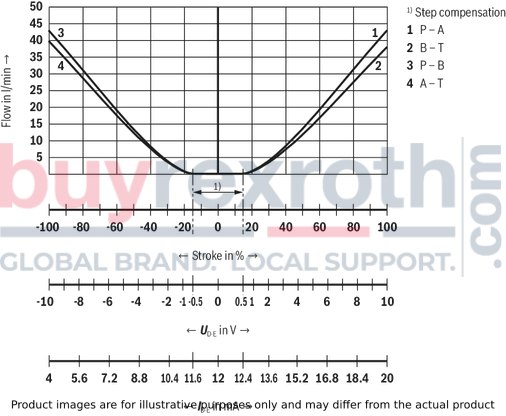
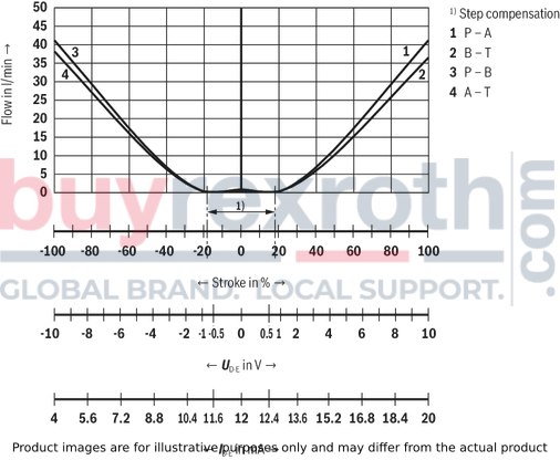
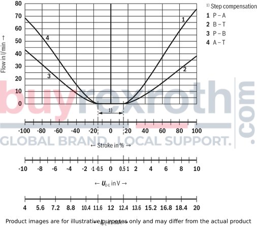
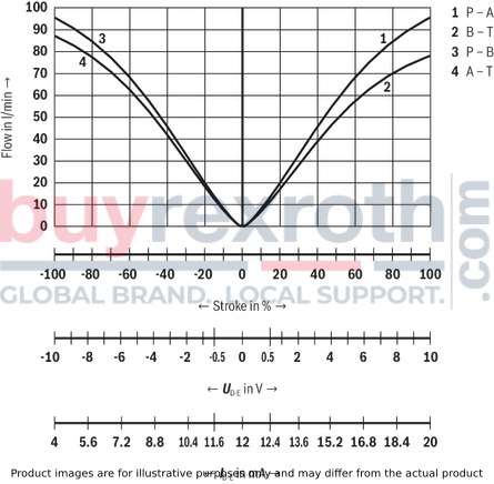
Flow/signal function (rated flow 50 l/min at Δp = 5 bar/control edge)
Symbol E
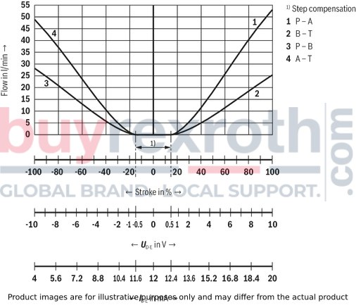
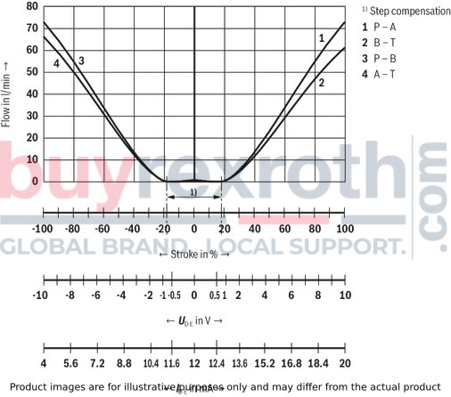
Flow/signal function (rated flow 50 l/min at Δp = 5 bar/control edge)
Symbol E1-
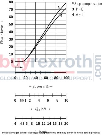
Flow/signal function (rated flow 50 l/min at Δp = 5 bar/control edge)
Symbol EA
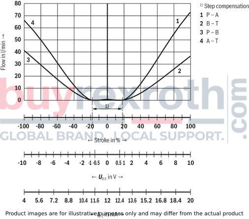
Flow/signal function (rated flow 50 l/min at Δp = 5 bar/control edge)
Symbol W6-
Flow/signal function (rated flow 50 l/min at Δp = 5 bar/control edge)
Symbol V
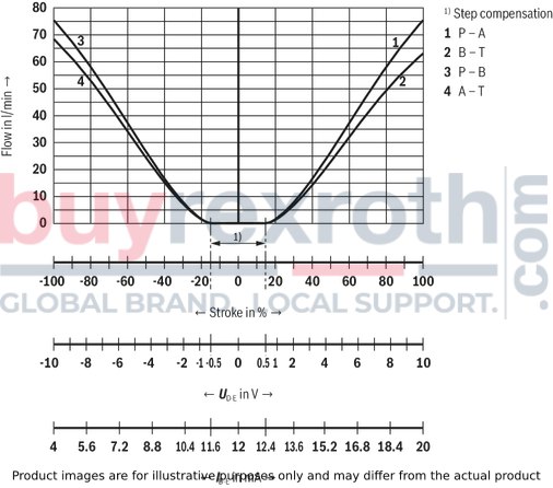
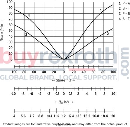
Flow/signal function (rated flow 80 l/min at Δp = 5 bar/control edge)
Symbol E
Flow/signal function (rated flow 80 l/min at Δp = 5 bar/control edge)
Symbol E1-
Flow/signal function (rated flow 80 l/min at Δp = 5 bar/control edge)
Symbol EA
Flow/signal function (rated flow 80 l/min at Δp = 5 bar/control edge)
Symbol W6-
Flow/signal function (rated flow 80 l/min at Δp = 5 bar/control edge)
Symbol W8-
Flow/signal function (rated flow 80 l/min at Δp = 5 bar/control edge)
Symbol V
Flow/signal function (rated flow 80 l/min at Δp = 5 bar/control edge)
Symbol V1-
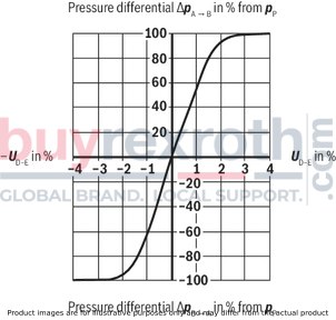
Pressure-signal characteristic curve
Symbol V
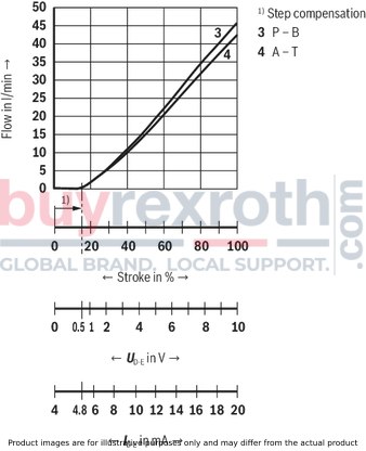
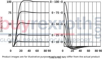
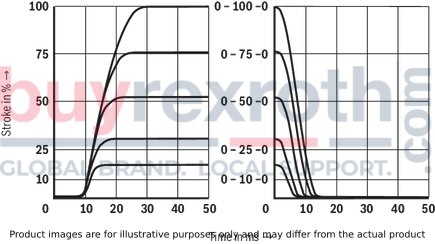
Transition function with stepped electric input signals (4/3 directional design)
Symbol V
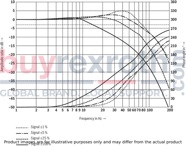
Frequency response
Symbol V
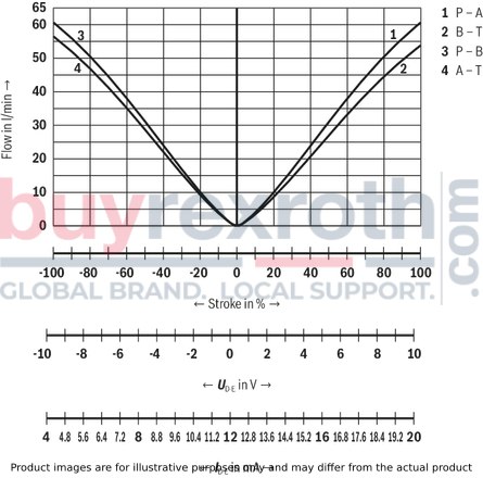
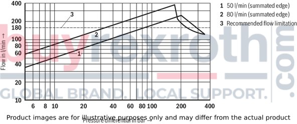
Flow/load function with maximum valve opening (tolerance ±10 %) (4/3 directional design)
Symbol V
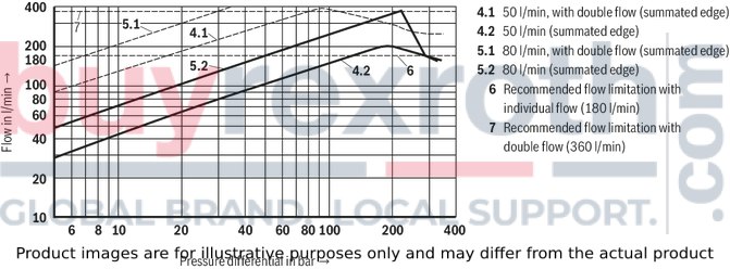
Flow/load function with maximum valve opening (tolerance ±10 %) (4/3 directional design)
Symbol EA
Transition function with stepped electric input signals (4/2 directional design)
Symbol EA
Symbols
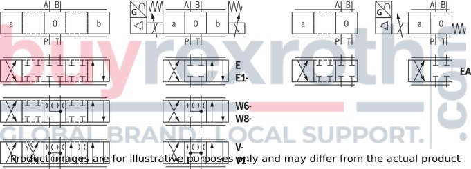
|
With symbol E1–, V1– and W8–: |
|
|
P → A: qv max |
B → T: qv/2 |
|
P → B: qv/2 |
A → T: qv max |
Notice:
Representation according to DIN ISO 1219-1.
Hydraulic interim positions are shown by dashes.
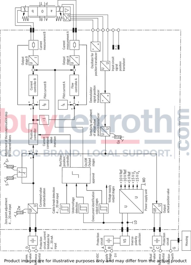
Block diagram / pin assignment (4/3 directional design)
Block diagram / pin assignment (4/2 directional design)
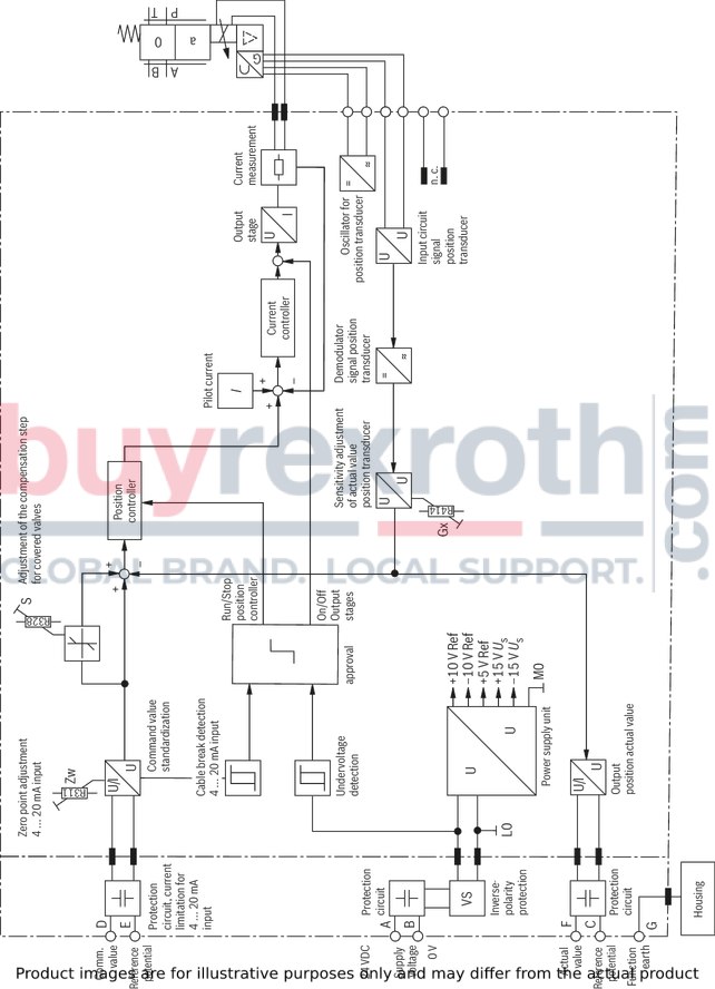
Notes:
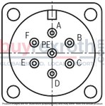
Electrical signals provided via control electronics (e.g. actual value) must not be used for switching off safety-relevant machine functions. The factory setting of the potentiometer must not be changed.|
Pin |
Signal |
Assignment interface "A1" |
Assignment interface "F1" |
|
A |
Power supply |
24 VDC |
|
|
B |
0 V |
||
|
C |
Reference (actual value) |
Reference potential actual value (pin F) |
|
|
D |
Differential amplifier input (command value) |
Command value ±10 mA |
Command value 4 … 20 mA |
|
E |
Reference potential command value (pin D) |
||
|
F |
Measuring output (actual value) |
Actual value ±10 V |
Actual value 4 … 20 mA |
|
PE |
Functional ground (directly connected to the valve housing) |
||
Command value:
Positive command value (0 ... 10 V or 12 ... 20 mA) at D and reference potential at E cause flow from P → A and B → T. Negative command value (0 ... -10 V or 12 ... 4 mA) at D and reference potential at E cause flow from P → B and A → T. With valves with solenoid on side a (symbol EA), a positive command value (0 ... 10 V or 4 ... 20 mA) at D and reference potential at E result in flow from P → B and A → T.
Connection cable (Recommendation):
Up to 20 m cable length type LiYCY 7 x 0.75 mm2 Up to 40 m cable length type LiYCY 7 x 1.0 mm2 EMC-compliant installation: Apply screening to both line ends Use metal mating connector (see "Accessories") Alternatively up to 30 m cable length admissible (not with version with damping plate) Apply screening on supply side Plastic mating connector (see "Accessories") can be used
Notice:
Mating connectors, separate order, see "Accessories" and data sheet 08006.
4/3-way version
Dimensions in mm

|
|
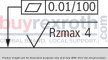
Required surface quality of the valve contact surface |
|
1 |
Name plate |
|
2 |
Valve housing |
|
3 |
Integrated electronics (OBE) |
|
4 |
Identical seal rings for ports A, B, P and T (T1) |
|
5 |
Control solenoid with position transducer |
|
6 |
Machined valve contact surface; Porting pattern according to ISO 4401-05-04-0-05 |
|
7 |
Stroke solenoid |
|
8 |
ISA adapter, separate order, see data sheet 08006 |
|
9 |
Damping plate "D" |
|
10 |
Dimension in () for version with damping plate "D" |
|
11 |
Electronics protection membrane "-967" |
4/2-way version
Dimensions in mm

|
|
|
Required surface quality of the valve contact surface |
|
1 |
Name plate |
|
2 |
Valve housing |
|
3 |
Integrated electronics (OBE) |
|
4 |
Identical seal rings for ports A, B, P and T (T1) |
|
5 |
Control solenoid with position transducer |
|
6 |
Machined valve contact surface; Porting pattern according to ISO 4401-05-04-0-05 |
|
9 |
Damping plate "D" |
|
10 |
Dimension in () for version with damping plate "D" |
|
11 |
Electronics protection membrane "-967" |
|
Quantity |
Hexagon socket head cap screws |
Material number |
|
4 |
ISO 4762 - M6 x 40 - 10.9-CM-Fe-ZnNi-5-Cn-T0-H-B (Friction coefficient μtotal = 0.09 … 0.14) Tightening torque MA = 12.5 Nm ±10 % |
R913051533 |
|
or |
||
|
4 |
ISO 4762 - M6 x 40 - 10.9 Tightening torque MA = 15.5 Nm ±10 % |
Not included in the Rexroth delivery range |
Notes:
The tightening torque of the hexagon socket head cap screws refers to the maximum operating pressure. The dimensions are nominal dimensions which are subject to tolerances. Mating connectors, separate order, see "Accessories" and data sheet 08006.Service case with test unit for proportional servo valves with integrated electronics (OBE)
VT-VETSY-1-1X
Service case with test unit for proportional servo valves with integrated electronics (OBE)
VT-VETSY-1-1X
Component series 1XData sheet
Configurator / CAD
Spare parts & repair
Mating connectors for valves with round connector, 6-pole + PE
7P Z31

Mating connectors for valves with round connector, 6-pole + PE
7P Z31
For valves with round connector according to EN 175201-804, 6-pole + PE as well as 6-pole, compatible with VG 95328Data sheet
Spare parts & repair
Mating connectors for valves with round connector, 6-pole + PE, shielded, with assembled connection line
7P Z31 +
Mating connectors for valves with round connector, 6-pole + PE, shielded, with assembled connection line
7P Z31 +
For valves with round connector according to EN 175201-804, 6-pole + PE as well as 6-pole, compatible with VG 95328Data sheet
Spare parts & repair
Related Products
R901401274
$5,685.00 USD
R901396516
$5,399.00 USD
R901396518
$5,399.00 USD
R901401546
$5,870.00 USD
R901392640
$5,399.00 USD


