FESE63CA-3X/1800LK0G1V
Manufacturer: Bosch Rexroth
Material #: R901276354
Model : FESE63CA-3X/1800LK0G1V
***Disclaimer: The following summary contains information gathered from various sources such as product descriptions, technical specifications and catalogs. While efforts have been made to provide accurate details, inaccuracies may occur. It is advised to verify all information by contacting Bosch Rexroth directly.***
The Bosch Rexroth FESE63CA-3X/1800LK0G1V (R901276354) is a sophisticated pilot-operated way proportional throttle valve designed for block installation, offering precise flow control in hydraulic systems. This valve is engineered to regulate flow continuously by controlling the position of its orifice spool through command value-dependent feedback. The FESE63CA-3X/1800LK0G1V features integrated electronics with a position transducer that ensures accurate spool positioning by comparing actual and command values, making real-time adjustments via the proportional solenoid.
The valve's construction includes a cover with pilot oil connections, a main valve with an orifice spool, a pilot control valve with a proportional solenoid, and integrated electronics. Its area ratio allows for efficient flow control in various sizes (NG6 to NG25), and it offers the flexibility of external pilot oil supply via port X. In case of an enable signal disconnect, the orifice spool moves to block the flow direction from A to B without leakage.
This model is capable of operating in both flow directions A to B and B to A, ensuring versatility in application. It can be paired with a pressure compensator for load-compensated flow control, enhancing its capability in closed-loop systems. The unit comes fully adjusted with onboard electronics (OBE), and it offers options for voltage or current interface connections.
In terms of safety features, Bosch Rexroth has incorporated fail-safe measures that de-energize the solenoid during supply voltage failure or cable breakage in the position transducer, causing the spool to block the flow automatically. However, users should note that sudden stoppage due to voltage failure may result in machine damage due to acceleration forces.
Designed according to DIN ISO standards for installation dimensions, this model boasts maximum operating pressures up to 350 bar and is available in various sizes denoted by its component series X designation.
$27,905.00 USD
More are expected on May 16, 2025
Status: This product is temporarily out of stock.
Qty: Delivered as early as May 16, 2025 when ordered in
This product is eligible for factory repair.
Pilot-operated 2-way proportional throttle valve in block installation technology Installation dimensions according to DIN ISO 7368 Orifice spool electrically position-controlled Flow in both directions In case of power failure, cable break or disconnection of enable, the orifice spool will automatically move into seat position and block the flow in both directions Can be used for pressure-compensated closed-loop flow control in conjunction with a pressure compensator Completely adjusted unit with integrated electronics (OBE), optionally available with voltage or current interface
Valves of type FESE are pilot-operated 2-way proportional throttle valves for block installation for the continuous control of flows.
Technical set-up:
The valve consists of four main assemblies:
Cover (1) with connection surface for pilot oil connections Main valve (2) with orifice spool (3) Pilot control valve (4) with proportional solenoid (5) Integrated electronics (6) with position transducer (7)General function:
Command value-dependent position control of the orifice spool (3) and thus defined opening of the orifice (8). The flow depends on the Δp across the orifice (8) and the position of the orifice spool (3). Actual value recording of the orifice spool (3) position by the position transducer (7); command/actual value comparison in the electronics (6); variations are prepared and forwarded as control output for correction of the orifice spool (3) position to the proportional solenoid (5) to the pilot control valve (4). Area ratio of area (14) to area (15) = 2 : 1 for NG25; 32; 40 and 1.6 : 1 for NG50; 63. Flow direction A → B (connect X to A); Flow direction B → A (connect X to B); External pilot oil supply possible via X. When the enable is disconnected, the orifice spool (3) will move onto the valve seat (9) and block the flow direction A → B in a leakage oil-free manner. The spool seal (11) seals port B to the control chamber (12) in a leakage oil-free manner; with internal pilot oil supply observe leakage oil from X via the pilot control valve to Y! Orifice spool position at command value 0 V or 4 mA already regulated, whereas the orifice (8) is still located in the positive overlap.Open orifice spool function:
(Assumption flow A → B and A connected to X)
The proportional solenoid (5) moves the pilot spool (4.1) against the spring (13) and opens the connection from control chamber (12) to Y; pressure reduction in the control chamber (12) and movement of orifice spool (3) in opening direction by the pressure in A on the area (15) plus the pressure n B on the annulus area (16).Close orifice spool function:
(Assumption flow A → B and A connected to X)
Flow reduction in the proportional solenoid (5); the spring (13) moves the pilot spool (4.1) against the proportional solenoid and opens the connection from X to the control chamber (12); pressure build-up in the control chamber (12); pressure on the areas (14) plus spring force (10) move the orifice spool (3) in closing directionFlow control function:
Can be used in connection with a pressure compensator for the load-compensated control of a flowSupply voltage failure:
The integrated electronics de-energize the solenoid in case of supply voltage failure or cable break in the position transducer (7) The pressure applied to control port X plus the spring force (10) move the spool onto the valve seat (9) where it blocks the flow A → B.Notice;
Failure of the supply voltage will lead to an abrupt standstill of the control axis. The acceleration forces occurring in this connection may cause machine damage!
Type FESE..CA-3X/...
01 |
02 |
03 |
04 |
05 |
06 |
07 |
08 |
09 |
10 |
||
FESE |
C |
A |
- |
3X |
/ |
K0 |
* |
01 |
Electrically operated 2-way proportional throttle valve for block installation |
FESE |
02 |
Size 25 |
25 |
Size 32 |
32 |
|
Size 40 |
40 |
|
Size 50 |
50 |
|
Size 63 |
63 |
|
03 |
Installation kit |
C |
Flow direction |
||
04 |
A to B (X connected to A) B to A (X connected to B) |
A |
05 |
Component series 30 ... 39 (30 ... 39: unchanged installation and connection dimensions) |
3X |
Flow characteristic linear |
||
06 |
NG25 |
|
Up to 315 l/min |
315L 1) |
|
NG32 |
||
Up to 450 l/min |
450L 1) |
|
NG40 |
||
Up to 670 l/min |
670L 1) |
|
NG50 |
||
Up to 1400 l/min |
1400L 1) |
|
NG63 |
||
Up to 1800 l/min |
1800L 1) |
|
Electrical connection |
||
07 |
Without mating connector, with connector according to DIN 43651, separate order |
K0 |
Electrical interface |
||
08 |
Command value input 0 to 10 V / actual value output 0 to -10 V |
B1 |
Command value input 4 to 20 mA / actual value output 4 to 20 mA |
G1 |
|
Seal material |
||
09 |
NBR seals, suitable for mineral oil HL and HLP according to DIN 51524 |
M |
FKM seals |
V |
|
10 |
Further details in the plain text |
* |
1) |
Rated flowat 10 bar valve pressure differential between port A and B |
For applications outside these parameters, please consult us!
general
Type |
FESE | |
Size |
63 | |
Component series |
3X | |
Installation position |
Any | |
Weight |
kg |
21.2 |
Storage temperature range |
°C |
-20 … +80 |
Ambient temperature range |
°C |
-20 … +50 |
hydraulic
Type |
FESE | ||
Size |
63 | ||
Maximum operating pressure |
bar |
315 | |
Maximum operating pressure |
Port A |
bar |
315 |
Port B |
bar |
315 | |
Maximum pilot pressure |
Port X |
bar |
315 |
Return flow pressure |
Port Y |
depressurized to the tank | |
Minimum inlet pressure |
in port A (flow direction A → B) |
bar |
20 |
in port B (flow direction B → A) |
bar |
25 | |
Pilot oil volume for switching process seat position |
0 → 100 % |
cm³ |
52 |
Maximum pilot oil flow |
Port Y |
l/min |
17 |
Flow direction |
Internal pilot oil supply A → B |
Connect A to X | |
Internal pilot oil supply B → A |
Connect B to X | ||
External pilot oil supply A → B |
Pressure at X > pressure in A | ||
External pilot oil supply B → A |
Pressure at X > pressure in B | ||
Zero flow |
State: Enable inactive (solenoid de-energized) |
A → B / B → A locked in a leak-free manner | |
State: Command value 0 V or 4 mA from A → B / B → A |
See characteristic curves | ||
State: Command value 0 V or 4 mA from A → X / B → X |
l/min |
< 0.3 | |
Hydraulic fluid temperature range |
°C |
-20 … +80 | |
Viscosity range |
mm²/s |
15 … 380 | |
Maximum admissible degree of contamination of the hydraulic fluid, cleanliness class according to ISO 4406 (c) 1) |
Pilot control valve |
Class 17/15/12 according to ISO 4406 (c) | |
Main valve |
Class 20/18/15 according to ISO 4406 (c) | ||
Hysteresis |
% |
< 0.2 | |
Response sensitivity |
% |
< 0.1 | |
Range of inversion |
% |
< 0.15 |
1) | The cleanliness classes specified for the components must be adhered to in hydraulic systems. Effective filtration prevents faults and simultaneously increases the life cycle of the components. For the selection of the filters, see www.boschrexroth.com/filter. |
Hydraulic fluid |
Classification |
Suitable sealing materials |
Standards |
Mineral oils and related hydrocarbons |
HL, HLP |
NBR / FKM |
DIN 51524 |
For more information and data on the use of other hydraulic fluids please contact us. |
electrical
Type |
FESE | ||
Voltage type |
Direct voltage | ||
Duty cycle |
% |
100 | |
Current consumption |
Imax |
A |
1.3 |
Impulse load |
A |
1.5 | |
Protection class according to DIN EN 60529 |
IP65 (with mating connector mounted and locked) |
electrical, inductive position transducer
Type |
FESE | ||
Coil resistance at 20°C |
Total resistance between 1 and 2 |
Ω |
31.5 |
Total resistance between 2 and PE |
Ω |
45.5 | |
Total resistance between PE and 1 |
Ω |
31.5 | |
Type of protection according to EN 60529 |
IP65 (with mating connector mounted and locked) | ||
Inductivity |
mH |
6 ... 8 | |
Oscillator frequency |
kHz |
2.5 | |
Electrical position measurement system |
Differential throttle |
FES(E) 63 C.../1800L... flow direction A → B
FES(E) 63 C.../1800L... flow direction B → A
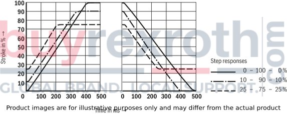
Transition function with stepped electric input signals
NG50
1) | Measuring conditions: pressure in A = 50 bar; actuator in B closed (pA = pB = 50 bar); pressure in A < 50 bar → actuating time increases; pressure in A > 50 bar → actuating time decreases; changes in the actuating time are influenced by the area ratio of the orifice spool as follows:→ command value 0 → 100 %: The actuating time decreases the higher the inlet pressure and the smaller the Δp across the valve is. → Command value 100 → 0 %: The actuating time decreases the higher the inlet pressure and the larger the Δp across the valve is. |
Zero flow from A → B and B → A dependent on the pressure differential Δp (command value 0 V and/or 4 mA)
NG63
simplified |
Type FESE..CA-3X/... |
A working port B working port X pilot oil supply Y pilot oil return |
Flow direction A to B (X connected to A)Flow direction B to A (X connected to B) |
Pin assignment |
Contact |
Signal with B1 interface |
Signal with G1 interface |
Operating voltage +UL |
1 |
UB = 24 VDC (uB(t) = 21,6 ... 36 V) |
|
Ground L0 |
2 |
||
Enable input / reference for pin 2 |
3 |
log1 = 10 V ... 36 V; log0 = U < 8 V |
|
Command value input |
4 |
0 V ... 10 V (Re > 50 kΩ) |
4 to 20 mA; load resistance maximum 100 Ω |
Command value input, reference |
5 |
||
Actual value output |
6 |
0 V ... -10 V (Imax = 5 mA) |
4 ... 20 mA; load resistance maximum 500 Ω |
Actual value output, reference |
7 |
||
not assigned |
8 |
||
not assigned |
9 |
||
not assigned |
10 |
||
Ready for operation (output) |
11 |
Valve not ready for operation: UPin11 < 8 V;Valve ready for operation: UPin11 = UB - 3 V;Reference - Pin 2: (Imax against 0 V; 50 mA); |
|
Protective earthing conductor |
PE |
||
Recommendation connection cable |
...25m → 0,75 mm² ...50 m → 1,5 mm² |
Function
1. Switch-on procedure/Fault behavior:
After applying the supply voltage of 24 V, the electronics are ready for operation provided that the following conditions are met:
The operating voltage UB > 18 VDC The internal supply voltage ± 7.5 V is symmetric The connection to the position transducer is not interrupted. The command value line is not interrupted (only with 4 mA ... 20 mA interface)If one of the conditions is not satisfied, the controller and the output stage are blocked and the ready for operation signal is set to < 8 V.
2. Normal operation
With inactive enable (< 8 V) and any command value presetting (0 ... 10 V or 4 ... 20 mA), the orifice spool rests against the stop and blocks the flow from A to B.
By applying a voltage > 10 V at the enable, the position controller for the orifice spool and the output stage for the pilot control valve are activated. Simultaneously, the actual value from the orifice spool position is compared to the applied command value in the position controller (PID) and a control output is sent to the output stage which changes the solenoid current until the orifice spool position corresponds to the command value.
The actual value of the orifice spool position is recorded by an inductive position transducer. Its signal is rectified by the demodulator and fed back to the PID controller.
The following are available as output signals at the connector:
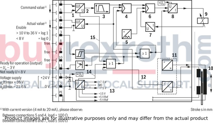
Actual position value FESE.../...B1 (pin 6) 0 V ... –10 V corresponds to 0 % ... 100 % valve opening Orifice spool in seat position → actual value > 0.8 V Actual position value FESE.../...G1 (pin 6) 4 mA ... 20 mA corresponds to 0 % ... 100 % valve opening Orifice spool in seat position → actual value < 2.7 mA Ready for operation signal (pin 11) all conditions specified above are satisfied → > 10 V one of the conditions is not satisfied → < 8 VBlock diagram / pin assignment
1 |
Inlet |
2 |
Outlet |
3 |
Fixed ramp |
4 |
Position controller |
5 |
Clock |
6 |
Current controller |
7 |
I/U transformer |
8 |
Output stage |
9 |
Proportional solenoid |
10 |
Position transducer |
11 |
Oscillator/demodulator |
12 |
Error signal position transducer |
13 |
Power supply unit |
14 |
Error signal in case of +UB undervoltage and imbalance in the power supply unit |
15 |
Cable break signal at current command value |
Mating connector according to DIN 43651/11-pole + PE/Pg16
separate order under material no. R900884671 (plastic version)
Assembly consisting of items 1 and 1.1 or items 1 and 1.2, protection class IP65
Notice:
If one cable is used, combine item 1 with item 1.1 If two cables are used, combine item 1 with item 1.2Dimensions in mm
Unit dimensions
NG |
25 |
32 |
40 |
50 |
63 |
H11 |
51 |
63 |
62 |
73 |
90 |
H12 |
116 |
128 |
127 |
138 |
155 |
H13 |
110 |
122 |
121 |
132 |
149 |
H16 |
279 |
291 |
290 |
301 |
318 |
H17 |
25 |
35 |
45 |
45 |
65 |
L1 |
85 |
102,5 |
126 |
140 |
180 |
L2 |
93,5 |
102,5 |
126 |
140 |
180 |
L3 |
42,5 |
51,25 |
63 |
70 |
90 |
L7 |
38,5 |
51,25 |
63 |
66 |
86 |
L8 |
139 |
150 |
169 |
184 |
219 |
L9 |
15 |
15 |
15 |
15 |
15 |
L10 |
10 |
18,75 |
30,5 |
37,5 |
57,5 |
1 |
Name plate |
2 |
Identical seal rings for ports X and Y |
3 |
4 valve mounting screws according to ISO 4762 - 10.9 (included in the scope of delivery):NG25: M12 x 60, tightening torque MA = 75 Nm |
4 |
Mating connector according to DIN 43651/11-pole + PE/Pg16, separate order |
6 |
Space required to remove the mating connector |
7 |
Port X |
8 |
Port Y |
9 |
Locating hole |
10 |
Depth of fit |
11 |
Control dimension |
12 |
Port B may be positioned around the central axis of port A. However, it must be observed that the mounting bores and the control bores are not damaged. |
13 |
If a different diameter is used for port B than indicated, the distance from the cover support surface to the bore center must be calculated. |
Installation dimensions according to DIN ISO 7368 |
|||||
NG |
25 |
32 |
40 |
50 |
63 |
ØD1H8 |
45 |
60 |
75 |
90 |
120 |
ØD2 |
25 |
32 |
40 |
50 |
63 |
ØD3 |
25 |
32 |
40 |
50 |
63 |
ØD3 max. |
32 |
40 |
50 |
63 |
80 |
ØD4H8 |
34 |
45 |
55 |
68 |
90 |
D5 |
M12 |
M16 |
M20 |
M20 |
M30 |
ØD6 max. |
6 |
8 |
10 |
10 |
12 |
ØD7H13 |
6 |
6 |
6 |
8 |
8 |
H1 |
44 |
52 |
64 |
72 |
95 |
H1 1) |
40,5 |
48 |
59 |
65,5 |
86,5 |
H2 |
72 |
85 |
105 |
122 |
155 |
H3 |
58 |
70 |
87 |
100 |
130 |
H4 |
25 |
35 |
45 |
45 |
65 |
H5 |
12 |
13 |
15 |
17 |
20 |
H6 |
2,5 |
2,5 |
3 |
3 |
4 |
H7 |
30 |
30 |
30 |
35 |
40 |
H8 |
2,5 |
2,5 |
3 |
4 |
4 |
H9 min. |
1 |
1,5 |
2,5 |
2,5 |
3 |
H10 min. |
8 |
8 |
8 |
8 |
8 |
L1 |
85 |
102,5 |
126 |
140 |
180 |
L2 |
93,5 |
102,5 |
126 |
140 |
180 |
L3 |
42,5 |
51,25 |
63 |
70 |
90 |
L4 |
58 |
70 |
85 |
100 |
125 |
L5 |
33 |
41 |
50 |
58 |
75 |
L6 |
16 |
17 |
23 |
30 |
38 |
L7 |
29 |
35 |
42,5 |
50 |
62,5 |
1) |
Bore center with ØD3 max. |
Mating connectors for valves with connector “K4”, without circuitry, standard
3P Z4
Mating connectors for valves with connector “K4”, without circuitry, standard
3P Z4
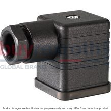
For valves with connector “K4” according to EN 175301-803 and ISO 4400, 2-pole + PE, “large cubic connector” Mating connectors for valves with one or two solenoids (individual connection)Data sheet
Spare parts & repair
Mating connectors for valves with round connector, 11-pole + PE
12P N11
Mating connectors for valves with round connector, 11-pole + PE
12P N11
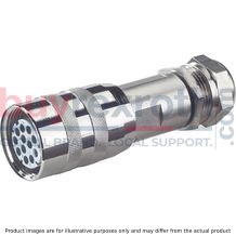
For valves with round connector according to EN 175201-804, 11-pole + PEData sheet
Spare parts & repair
Mating connectors for valves with round connector, 11-pole + PE, shielded, with assembled connection line
12P N11 +
Mating connectors for valves with round connector, 11-pole + PE, shielded, with assembled connection line
12P N11 +
For valves with round connector according to EN 175201-804, 11-pole + PEData sheet
Spare parts & repair
Related Products
R901218887
$9,671.00 USD
R900962529
$6,478.00 USD
R901304402
$2,355.00 USD
R900955075
$6,521.00 USD
R900954269
$9,222.00 USD