INTERNAL GEAR PUMP PGH5-3X/125RE11VE4
Manufacturer: Bosch Rexroth
Material #: R901147125
Model : PGH5-3X/125RE11VE4
***Disclaimer: The following summary contains information gathered from various sources such as product descriptions, technical specifications and catalogs. While efforts have been made to provide accurate details, inaccuracies may occur. It is advised to verify all information by contacting Bosch Rexroth directly.***
The Bosch Rexroth PGH5-3X/125RE11VE4 (R901147125) is an internal gear pump designed for high-efficiency industrial applications within an open control loop. This pump features a cast iron housing and FKM seals, ensuring durability and compatibility with hydraulic fluids such as HLP, HEES, and HFDU. With a maximum pressure of 315 bar and a displacement type that is constant, the PGH5-3X/125RE11VE4 offers reliable performance with low noise levels and reduced pulsation.
The model is optimized for variable speed drives, allowing for flexible operation across different conditions without load cycle limitation. The cylindrical shaft end measures mm with a fitting key compliant with ISO standards. Additionally, it has a fastening hole mounting flange BSW according to ISO norms.
This particular pump has a minimum speed requirement and can achieve a maximum flow rate at its peak rotational speed. It's designed to rotate clockwise and supports throughdrive options. The weight of the unit ensures stability in operation.
With its gap-compensated design, this Bosch Rexroth internal gear pump maintains high volumetric efficiency throughout its lifespan due to automatic clearance adjustment facilitated by radial compensation elements. These elements consist of segments, segment supports, and seal rolls that ensure separation of suction and pressure ranges while providing sealing with minimal mechanical loss.
The PGH5-3X/125RE11VE4's hydrodynamic and hydrostatic mountings contribute to its low operating noise and flow pulsation characteristics, making it suitable for applications requiring fatigue-resistant drives with high power demands such as plastics processing machines, presses that can be automated, casting machines, and accumulator charging operations. It's compatible with other pumps like axial piston pumps or vane pumps for versatile system integration.
Overall, the Bosch Rexroth PGH5-3X/125RE11VE4 stands out for its robust construction, consistent performance under varying conditions, and seamless integration into various industrial systems demanding high-pressure capabilities.
$8,798.00 USD
More are expected on September 3, 2026
Status: This product is temporarily out of stock.
Qty: Delivered as early as September 3, 2026 when ordered in
This product is eligible for factory repair.
Internal gear pump, size 125, pressure 350 bar for industrial applications, open circuit
Optimized for variable-speed drives. Low noise and low pulsation level. High efficiency. No load cycle limitation
Unpacked Weight: 47.361 kg
Set-up
Hydraulic pumps of type PGH.-3X are gap-compensated internal gear pumps with constant displacement.
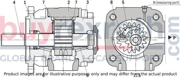
They basically comprise of: Mounting flange (1), housing (2), cover with through-drive (3), pinion shaft (4), internal gear (5), plain bearings (6), axial washers (7) and stop pin (8) as well as the radial compensation consisting of segment (9), segment support (10) and the seal rolls (11).
Suction and displacement procedure
The hydrodynamically mounted pinion shaft (4) drives the internally geared internal gear (5) in the direction of rotation shown.
The tooth clearances opening in the suction range suck in the fluid. The fluid is transported into the tooth clearances of pinion and internal gear, from the suction range (S) into the pressure range (P).
There, the fluid is displaced from the closing tooth clearances and delivered into the pressure port (P).
Suction and pressure range are separated by the radial compensation elements (9 to 11) and the tooth engagement between internal gear and pinion shaft.
Axial compensation
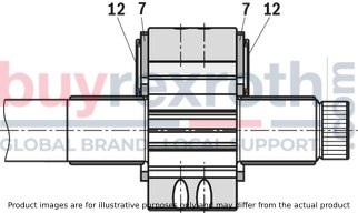
The displacement area in the pressure range is axially sealed by axial washers (7).
To the sides of the axial washers facing away from the displacement area a pressure field (12) is applied. These fields balance the axial washers vis-à-vis the displacement area, which results in a perfect sealing with low mechanical losses.
Radial compensation
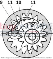
The radial compensation elements consist of segment (9), segment support (10) and seal rolls (11).
Segment (9) and segment support (10) are arranged in the pressure field so that the resulting compressive force is basically accepted by the stop pin.
A small compressive force component presses segment and segment support onto the tooth tips of pinion shaft and internal gear and in this way provides for the sealing of the pressure range to the suction range with automatic clearance adjustment.
This is the prerequisite for constantly high volumetric efficiency during the entire operating time.
The clearance adjustment of segment and segment support is made possible by the seal rolls located inbetween.
Hydrodynamic and hydrostatic mounting
The pinion shaft (4) is accepted by hydrodynamically lubricated radial plain bearings (6).
The internal gear (5) is mounted hydrostatically in the housing.
Gear tooth system
The gear tooth system with involute edges has a large meshing length for little flow and pressure pulsation and thus guarantees low-noise running.
PGH-type hydraulic pumps are gap-compensated internal gear pumps with fixed displacement. The hydrodynamically mounted pinion shaft drives the internal gear. The pinion shaft and internal gear tooth clearances opening in the suction range suck in the hydraulic fluid and transport it to the pressure range. The suction and pressure range are separated by the radial compensation elements and the tooth engagement between the internal gear and pinion shaft.
| Data Sheet | Download Data Sheet |
| 3D CAD | Download 3D CAD |
| 3D CAD | Download 3D CAD |
| Manual | Download Manual |
| Manual | Download Manual |
| Manual | Download Manual |
| Manual | Download Manual |
| Manual | Download Manual |
| Displacement type | constant |
| Size | 125 |
| Max. pressure | 350 |
| Max. flow | 375 |
| Shaft end | Cylindrical Ø 40 with fitting key, ISO 3019-2 |
| Through-drive | with |
| Direction of rotation | clockwise rotation |
| Shaft end | Cylindrical Ø 40 mm with fitting key, ISO 3019-2 |
| Fastening | 4-hole mounting flange 160B4SW according to ISO 3019-2 |
| Hydraulic fluid | HLP,HEES,HFDU |
| Seals | FKM shaft seal ring and FKM seals |
| Fastening | 4-hole mounting flange 160B4SW, ISO 3019-2 |
| Speed min. | 200 |
| Productgroup ID | 9,10,11,12,13,14 |
| Speed max. | 3000 |
| Weight | 47.361 |
Fixed displacement Low operating noise Low flow pulsation High efficiency also at low speed and viscosity due to sealing gap compensation Suitable for broad viscosity and speed ranges All frame sizes and sizes can be combined with each other Can be combined with axial piston pumps, internal gear pumps and vane pumps Suitable for operation with HFC fluid (seal design “W”) Use:
For fatigue-resistant drives with high power and high pressures with very large numbers of load cycles, e.g. plastics processing machines, automatable presses, casting machines and other applications with accumulator charging operation
Single pumps
|
01 |
02 |
03 |
04 |
05 |
06 |
07 |
08 |
09 |
10 |
11 |
||
|
PG |
H |
– |
3X |
/ |
* |
|
01 |
Internal gear pump, fixed displacement, gap-compensated |
PG |
||
|
Series |
||||
|
02 |
High-pressure pump |
H |
||
|
Frame size |
||||
|
03 |
BG4 |
4 |
||
|
BG5 |
5 |
|||
|
04 |
Component series: Component series 30 to 39 (30 to 39: unchanged installation and connection dimensions) |
3X |
||
|
Size |
||||
|
05 |
BG4 |
NG |
Displacement/rotation |
|
|
20 |
20,10 cm3 |
020 |
||
|
25 |
25,30 cm3 |
025 |
||
|
32 |
32,70 cm3 |
032 |
||
|
40 |
40,10 cm3 |
040 |
||
|
50 |
50,70 cm3 |
050 |
||
|
BG5 |
63 |
64,70 cm3 |
063 |
|
|
80 |
81,40 cm3 |
080 |
||
|
100 |
100,20 cm3 |
100 |
||
|
125 |
125,30 cm3 |
125 |
||
|
160 |
162,80 cm3 |
160 |
||
|
200 |
200,40 cm3 |
200 |
||
|
250 |
250,50 cm3 |
250 |
||
|
Direction of rotation (looking at the shaft end) |
||||
|
06 |
Clockwise |
R |
||
|
Counterclockwise rotation (upon request) |
L |
|||
|
Shaft design |
||||
|
07 |
Cylindrical |
E |
||
|
SAE involute gear |
R |
|||
|
Line connection 3) |
||||
|
08 |
SAE flange standard pressure series |
07 |
||
|
SAE flange high-pressure series |
11 |
|||
|
Seal material |
||||
|
09 |
FKM seals |
V |
||
|
Shaft seal ring made of NBR (other seals made of FKM) |
W 2) |
|||
|
Type of connection |
||||
|
10 |
SAE 2-hole mounting flange |
U2 |
||
|
ISO 4-hole mounting flange according to ISO 3019-2 and VDMA 24560 |
E4 1) |
|||
|
11 |
Further details in the plain text |
* |
||
| 1) | only in connection with cylindrical shaft (according to VDMA), only with clockwise rotation |
| 2) | in case of operation with HFC fluid |
| 3) |
for every size, one type of connection 07 or 11 has been defined: 07: PGH5-3X/200/250… 11: PGH4-3X/020/025/032/040/050… PGH5-3X/063/080/100/125/160... |
Not all variants according to the type key are possible! Please select the desired pump using the selection tables (see Dimensions) or after consultation with Bosch Rexroth.
The suction ports have all been designed in standard pressure series (dimensions see Dimensions).
|
Preferred types PGH4-3X |
|
|
Type |
Part number |
|
PGH4-3X/020RE11VU2 |
R901147100 |
|
PGH4-3X/025RE11VU2 |
R901147101 |
|
PGH4-3X/032RE11VU2 |
R901147102 |
|
PGH4-3X/040RE11VU2 |
R901147103 |
|
PGH4-3X/050RE11VU2 |
R901147104 |
|
Preferred types PGH5-3X |
|
|
Type |
Part number |
|
PGH5-3X/063RE11VU2 |
R901147115 |
|
PGH5-3X/080RE11VU2 |
R901147116 |
|
PGH5-3X/100RE11VU2 |
R901147117 |
|
PGH5-3X/125RE11VU2 |
R901147118 |
|
PGH5-3X/160RE11VU2 |
R901147119 |
|
PGH5-3X/200RE07VU2 |
R901147120 |
|
PGH5-3X/250RE07VU2 |
R901147121 |
All internal gear pumps of type PGH-3 can be combined, every pump is equipped with an output shaft gear tooth system. The combination possibilities and die material numbers of the required combination parts are available in the following table.
Please observe the project planning information for pump combinations.
|
Back pump |
Front pump |
|
|
Part number |
||
|
PGH4-3X |
PGH5-3X |
|
|
PGH2-2X/...R...U2 (RD10223) |
R901155288 |
R901155283 |
|
PGH3-2X/...R...U2 (RD10223) |
R901155288 |
R901155283 |
|
PGH4-3X/...R...U2 |
R901155289 |
R901155284 |
|
PGH5-3X/...R...U2 |
– |
R901155285 |
|
PGF2-2X/...J...U2 (RD10213) |
R901155288 |
R901155283 |
|
PGP2-2X/...J...U2 (RD10231) |
R901155288 |
R901155283 |
|
PGF3-3X/...J...U2 (RD10213) |
R901155287 |
R901155282 |
|
PGP3-3X/...J...U2 (RD10231) |
R901155287 |
R901155282 |
|
PVV/Q1-1X/...J…B (RD10335) |
R901155287 |
R901155282 |
|
PVV/Q2-1X/...J…B (RD10335) |
R901155287 |
R901155282 |
|
PVV/Q4-1X/...J…C (RD10335) |
– |
R901155286 |
|
PVV/Q5-1X/...J…C (RD10335) |
– |
R901155286 |
|
AZPF-1X/...RR...B (RD10089) |
R901155288 |
R901155283 |
Pump combinations
|
01 |
02 |
03 |
04 |
05 |
06 |
07 |
08 |
09 |
10 |
11 |
12 |
13 |
14 |
||||||||
|
– |
3X |
/ |
+ |
– |
/ |
+ |
– |
/ |
|
01 |
2-fold |
P2 |
|
3-fold |
P3 |
|
|
02 |
Series of the 1st pump 1) |
|
|
03 |
Component series of the 1st pump 1) |
3X |
|
04 |
Size of the 1st pump 1) |
|
|
05 |
Series of the 2nd pump 1) |
|
|
06 |
Component series of the 2nd pump 1) |
|
|
07 |
Size of the 2nd pump 1) |
|
|
08 |
Series of the 3rd pump 1) |
|
|
09 |
Component series of the 3rd pump 1) |
|
|
10 |
Size of the 3rd pump 1) |
|
|
Direction of rotation (looking at the shaft end) |
||
|
11 |
Clockwise |
R |
|
Counterclockwise rotation (upon request) |
L |
|
|
Shaft design of the 1st pump |
||
|
12 |
Cylindrical |
E |
|
SAE involute gear |
R |
|
|
Seal material |
||
|
13 |
FKM seals |
V |
|
Shaft seal ring made of NBR (other seals made of FKM) |
W |
|
|
Type of connection of the 1st pump |
||
|
14 |
SAE 2-hole mounting flange |
U2 2) |
|
ISO 4-hole mounting flange according to ISO 3019-2 and VDMA 24560 |
E4 3) |
|
| 1) | Detailed information see type key |
| 2) | In connection with cylindrical and geared shaft |
| 3) | only in connection with cylindrical shaft (according to VDMA), only with clockwise rotation |
Order example:
P3GH5-3X/160+GH5-3X/100+GH4-3X/050REVE4
Hydraulic fluid
|
Hydraulic fluid |
|||
|
Permissible hydraulic fluid |
Mineral oil (HLP) to DIN 51524-2 | ||
|
Special fluid 1) |
Water polymer solutions HFC according to DIN EN ISO 12922 HEES liquids according to DIN ISO 15380 Flame-resistant, water-free hydraulic fluid HFD-U according to VDMA 24317 |
||
|
Operating temperature range |
Standard liquid |
°C |
-10 … +80 |
|
Special fluid |
°C |
-10 … +50 | |
|
Ambient temperature range |
°C |
-20 … +60 | |
|
Viscosity range |
mm²/s 2) |
10 … 300 | |
|
mm²/s 3) |
10 … 100 | ||
|
Admissible start viscosity 4) |
mm²/s |
2000 | |
|
Maximum admissible degree of contamination of the hydraulic fluid 5) |
Class 20/18/15 according to ISO 4406 (c) | ||
| 1) | Drive speed nmax = 2000 rpm; seal design W |
| 2) | up to n = 1800 rpm |
| 3) | up to n = 3000 rpm |
| 4) | at n = 400 to 1800 rpm |
| 5) | The cleanliness classes specified for the components must be adhered to in the hydraulic system. Effective filtration prevents faults and at the same time increases the life cycle of the components. |
|
Frame size |
4 | 5 | |||||||||||||||
|
Size |
|
20 | 25 | 32 | 40 | 50 | 63 | 80 | 100 | 125 | 160 | 200 | 250 | ||||
|
Displacement |
geometric |
Vg |
cm³ |
20.1 | 25.3 | 32.7 | 40.1 | 50.7 | 64.7 | 81.4 | 100.2 | 125.3 | 162.8 | 200.4 | 250.5 | ||
|
Drive speed |
nmin |
rpm |
200 | ||||||||||||||
|
nmax |
rpm |
3000 | |||||||||||||||
|
Operating pressure, absolute |
Inlet 1) |
p |
bar |
0.8 ... 2 | |||||||||||||
|
Outlet |
continuous |
Standard liquid |
pN |
bar |
315 | 250 | 315 | 210 | 170 | 135 | |||||||
|
Special fluid 2) |
pN |
bar |
220 | 175 | 220 | 145 | 115 | 90 | |||||||||
|
Outlet |
intermittent |
Standard liquid |
pmax |
bar |
350 | 250 | 350 | 260 | 210 | 170 | |||||||
|
Special fluid 2) |
pmax |
bar |
245 | 210 | 245 | 180 | 145 | 115 | |||||||||
|
Flow 3) |
qV |
l/min |
28.9 | 36.3 | 46.9 | 57.6 | 72.8 | 92.8 | 116.9 | 143.8 | 179.8 | 233.7 | 287.7 | 359.6 | |||
|
Power consumption |
Minimum drive power required 4) |
pzu |
kW |
1.1 | 1.5 | 1.8 | 2.2 | 3 | 4 | 5.5 | 7.5 | ||||||
|
Mass |
m |
kg |
14 | 14.5 | 15 | 16 | 17 | 42 | 43.5 | 45.5 | 48 | 52 | 55.5 | 60.5 | |||
|
Shaft load |
Radial and axial forces (e.g. belt pulley) only after coordination | ||||||||||||||||
|
Mounting type |
Flange mounting | ||||||||||||||||
| 1) | Short-time, during start 0,6 bar |
| 2) | For special fluids, observe the restrictions of the technical data! |
| 3) | at n = 1450 min-1, p = 10 bar, v = 30 mm2/s |
| 4) | at p ≈ 1 bar |
For applications outside these parameters, please consult us!

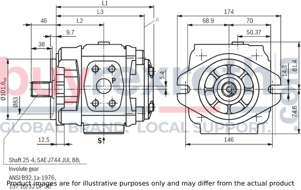
Frame size 4
PGH4-3X/...RE...VU2
PGH4-3X/...LE...VU2
Drive shaft cylindrical,
SAE 2-hole mounting flange
|
Type |
NG |
Part number “R” clockwise rotation |
“L” counterclockwise rotation |
L1 |
L2 |
L3 |
S 1) |
P 1) |
|
PGH4‑3X/020..E11VU2 |
R901147100 |
upon request |
145 mm |
70,5 mm |
129 mm |
1″ S |
3/4″ H |
|
|
PGH4‑3X/025..E11VU2 |
R901147101 |
upon request |
150 mm |
73 mm |
134 mm |
1 1/4″ S |
3/4″ H |
|
|
PGH4‑3X/032..E11VU2 |
R901147102 |
upon request |
157 mm |
76,5 mm |
141 mm |
1 1/2″ S |
1″ H |
|
|
PGH4‑3X/040..E11VU2 |
R901147103 |
upon request |
164 mm |
80 mm |
148 mm |
1 1/2″ S |
1″ H |
|
|
PGH4‑3X/050..E11VU2 |
R901147104 |
upon request |
174 mm |
85 mm |
158 mm |
2″ S |
1″ H |
|
| 1) |
S = standard pressure series, H = high-pressure series; for the exact dimensions see table Connections |
Dimensions in mm

2) With multiple pumps, the combination part will start from here
The figure shows a pump with clockwise rotation; with a pump with counterclockwise rotation, the pressure port is on the opposite side!
PGH4-3X/... RE...VE4
Drive shaft cylindrical,
4-hole mounting flange according to ISO 3019-2 and VDMA 24560
|
Type |
NG |
Part number “R” clockwise rotation |
L1 |
L2 |
L3 |
S 1) |
P 1) |
|
PGH4-3X/020RE11VE4 |
R901147105 |
145 mm |
70,5 mm |
129 mm |
1″ S |
3/4″ H |
|
|
PGH4-3X/025RE11VE4 |
R901147106 |
150 mm |
73 mm |
134 mm |
1 1/4″ S |
3/4″ H |
|
|
PGH4-3X/032RE11VE4 |
R901147107 |
157 mm |
76,5 mm |
141 mm |
1 1/2″ S |
1″ H |
|
|
PGH4-3X/040RE11VE4 |
R901147108 |
164 mm |
80 mm |
148 mm |
1 1/2″ S |
1″ H |
|
|
PGH4-3X/050RE11VE4 |
R901147109 |
174 mm |
85 mm |
158 mm |
2″ S |
1″ H |
|
| 1) |
S = standard pressure series, H = high-pressure series; for the exact dimensions see table Connections |
Dimensions in mm
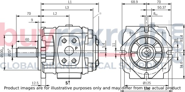
2) With multiple pumps, the combination part will start from here
PGH4-3X/...RR...VU2
PGH4-3X/...LR...VU2
Drive shaft geared, SAE 2-hole mounting flange
(central and back pump in pump combinations)
|
Type |
NG |
Part number |
L1 |
L2 |
L3 |
S 1) |
P 1) |
|
|
“R” clockwise rotation |
“L” counterclockwise rotation |
|||||||
|
PGH4-3X/020..R11VU2 |
R901147110 |
upon request |
145 mm |
70,5 mm |
129 mm |
1″ S |
3/4″ H |
|
|
PGH4-3X/025..R11VU2 |
R901147111 |
upon request |
150 mm |
73 mm |
134 mm |
1 1/4″ S |
3/4″ H |
|
|
PGH4-3X/025..R11VU2 |
R901147112 |
upon request |
157 mm |
76,5 mm |
141 mm |
1 1/2″ S |
1″ H |
|
|
PGH4-3X/040..R11VU2 |
R901147113 |
upon request |
164 mm |
80 mm |
148 mm |
1 1/2″ S |
1″ H |
|
|
PGH4-3X/050..R11VU2 |
R901147114 |
upon request |
174 mm |
85 mm |
158 mm |
2″ S |
1″ H |
|
| 1) |
S = standard pressure series, H = high-pressure series; for the exact dimensions see table Connections |
Dimensions in mm
2) With multiple pumps, the combination part will start from here
Frame size 5
PGH5-3X/...RE...VU2
PGH5-3X/...LE...VU2
Drive shaft cylindrical, SAE 2-hole mounting flange
|
Type |
NG |
Part number |
L1 |
L2 |
L3 |
S 1) |
P 1) |
|
|
“R” clockwise rotation |
“L” counterclockwise rotation |
|||||||
|
PGH5-3X/063..E11VU2 |
R901147115 |
upon request |
210 mm |
105,5 mm |
194 mm |
2″ S |
1 1/4″ H |
|
|
PGH5-3X/080..E11VU2 |
R901147116 |
upon request |
218 mm |
109,5 mm |
202 mm |
2″ S |
1 1/4″ H |
|
|
PGH5-3X/100..E11VU2 |
R901147117 |
upon request |
227 mm |
114 mm |
211 mm |
2 1/2″ S |
1 1/2″ H |
|
|
PGH5-3X/125..E11VU2 |
R901147118 |
upon request |
239 mm |
120 mm |
223 mm |
2 1/2″ S |
1 1/2″ H |
|
|
PGH5-3X/160..E11VU2 |
R901147119 |
upon request |
257 mm |
129 mm |
241 mm |
3″ S |
2″ H |
|
|
PGH5-3X/200..E07VU2 |
R901147120 |
upon request |
275 mm |
138 mm |
259 mm |
3 1/2″ S |
2″ S |
|
|
PGH5-3X/250..E07VU2 |
R901147121 |
upon request |
299 mm |
150 mm |
283 mm |
3 1/2″ S |
2 1/2″ S |
|
| 1) |
S = standard pressure series, H = high-pressure series; for the exact dimensions see table Connections |
Dimensions in mm
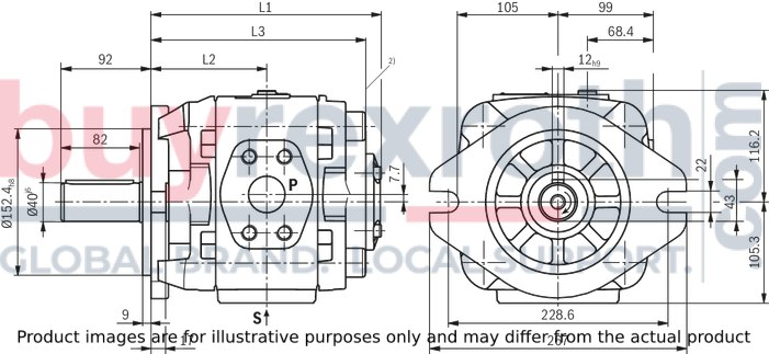
2) With multiple pumps, the combination part will start from here
PGH5-3X/...RE...VE4
Drive shaft cylindrical,
4-hole mounting flange according to ISO 3019-2 and VDMA 24560
|
Type |
NG |
Part number |
L1 |
L2 |
L3 |
S 1) |
P 1) |
|
“R” clockwise rotation |
|||||||
|
PGH5-3X/063RE11VE4 |
R901147122 |
210 mm |
105,5 mm |
194 mm |
2″ S |
1 1/4″ H |
|
|
PGH5-3X/080RE11VE4 |
R901147123 |
218 mm |
109,5 mm |
202 mm |
2″ S |
1 1/4″ H |
|
|
PGH5-3X/100RE11VE4 |
R901147124 |
227 mm |
114 mm |
211 mm |
2 1/2″ S |
1 1/2″ H |
|
|
PGH5-3X/125RE11VE4 |
R901147125 |
239 mm |
120 mm |
223 mm |
2 1/2″ S |
1 1/2″ H |
|
|
PGH5-3X/160RE11VE4 |
R901147126 |
257 mm |
129 mm |
241 mm |
3″ S |
2″ H |
|
|
PGH5-3X/200RE07VE4 |
R901147127 |
275 mm |
138 mm |
259 mm |
3 1/2″ S |
2″ S |
|
|
PGH5-3X/250RE07VE4 |
R901147128 |
299 mm |
150 mm |
283 mm |
3 1/2″ S |
2 1/2″ S |
|
| 1) |
S = standard pressure series, H = high-pressure series; for the exact dimensions see table Connections |
Dimensions in mm
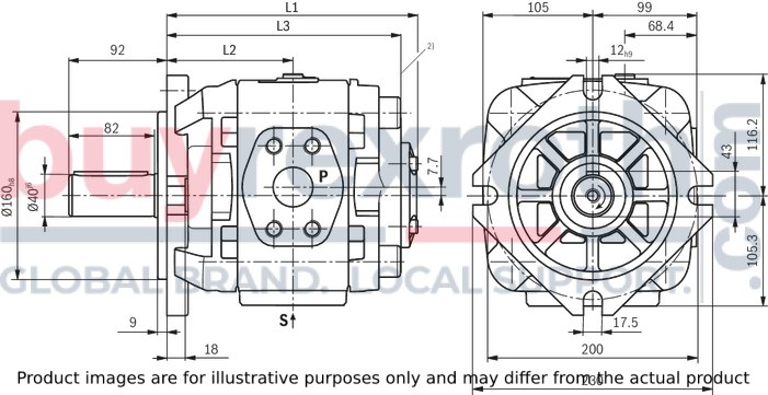
2) With multiple pumps, the combination part will start from here
PGH5-3X/...RR...VU2
PGH5-3X/...LR...VU2
Drive shaft geared, SAE 2-hole mounting flange
(central and back pump for pump combinations)
|
Type |
NG |
Part number |
L1 |
L2 |
L3 |
S 1) |
P 1) |
|
“R” clockwise rotation |
|||||||
|
PGH5-3X/063RE11VE4 |
R901147122 |
210 mm |
105,5 mm |
194 mm |
2″ S |
1 1/4″ H |
|
|
PGH5-3X/080RE11VE4 |
R901147123 |
218 mm |
109,5 mm |
202 mm |
2″ S |
1 1/4″ H |
|
|
PGH5-3X/100RE11VE4 |
R901147124 |
227 mm |
114 mm |
211 mm |
2 1/2″ S |
1 1/2″ H |
|
|
PGH5-3X/125RE11VE4 |
R901147125 |
239 mm |
120 mm |
223 mm |
2 1/2″ S |
1 1/2″ H |
|
|
PGH5-3X/160RE11VE4 |
R901147126 |
257 mm |
129 mm |
241 mm |
3″ S |
2″ H |
|
|
PGH5-3X/200RE07VE4 |
R901147127 |
275 mm |
138 mm |
259 mm |
3 1/2″ S |
2″ S |
|
|
PGH5-3X/250RE07VE4 |
R901147128 |
299 mm |
150 mm |
283 mm |
3 1/2″ S |
2 1/2″ S |
|
| 1) |
S = standard pressure series, H = high-pressure series; for the exact dimensions see table Connections |
Dimensions in mm
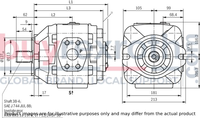
Ports
Suction port "S"

Pressure port "P"
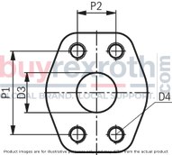
|
BG |
NG |
Porting pattern / suction port S |
D1 |
D2 |
S1 |
S2 |
Porting pattern / pressure port P |
D3 |
D4 |
P1 |
P2 |
|
4 |
020 |
1″ 344,7 bar |
Ø25 mm |
M10; 18 |
52,4 mm |
26,2 mm |
3/4″ 413,7 bar |
Ø19 mm |
M10; 18 |
50,8 mm |
23,8 mm |
|
025 |
1 1/4″ 275,8 bar |
Ø32 mm |
M10; 18 |
58,7 mm |
30,2 mm |
3/4″ 413,7 bar |
Ø19 mm |
M10; 18 |
50,8 mm |
23,8 mm |
|
|
032 |
1 1/2″ 206,8 bar |
Ø38 mm |
M12; 21 |
69,9 mm |
35,7 mm |
1″ 413,7 bar |
Ø25,4 mm |
M12; 23 |
57,2 mm |
27,8 mm |
|
|
040 |
1 1/2″ 206,8 bar |
Ø38 mm |
M12; 21 |
69,9 mm |
35,7 mm |
1″ 413,7 bar |
Ø25,4 mm |
M12; 23 |
57,2 mm |
27,8 mm |
|
|
050 |
2″ 206,8 bar |
Ø51 mm |
M12; 21 |
77,8 mm |
42,9 mm |
1″ 413,7 bar |
Ø25,4 mm |
M12; 23 |
57,2 mm |
27,8 mm |
|
|
5 |
063 |
2″ 206,8 bar |
Ø51 mm |
M12; 21 |
77,8 mm |
42,9 mm |
1 1/4″ 413,7 bar |
Ø32 mm |
M12; 21 |
66,6 mm |
31,8 mm |
|
080 |
2″ 206,8 bar |
Ø51 mm |
M12; 21 |
77,8 mm |
42,9 mm |
1 1/4″ 413,7 bar |
Ø32 mm |
M12; 21 |
66,6 mm |
31,8 mm |
|
|
100 |
2 1/2″ 172,3 bar |
Ø64 mm |
M12; 23 |
88,9 mm |
50,8 mm |
1 1/2″ 413,7 bar |
Ø38 mm |
M16; 30 |
79,3 mm |
36,5 mm |
|
|
125 |
2 1/2″ 172,3 bar |
Ø64 mm |
M12; 23 |
88,9 mm |
50,8 mm |
1 1/2″ 413,7 bar |
Ø38 mm |
M16; 30 |
79,3 mm |
36,5 mm |
|
|
160 |
3″ 137,9 bar |
Ø76 mm |
M16; 30 |
106,4 mm |
61,9 mm |
2″ 413,7 bar |
Ø51 mm |
M20; 35 |
96,8 mm |
44,5 mm |
|
|
200 |
3 1/2″ 34,5 bar |
Ø89 mm |
M16; 30 |
120,7 mm |
69,9 mm |
2″ 206,8 bar |
Ø51 mm |
M12; 23 |
77,8 mm |
42,9 mm |
|
|
250 |
3 1/2″ 34,5 bar |
Ø89 mm |
M16; 30 |
120,7 mm |
69,9 mm |
2 1/2″ 172,4 bar |
Ø64 mm |
M12; 23 |
88,9 mm |
50,8 mm |
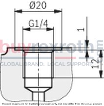
Measuring port PGH4-3X/... and PGH5-3X/...
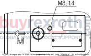
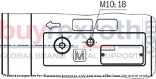
Dimensions in mm
Transport thread PGH4-3X/...
Transport thread PGH5-3X/...
Pump combinations
The dimensional drawings show the front pump and the combination part.
Combination part PGH5-3X+GF3-3X/VV1-1X/VV2-1X/K02
Material no.: R901155282
Dimensions in mm
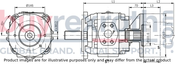
|
PGH5-3X... Size |
PGH5-3X/..RE..U2 |
PGH5-3X/..RR..U2 |
|
63 |
264 mm |
273 mm |
|
80 |
272 mm |
281 mm |
|
100 |
281 mm |
290 mm |
|
125 |
293 mm |
302 mm |
|
160 |
311 mm |
320 mm |
|
200 |
329 mm |
338 mm |
|
250 |
353 mm |
362 mm |
|
PGF3/PGP2 Size |
L2 |
L3 |
|
20 |
144,5 mm |
79,5 mm |
|
22 |
146,5 mm |
80,5 mm |
|
25 |
150,5 mm |
82,5 mm |
|
32 |
159,5 mm |
87 mm |
|
40 |
169,5 mm |
92 mm |
|
PVV..UMB Frame size |
L2 |
L3 (P) |
L4 (S) |
|
1 |
156 mm |
133 mm |
63,5 mm |
|
2 |
163 mm |
38 mm |
120,5 mm |
The dimensional drawings show the front pump and the combination part.
Combination part PGH5-3X+GH2/3-2X/GF2-2X/AZPF-1X/K01
Material no. : R901155283
Dimensions in mm
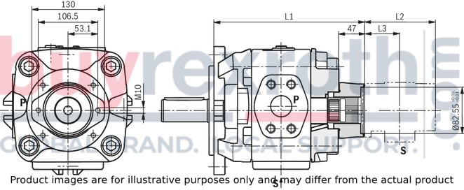
|
PGH5-3X... Size |
PGH5-3X/..RE..U2 |
PGH5-3X/..RR..U2 |
|
63 |
241 mm |
250 mm |
|
80 |
249 mm |
258 mm |
|
100 |
258 mm |
267 mm |
|
125 |
270 mm |
279 mm |
|
160 |
288 mm |
297 mm |
|
200 |
306 mm |
315 mm |
|
250 |
330 mm |
339 mm |
|
PGF2/PGP2 Size |
L2 |
L3 |
|
006 |
116 mm |
65 mm |
|
008 |
119,5 mm |
167 mm |
|
011 |
125 mm |
69,5 mm |
|
013 |
130 mm |
72 mm |
|
016 |
135 mm |
74,5 mm |
|
019 |
141 mm |
77,5 mm |
|
022 |
147 mm |
80,5 mm |
|
PGH2 Size |
L2 |
L3 |
|
005 |
110 mm |
54 mm |
|
006 |
112,5 mm |
55,5 mm |
|
008 |
116 mm |
57 mm |
|
PGH3 Size |
L2 |
L3 |
|
011 |
121,5 mm |
60 mm |
|
013 |
126,5 mm |
62,5 mm |
|
016 |
131,5 mm |
65 mm |
|
AZPF Size |
L2 |
L3 |
|
004 |
85 mm |
40 mm |
|
005 |
87,5 mm |
41 mm |
|
008 |
91,5 mm |
43 mm |
|
011 |
96,5 mm |
47 mm |
|
014 |
101,5 mm |
47,5 mm |
|
016 |
105 mm |
47,5 mm |
|
019 |
110 mm |
47,5 mm |
|
022 |
115,5 mm |
55 mm |
The dimensional drawings show the front pump and the combination part.
Combination part PGH5-3X+GH4-3X..R
Material no.: R901155284
Dimensions in mm
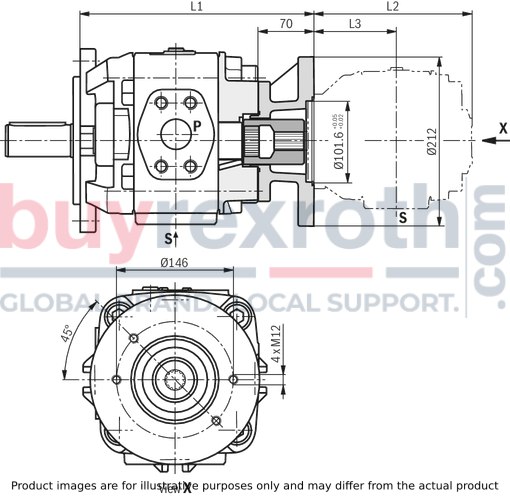
|
PGH5-3X.. Size |
PGH5-3X/..RE..U2 |
PGH5-3X/..RR..U2 |
|
63 |
264 mm |
273 mm |
|
80 |
272 mm |
281 mm |
|
100 |
281 mm |
290 mm |
|
125 |
293 mm |
302 mm |
|
160 |
311 mm |
320 mm |
|
200 |
329 mm |
338 mm |
|
250 |
353 mm |
362 mm |
|
PGH4-3X…R..U2 Size |
L2 |
L3 |
|
20 |
145 mm |
70,5 mm |
|
25 |
150 mm |
73 mm |
|
32 |
157 mm |
76,5 mm |
|
40 |
164 mm |
80 mm |
|
50 |
174 mm |
85 mm |
The dimensional drawings show the front pump and the combination part.
Combination part PGH5-3X+GH5-3X..R
Material no.: R901155285
Dimensions in mm
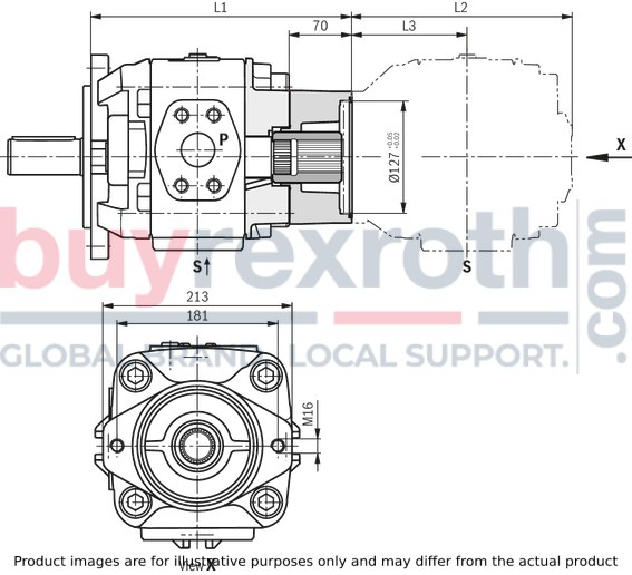
|
PGH5-3X.. Size |
PGH5-3X/..RE..U2 |
PGH5-3X/..RR..U2 |
|
63 |
264 mm |
273 mm |
|
80 |
272 mm |
281 mm |
|
100 |
281 mm |
290 mm |
|
125 |
293 mm |
302 mm |
|
160 |
311 mm |
320 mm |
|
200 |
329 mm |
338 mm |
|
250 |
353 mm |
362 mm |
|
PGH5-3X…R..U2 Size |
L2 |
L3 |
|
63 |
219 mm |
114,5 mm |
|
80 |
227 mm |
118,5 mm |
|
100 |
236 mm |
123 mm |
|
125 |
248 mm |
129 mm |
|
160 |
266 mm |
138 mm |
|
200 |
284 mm |
147 mm |
|
250 |
308 mm |
159 mm |
The dimensional drawings show the front pump and the combination part.
Combination part: PGH5-3X+VV4/5-1X..J
Material no.: R901155286
Dimensions in mm

|
PGH5-3X.. Size |
PGH5-3X/..RE..U2 |
PGH5-3X/..RR..U2 |
|
63 |
264 mm |
273 mm |
|
80 |
272 mm |
281 mm |
|
100 |
281 mm |
290 mm |
|
125 |
293 mm |
302 mm |
|
160 |
311 mm |
320 mm |
|
200 |
329 mm |
338 mm |
|
250 |
353 mm |
362 mm |
|
Type |
NG |
Part number |
L1 |
L2 |
L3 |
S 1) |
P 1) |
|
|
“R” clockwise rotation |
“L” counterclockwise rotation |
|||||||
|
PGH5-3X/063..R11VU2 |
R901147129 |
upon request |
219 mm |
114,5 mm |
203 mm |
2″ S |
1 1/4″ H |
|
|
PGH5-3X/080..R11VU2 |
R901147130 |
upon request |
227 mm |
118,5 mm |
211 mm |
2″ S |
1 1/4″ H |
|
|
PGH5-3X/100..R11VU2 |
R901147131 |
upon request |
236 mm |
123 mm |
220 mm |
2 1/2″ S |
1 1/2″ H |
|
|
PGH5-3X/125..R11VU2 |
R901147132 |
upon request |
248 mm |
129 mm |
232 mm |
2 1/2″ S |
1 1/2″ H |
|
|
PGH5-3X/160..R11VU2 |
R901147133 |
upon request |
266 mm |
138 mm |
250 mm |
3″ S |
2″ H |
|
|
PGH5-3X/200..R07VU2 |
R901147134 |
upon request |
284 mm |
147 mm |
268 mm |
3 1/2″ S |
2″ S |
|
|
PGH5-3X/250..R07VU2 |
R901147135 |
upon request |
308 mm |
159 mm |
292 mm |
3 1/2″ S |
2 1/2″ S |
|
| 1) |
S = standard pressure series, H = high-pressure series; for the exact dimensions see table Connections |
1. General information
This project planning information refers to the specific properties of the Rexroth PGH.-3X internal gear pump.
Comprehensive general information and suggestions are contained in the Hydraulics Trainer, volume 3 "Project planning information and design of hydraulic systems", RE 00281.
1.1 Intended use
Rexroth internal gear pumps are intended for the set-up of hydraulic drive systems in mechanical engineering and plant construction. During project planning, the basic principles of the EU Machinery Directive or comparable national regulations outside the EU have to be observed.
They must not be used in potentially explosive environments in accordance with directive 94/9/EC (ATEX).
1.2 Technical data
The plant or machine manufacturer must ensure compliance with the admissible technical data and operating conditions. The pump itself does not contain a device to prevent operation outside the admissible data.
All specified technical performance features are average values and apply with the specified boundary conditions. In case of modifications to the basic conditions (e.g. viscosity), the technical data may change as well. Distribution corresponding to the relevant state-of-the-art is possible.
Operating the pump outside of the admissible technical data is possible to a certain extent, however, this requires the explicit written approval by Bosch Rexroth.
2. Hydraulic project planning
2.1 Bleeding option for commissioning
For Rexroth internal gear pumps PGM.-3X, a manual, switchable or automatic bleeding option for the initial commissioning or any re-commissioning after maintenance and repair works is to be provided. As bleeding point, you can use the measuring port (M) located at the pump. Otherwise, the bleeding point has to be put into the pressure line in front of the first valve or check valve. Bleeding may only be effected with a maximum counter pressure of 0.2 bar.
Examples of bleedings circuits:
1. Automatic bleeding via self-acting bleed valve
2. Switchable bleeding
3. Manually operated bleeding
Automatic bleeding via self-acting bleed valve

Switchable bleeding

Manually operated bleeding

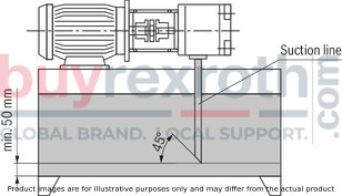
2.2 Suction line
The line cross-sections have to be rated for the designed flows in a manner that an ideal suction speed of 0.6 to 1.2 m/s is achieved on average. The suction speed must not exceed a maximum value of 2 m/s.
The suction cross-sections at the pump itself are designed for the maximum flow and can therefore only be used as reference. In case of continuous operation with speeds lower than the admissible maximum speed, the suction tube diameter is to be dimensioned smaller than the suction port of the pump in accordance with the actual suction speed.
All in all, the suction line is to be designed so that the admissible inlet operating pressure is complied with (0.8 to 2 bar absolute)! Bends and the combination of the suction pipes of several pumps are to be avoided. If suction filters have to be used, it has to be ensured on the system side that the lowest admissible inlet operating pressure is not exceeded even when the filter is contaminated.
Please ensure air tightness of the transitions and dimensional stability of the suction tube as regards to the external air pressure.
The immersion depth of the suction pipe should be as large as possible. Dependent on the internal tank pressure, the viscosity of the operating medium and the flow ratios within the tank, no vortex must be formed even during maximum flow. Otherwise, there is the risk that air is sucked in.
We recommend selecting suction pipes according to AB 23-03.
Dimensions in mm
2.3 Pressure line
For pressure lines, make sure that sufficient bursting protection of the pipes, hoses and connection elements is provided. The cross-sections should be based on the maximum flow in order to avoid additional excessive load of the pump due to back pressure. Here, you must also consider the pipe losses over the entire pressure line length and other line resistances (e.g. bends, pressure filters).
2.4 Pressure limitation
The PGH internal gear pump does not comprise any device for compliance with the maximum operating pressure. Setting and limiting the admissible operating pressure has to be ensured on the system side.
The pressure relief valves necessary for that purpose are to be designed considering the maximum flow and the existing pressure increase speed so that the admissible intermittent operating pressure is not exceeded.
2.5 Pressure holding function
In the variable-speed drive, the pump can temporarily also be operated below the specified minimum speed, in the pressure holding function. The holding time and the speed necessary for that purpose results dependent on the operating viscosity and the pressure level. For the design, please contact Bosch Rexroth's technical sales department.
In the deactivated state (speed = 0), a leakage flow flows through the pump back into the tank, dependent on the load pressure. Use a check valve to prevent this.
When using a check valve, please observe the information on bleeding in chapter 2.1.
3. Mechanical project planning
3.1 Disassembly and installation option
For disassembling and mounting the pump on the drive, provide guaranteed access on the system side by means of suitable lifting gear. Please consider particularly the net mass of frame size PGH5 (see "Technical data”).
Provide screws of property class 8.8 or 10.9 for mounting purposes.
3.2 Mounting
The screws must be accessible on the machine-side so that the required tightening torque can be applied. The tightening torque of the screws is based on the operating conditions and involved elements of the screw connection and must be specified by the manufacturer in the power unit, machine or system project planning.
3.3 Tank
In the tank construction or the selection of suitable standard tanks, the following requirements are to be observed: Selection of the largest tank volume possible, dependent on the permanent or average flow, in order to allow for the separation of air bubbles by means of sufficient duration time of the medium in the tank. The air release capacity of the fluid used is also of importance. Provision of settling zones for the fluid in the tank in order to allow for air release. Provision of guiding plates in order to allowing for the deposit of contamination at the tank bottom outside the pump suction area. Large dimensioning of the tank surfaces dependent on the heat output to be dissipated via the tank walls.
3.4 Required power unit functions
Hydraulic power units should at least be equipped with the following features: Tanks, where internal pressure corresponds to the ambient pressure in accordance with the design, must be equipped with breathing filters for pressure compensation purposes. For fluid filling, only use filling connections excluding filling with unfiltered hydraulic fluid. The ingress of contamination or humidity must be avoided. In case of use in highly contaminated environments, the tank must to this end be pre-tensioned by means of air pressure. If cleansing of the external tank side is intended or to be expected during the period of use, select tank fittings for pipes, lines, or hoses, which ensure safe sealing against external pressurization with water jet.
3.5 Place of installation and environmental conditions
With places of installation from a geodetic height of more than 1000 m, the pump is to be arranged in or below the tank or the tank is to be pre-tensioned by means of compressed air in order to comply with the admissible minimum inlet pressure. A short suction line with large cross-section has to be selected, bends should not to be used.
When installing the pump more than 10 m below the tank, the reduction of the inlet pressure to the maximum admissible value must be ensured by means of additional measures.
When operating the pump in salt-containing or corrosive environments or when pressure loading with strongly abrasive substances is possible, make sure on the system side that the shaft seal ring and the sealing area of the shaft do not make direct contact with the environment.
3.6 Installation positions
B3

B5

V1

V2

Attention!
Installation position motor at bottom and pump at top (e.g. IM V2) is not admissible!
4. Pump combinations
For pump combinations, make sure that the admissible operating data for the relevant pump type are complied with in every stage. The combined pumps must all have the same direction of rotation. The pump with the highest torque, variable displacement pumps or pumps with intermittent load should be provided as first stage in the pump combination. The maximum through-drive torque must be checked by the project planner for every application. This is also true for already existing (coded) pump combinations. The drive torque of a pump stage is calculated as follows:
T : Torque in Nm
Δp : Operating pressure in bar
V : Displacement in cm3
η : hydraulic, mechanical efficiency
maximum admissible torques in Nm:
|
Type |
Input torque |
Input torque |
|
|
cylindrical shaft ..E |
geared shaft ..R |
||
|
PGH4 |
450 |
450 |
280 |
|
PGH5 |
1100 |
1400 |
700 |
5. Maintenance schedule and operational safety
For safe operation and a long life cycle of the pump, a maintenance schedule has to be developed for the power unit, the machine, or the system. The maintenance schedule must ensure that the intended or admissible operating conditions of the pump are complied with over the entire period of use.
In particular, compliance with the following operating parameters has to be ensured:
the required oil cleanliness the operating temperature range the filling level of the operating mediumFurthermore, the pump and the system have to be checked for modifications of the following parameters on a regular basis:
Vibrations Noise Temperature difference pump – fluid in the tank Foam formation in the tank Leak-tightnessModifications of these parameters indicate wear of components (e.g. drive motor, coupling, pump, etc.).
The cause must be identified and remedied immediately.
In order to achieve high operational safety of the pump in the machine or system, we recommend checking the parameters mentioned above continuously and automatically and shutting the system off automatically in case of modifications exceeding the usual fluctuations in the intended operating range.
Plastic components of drive couplings should be replaced regularly, however, after 5 years at the latest. The relevant manufacturer's specifications must be considered and be given priority.
For preventive maintenance of the pump, we recommend having the seals replaced after a maximum operating time of 5 years by an authorized Bosch Rexroth service company.
6. Accessories
6.1 SAE connection flanges
We recommend selecting the SAE flanges for suction and pressure port according to AB 22-15 (with welded connection) or AB 22-13 (with threaded connection).
6.2 Pump safety block
For limiting the operating pressure and for the pump circulation at zero pressure, we recommend our pump safety blocks type DBA… according to RE 25890.
Automatic bleeding during commissioning is, however, not possible via DBA blocks. In this connection, we recommend a separate manual or automatic bleeding, e.g. via the pump's measuring port (see Hydraulic project planning)!
6.3 Other accessories
To install the Rexroth PGH.-3X internal gear pump on electric motors, we recommend selecting the pump carriers according to AB 41-20 and torsionally flexible couplings according to AB 33-22.
Related Products
R901479592
$1,330.00 USD
R901147120
$9,373.00 USD
R901253293
$5,658.00 USD
R987208503
$1,632.00 USD
R901089555
$3,332.00 USD


