


LC25B02E7X/V
Manufacturer: Bosch Rexroth
Material #: R901116294
Model : LC25B02E7X/V
***Disclaimer: The following summary contains information gathered from various sources such as product descriptions, technical specifications and catalogs. While efforts have been made to provide accurate details, inaccuracies may occur. It is advised to verify all information by contacting Bosch Rexroth directly.***
The Bosch Rexroth LC25B02E7X/V (R901116294) is a high-quality way cartridge valve designed for seamless integration into a compact block design. This product offers versatility for various hydraulic applications by allowing pressure, directional, and throttle functions or a combination thereof. Its efficient design is tailored for different flow rates in actuators, providing cost-effective solutions when applying multiple functions.
The LC25B02E7X/V consists of a control cover that houses control bores and may include additional features like stroke limitation, hydraulically controlled directional seat valves, or shuttle valves based on the overall function required. Moreover, it can be fitted with electrically operated directional spool or seat valves if necessary. The installation kit includes essential components such as a bushing, ring (only up to NG), valve poppet (available with or without damping nose), and closing spring.
This particular model operates based on pressure dependency, establishing three primary pressurized areas—A1, A2, A3—to facilitate its function. The valve seat area A1 serves as the reference point while annulus area A2 varies depending on the version of the cartridge valve, affecting the overall area ratio and consequently the function of area A3. The combination of areas A1 and A2 contributes to opening forces while area A3 alongside the spring influences closing forces. These dynamics determine the spool position within the valve.
Designed for robust performance, this way cartridge valve can manage flow from port A to B or vice versa with precision. It ensures channel A remains blocked without leakage when pressurization occurs in area A3 through pilot oil discharge from channel B or an external pilot oil supply.
The LC25B02E7X/V is part of Bosch Rexroth's standard series in size 25 and belongs to component series X0 to X9. It is capable of handling maximum operating pressures up to bar levels and can accommodate maximum flows measured in liters per minute. This product offers different cracking pressures through its choice of valve poppets with or without damping noses and varying area ratios to suit specific application requirements.
$424.00 USD
More are expected on November 18, 2024
Status: This product is temporarily out of stock.
Qty: Delivered as early as November 18, 2024 when ordered in
This product is eligible for factory repair.
2-way cartridge valves are elements that have been designed for a compact block design. The power section with connections A and B is installed into the control block in a receiving hole standardized according to ISO 7368 and closed with a cover. In most cases, the cover is also the connection from the control side of the power section to the pilot control valves.
By control with respective pilot control valves, the power section can be applied for pressure, directional and throttle functions or a combination of these functions. Particularly efficient solutions are realized by adjustment of the size to various flows of the individual ways of an actuator. The application of power sections of elements for multiple functions is very cost-effective.
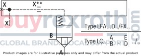
2-way cartridge valves generally consist of control cover (1) and installation kit (2). The control cover contains the control bores and optionally a stroke limitation function, a hydraulically controlled directional seat valve or a shuttle valve according to the required overall function. Additionally, electrically operated directional spool or seat valves can be installed at a control cover. The installation kit consists of a bushing (3), ring (4) (only up to NG32), valve poppet (5), optionally with damping nose (6) or without damping nose (7) as well as closing spring (8).
The function of 2-way cartridge valves is pressure-dependent. This way, three crucial pressurized areas are realized for the function. A1, A2, A3. The area at valve seat A1 is observed as 100 %. Depending on the version, the annulus area A2 realized by grading is 7 % or 50 % of area A1. The area ratio A1 : A2 is respectively either 14.3 : 1 or 2 : 1. The area A3 is identical to the sum of areas A1 + A2. Due to the different area ratios A1 : A2 and the resulting different annulus areas (A2), the area A3 is one time 107 % and another time 150 % of the area A1 at the seat, which is observed as 100 %.
In general, the following applies:
The areas A1 and A2 are effective in opening direction. The area A3 and the spring are effective in closing direction. The direction of action of the resulting force from the opening and closing forces determines the spool position of the 2-way cartridge valve.
The 2-way cartridge valves can be passed from A to B or from B to A. Pressurization of area A3 by pilot oil discharge from channel B or external pilot oil supply, channel A is blocked without leakage.

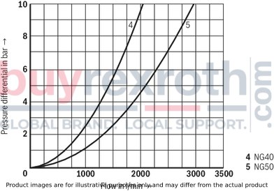
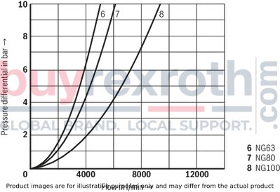
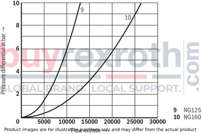
(simulated with HLP46, ϑoil = 40±5 °C)
Without damping nose "E", A → B
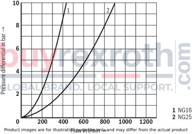
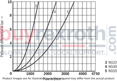
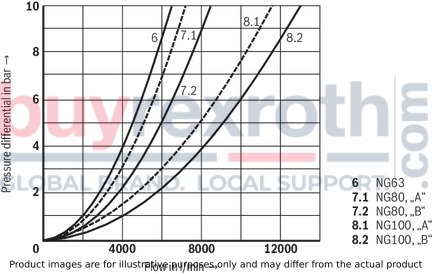
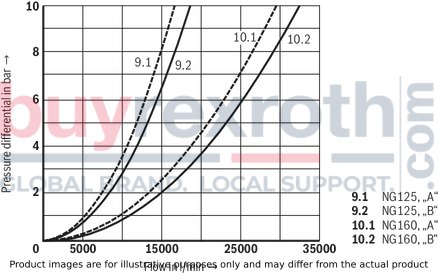
Without damping nose "E", B → A
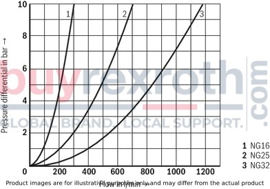
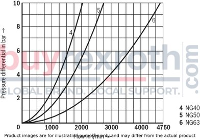

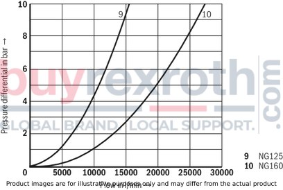
With damping nose “D”, A → B
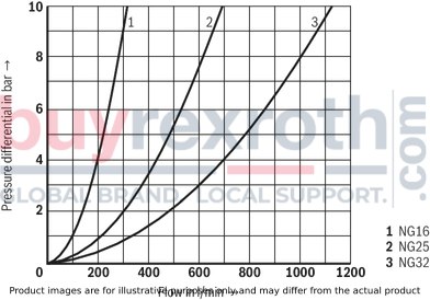
With damping nose "D", B → A
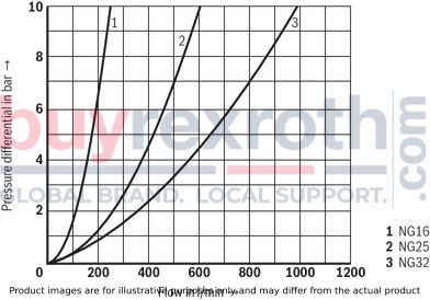
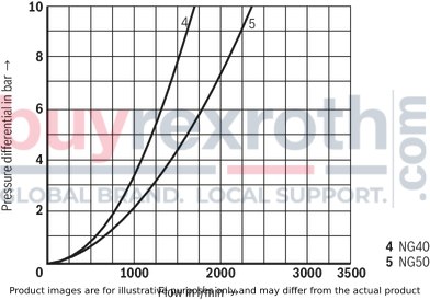
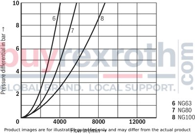
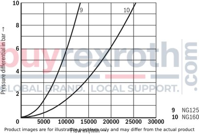
Notice:
The specified characteristic curves were simulated with 100% spool stroke and an aligned socket (see sketch under recommended socket alignment). The simulation results were validated by measurement results. The basis was an installation geometry with ØD3* (see installation under dimensions) and a simulation model according to ISO 4411/2008-10-01.
Recommended socket alignment:
Size 16...32
Bore on bore

Size 40 ... 160
Bar on bore

|
Version "E" |
Version “D” |
||

|

|

|

|
|
Area ratio A1 : A2 = 2 : 1 Version "…A.E…" |
Area ratio A1 : A2 = 14,3 : 1 Version "…B.E…" |
Area ratio A1 : A2 = 2 : 1 Version "…A.D…" |
Area ratio A1 : A2 = 14,3 : 1 Version "…B.D…" |
Additional functions with special numbers see "Information".
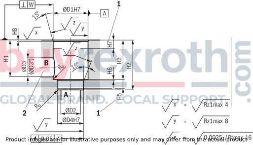
Installation bore according to ISO 7368
Dimensions in mm
|
1 |
Depth of fit |
|
2 |
Port B may be positioned around the central axis of port A. However, it must be observed that the mounting bores and the control bores are not damaged. |
|
NG |
16 | 25 | 32 | 40 | 50 | 63 | 80 | 100 | 125 | 160 | |
|
ØD1H7 |
mm |
32 | 45 | 60 | 75 | 90 | 120 | 145 | 180 | 225 | 300 |
|
ØD2 |
mm |
16 | 25 | 32 | 40 | 50 | 63 | 80 | 100 | 150 1) | 200 1) |
|
ØD3 |
mm |
16 | 25 | 32 | 40 | 50 | 63 | 80 | 100 | 125 | 160 |
|
(ØD3*) 2) |
mm |
25 | 32 | 40 | 50 | 63 | 80 | 100 | 125 | 160 | 250 |
|
ØD4H7 |
mm |
25 | 34 | 45 | 55 | 68 | 90 | 110 | 135 | 200 | 270 |
|
H1 |
mm |
42.5 | 57 | 68.5 | 84.5 | 97.5 | 127 | 170.5 | 205.5 | 255 | 368 |
|
H2 |
mm |
56 | 72 | 85 | 105 | 122 | 155 | 205 | 245 | 300 | 425 |
|
mm |
+ 0.1 | + 0.1 | + 0.1 | + 0.1 | + 0.1 | + 0.1 | + 0.1 | + 0.1 | + 0.15 | + 0.15 | |
|
H3 |
mm |
43 | 58 | 70 | 87 | 100 | 130 | 175 | 210 | 257 | 370 |
|
mm |
+ 0.2 | + 0.2 | + 0.2 | + 0.3 | + 0.3 | + 0.3 | + 0.4 | + 0.4 | + 0.5 | + 0.5 | |
|
H5 |
mm |
11 | 12 | 13 | 15 | 17 | 20 | 25 | 29 | 31 | 45 |
|
H6 |
mm |
2 | 2.5 | 2.5 | 3 | 3 | 4 | 5 | 5 | 7 | 8 |
|
mm |
- | - | - | - | - | - | - | - | ± 0.5 | ± 0.5 | |
|
H7 |
mm |
20 | 30 | 30 | 30 | 35 | 40 | 40 | 50 | 40 | 50 |
|
H8 |
mm |
2 | 2.5 | 2.5 | 3 | 4 | 4 | 5 | 5 | 5.5 | 5.5 |
|
mm |
- | - | - | - | - | - | - | - | ± 0.2 | ± 0.2 | |
|
W |
mm |
0.05 | 0.05 | 0.1 | 0.1 | 0.1 | 0.1 | 0.1 | 0.1 | 0.1 | 0.1 |
|
Ro 1) |
mm |
2 | 2 | 2 | 4 | 4 | 4 | 4 | 4 | 4 | 6.3 |
|
Ru 1) |
mm |
1 | 1 | 1 | 1 | 1 | 1 | 1 | 1 | 1 | 1 |
| 1) | Maximum dimension |
| 2) | Due to the use of a bore with ØD3*, port B protrudes over the upper limit of the area intended in ISO 7368. This is, however, possible due to the sealing concept and reduces the pressure loss during flow through the valve. Thus, we recommend a bore with ØD3*. |
Additional functions with special numbers (upon request)
|
Symbol |
Type (examples) |
Size |
Description / special characteristic |
|
LC . A..D7X/-004 |
16 ... 50 |
With piston sealing (leakage-free) Larger spring installation space Special cover or intermediate cover "D19" required NG16 … 40: only with cracking pressure approx. 4 bar NG50 and 63: cracking pressure approx. 2 bar or higher; alternatively "without spring" |
|
LC . A..E7X/-004 |
16 ... 50 |
||
|
LC . B..E7X/-004 |
16 ... 63 |
||

|
LC . A..D6X/-104 |
80, 100 |
With piston sealing (leakage-free) as SO-004, however, no special cover required |
|
LC . A..E6X/-104 |
80, 100 |
||
|
LC . B..E6X/-104 |
80, 100 |
||
|
LC . A..D7X/-104 |
40 … 63 |
||
|
LC . A..E7X/-104 |
40 … 63 |
||
|
LC . A..E2X/-104 |
125, 160 |
||

|
LC . A05D6X/-054 |
16 |
Pulling logic with open zero position Special cover (e.g. "D54") required |
|
LC . A20D6X/-054 |
25 ... 32 |
||
|
LC . A05E6X/-054 |
16 |
||
|
LC . A..E6X/-054 |
25 ... 80 |
||
|
LC ./100 A20E6X/-054 |
32, 100 |
||
|
LC . B05E6X/-054 |
12 |
||
|
LC . B20E6X/-054 |
25 |
||
|
LC . A20D7X/-054 |
50 |
||
|
LC . A40D7X/-054 |
63 |
||
|
LC . A20E7X/-054 |
50 |
||
|
LC . A..E7X/-054 |
63 |
||

|
LC …7X/-135 |
16 … 40 |
Larger spool clearance |
|
LC …7X/-146 |
16 … 40 |
Larger spool clearance With piston sealing (leakage-free) Larger spring installation space Special cover or intermediate cover "D19" required |

|
LC . A..D7X/-R10 |
16 |
As standard, however, larger bushing outer diameter D1 and D4 1 mm |
|
LC . A20D7X/-R10 |
25 |
||
|
LC 1. A40E7X/-R10 |
16, 32 |
||
|
LC . A..E7X/-R10 |
25, 63 |
||
|
LC . A10E7X/-R10 |
40 |
||
|
LC . A05E7X/-R10 |
50 |
||
|
LC . B..D7X/-R10 |
25 |
||
|
LC . B10D7X/-R10 |
32 |
||
|
LC . B40E7X/-R10 |
25, 40 |
||
|
LC . B..E7X/-R10 |
50, 63 |
||
|
|
LC . A..D7X/-R20 |
16 |
As standard, however, larger bushing outer diameter D1 and D4 2 mm |
|
LC . A20D7X/-R20 |
25 |
||
|
LC 1. A40E7X/-R20 |
16, 32 |
||
|
LC . A..E7X/-R20 |
25, 63 |
||
|
LC . A10E7X/-R20 |
40 |
||
|
LC . A05E7X/-R20 |
50 |
||
|
LC . B..D7X/-R20 |
25 |
||
|
LC . B10D7X/-R20 |
32 |
||
|
LC . B40E7X/-R20 |
25, 40 |
||
|
LC . B..E7X/-R20 |
50, 63 |
||

|
LC . XAB00E-7X/ |
16 … 63 |
Blind element without spool Channel A - B connected For use with available LFA cover or in connection with a cover "LFA . D-7X/FX99" |

|
LC . XAF00E-7X/ |
16 … 63 |
Blind element without spool Channel A - F connected Channel B closed For use with available LFA cover or in connection with a cover "LFA . D-7X/FX99" |

|
LC . X00E-7X/ |
16 … 63 |
Blind element without spool All channels blocked For use with available LFA cover or in connection with a cover "LFA . D-7X/FX99" |
Related Products
R978022018
$690.00 USD
R900931192
$2,187.00 USD
R978017781
$405.00 USD
R978913031
$4,244.00 USD
R900423758
$1,841.00 USD


