LOGIC COVER LFA50DBW2-7X/315F08D12
Manufacturer: Bosch Rexroth
Material #: R901082418
Model : LFA50DBW2-7X/315F08D12
***Disclaimer: The following summary contains information gathered from various sources such as product descriptions, technical specifications and catalogs. While efforts have been made to provide accurate details, inaccuracies may occur. It is advised to verify all information by contacting Bosch Rexroth directly.***
The Bosch Rexroth LFA50DBW2-7X/315F08D12 (R901082418) is a sophisticated hydraulic control cover designed for use with way cartridge valves, offering precise pressure control in hydraulic systems. This product features manual pressure adjustment capabilities that can be deactivated if necessary, providing flexibility and reliability in managing system pressures. The installation surface adheres to ISO standards, ensuring compatibility with a wide range of equipment.
With a maximum pressure rating of 315 bar and designed for subplate mounting, this control cover is suitable for high-pressure applications. It includes NBR seals, making it compatible with various hydraulic fluids such as HL, HLP, HLPD, HVLP, HVLPD, and HFC. The product's size and hexagon specifications are tailored to meet the requirements of different systems.
The LFA50DBW2-7X/315F08D12 utilizes a pilot-operated valve mechanism in either seat or spool design. The power section is installed into a receiving hole standardized according to DIN ISO standards and closed with the control cover itself. Different pressure functions can be realized by combining cartridge valves with this control cover.
For the pressure relief function, the corresponding cartridge valve is designed as a seat valve without an area difference at port B; the set pressure determines when the spool opens to limit pressure according to characteristic curves. Similarly, for the pressure reducing function—with its rest position open—the spool is held open by spring force until reaching the set pressure where it closes to reduce port A's pressure.
This model also supports various pilot control valves for manual adjustments between specific ranges. With its versatile configuration options including directional valve unloading capabilities and circulation circuit functions—whether open or blocked—this Bosch Rexroth product offers robust solutions for complex hydraulic systems requiring reliable and precise pressure regulation.
$1,982.00 USD
More are expected on June 10, 2026
| Qty | Price | Savings |
|---|---|---|
| 5-24 | $1,932.45 USD | $49.55 USD |
| 25+ | $1,882.90 USD | $99.10 USD |
Status: This product is temporarily out of stock.
Qty: Delivered as early as June 10, 2026 when ordered in
This product is eligible for factory repair.
Size 50, manual maximum pressure adjustment that can be switched off, with installation surface ISO4401
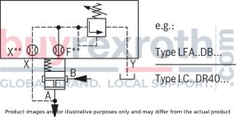
Control cover for 2-way cartridge valves, reliable limiting of the pressure in connection with a 2-way cartridge valve according to the hydraulic symbol.
Unpacked Weight: 9.440 kg
General
2-way cartridge valves for pressure functions are pilot-operated valves in seat or spool design. The power section designed as cartridge valve (1) is installed into a receiving hole standardized according to DIN ISO 7368 and closed with a control cover (2).
The pilot control valve (4) for manual or electrically proportional pressure adjustment is integrated into the control cover (2) or is installed on the control cover (2) as pilot valve with mounting dimensions according to DIN 24 340.
By combination of cartridge valves with the control covers, different pressure functions can be realized. .
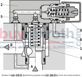
Pressure relief function
The cartridge valve (1) for the pressure relief function (type LC . DB...) is designed as seat valve without area difference (no effective area at port B). The effective pressure at port A is directed via the pilot oil supply orifice (5) to the spring side (6) of the element. Under the pressure set at the pilot control valve (4), the spool (3) is pressure-compensated and closed by the spring force.
On reaching the set pressure, the spool (3) is opened and the pressure at port A is limited according to the pressure-flow characteristics.
Pressure reducing function
Rest position open
The cartridge valve for the pressure reducing function is designed as spool valve without area difference (no effective areas at port B).
As pilot control valve, identical cover types as for the pressure relief function are applied (type LFA..DB...).
The effective pressure at port A is directed via the pilot oil supply orifice to the spring side of the spool. Under the performance limit and the pressure set at the pilot control valve, the spool is pressure-compensated and retained in open position by the spring force to enable free flow from port B to port A.
On reaching the set pressure, the spool is closed and the pressure at port A is reduced according to the pressure-flow characteristics.
|
Size |
Pilot control valve |
manual pressure adjustment |
|||||
|
16 to 32 |
40 to 63 |
80 and 100 |
|||||
|
• |
• |
• |
with directional valve |
||||
|
• = available |
Position "a" |
Position "b" |
|||||
|
Position "a" |
Position "0" |
Position "b" |
|||||
|
Directional valve unloading |
• |
• |
3WE6B9-... |
open |
DB function |
||
|
• |
M-3SE.6C... |
||||||
|
• |
• |
4WE6D... |
DB function |
open |
|||
|
• |
M-3SE.6U... |
||||||
|
• |
3WE10B9-... |
open |
DB function |
||||
|
• |
4WE10D... |
DB function |
open |
||||
|
open |
Circulation circuit |
|
blocked |
Cartridge valve is hydraulically blocked |
|
DB function |
Pressure relief function |
| Data Sheet | Download Data Sheet |
| Manual | Download Manual |
| Manual | Download Manual |
| Manual | Download Manual |
| Max. pressure | 400 |
| Type of connection | Subplate mounting |
| Size | 50 |
| Type of actuation | manual pressure adjustment |
| Hydraulic fluid | HL,HLP,HLPD,HVLP,HVLPD,HFC |
| Seals | NBR |
| Productgroup ID | 9,10,11,12,13,14 |
| Weight | 9.440 |
|
Orifice symbol |
Symbol in ordering code |
|||
|
A** |

|
A** |

|
This orifice is designed as screw-type orifice. If an orifice is to be installed, the respective code letter with the orifice Ø in 1/10 mm has to be entered in the type designation. Example: A12 = Orifice with Ø1.2 mm in channel A. |
|
Ø1,2 |

|

|
This orifice is designed as bore. No specifications are made in the type designation. (Orifice Ø in mm) |
|
|
Z12 |

|

|
This orifice is designed as screw-type orifice. This is a standard orifice. No specifications are made in the type designation. (Orifice Ø in 1/10 mm) |
|
|
Pilot control valve |
Control cover |
Maximum operating pressure in bar Y, T |
included in type |
separate order |
|||
|
Type |
Catalog sheet no. |
NG |
|||||
|
X |
at pressure control |
static |
|||||
|
DBD. 2 K2X/… 1) |
upon request |
16 to 32 |
420 |
depressurized (up to ≈ 2 bar) |
315 |
● |
|
|
DBD. 6 K1X/… 2) |
25 402 |
40 to 63 |
400 |
315 |
● |
||
|
DBD. 10 K1X/… 2) |
25 402 |
80, 100 |
400 |
315 |
● |
||
|
.WE 6 … |
23 178 |
16 to 63 |
350 |
[si]210 (=); 160 (~)[/si][/imp]3050 (=); 2300 (~)[/imp] |
● |
||
|
.WE 10 … |
23 327 |
80, 100 |
315 |
[si]210 (=); 160 (~)[/si][/imp]3050 (=); 2300 (~)[/imp] |
● |
||
|
M-3SEW 6 … |
22 058 |
16 to 63 |
420 |
100 |
● |
||
|
M-3SED 6 … |
22 049 |
16 to 63 |
315 |
X-40 |
● |
||
|
M-3SEW 10 … |
22 075 |
80, 100 |
420 |
100 |
● |
||
|
M-3SED 10 … |
22 045 |
80, 100 |
315 |
X-40 |
● |
||
|
Type |
||
|
01 |
Control cover LFA |
LFA |
|
Size |
||
|
02 |
NG 16 |
16 |
|
NG 25 |
25 |
|
|
NG 32 |
63 |
|
|
NG 40 |
40 |
|
|
NG 50 |
50 |
|
|
NG 63 |
63 |
|
|
NG 80 |
80 |
|
|
NG 100 |
100 |
|
|
Version |
||
|
03 |
With manual pressure adjustment, for electric unloading circuit |
DBW 1) |
|
Adjustment type for pressure adjustment |
||
|
04 |
Rotary knob |
1 |
|
Sleeve with hexagon and protective cap |
2 |
|
|
Lockable rotary knob with scale (H-locking according to automotive standard) |
3 |
|
|
Rotary knob with scale |
4 |
|
|
Component series |
||
|
05 |
Component series 70 ... 79 (70 ... 79: unchanged installation and connection dimensions) 2) |
7X |
|
Component series 60 … 69 (60 … 69: unchanged installation and connection dimensions) 3) |
6X |
|
|
Pressure rating (observe admissible pressure of the pilot control valve) |
||
|
06 |
Set pressure up to 25 bar |
025 |
|
Set pressure up to 50 bar |
050 |
|
|
Set pressure up to 100 bar |
100 |
|
|
Set pressure up to 200 bar |
200 |
|
|
Set pressure up to 315 bar |
315 |
|
|
Set pressure up to 400 bar |
400 |
|
|
Set pressure up to 420 bar |
420 |
|
|
Seal material |
||
|
07 |
NBR seals |
no code |
|
FKM seals |
V |
|
|
01 |
02 |
03 |
04 |
05 |
06 |
07 |
||
|
LFA |
DBW |
‒ |
/ |
Notice:
By combination of a 2-way cartridge valve with a pilot control valve, various valve functions can be realized.
In particular, the following devices come into question in porting pattern form A6 (up to NG 63) and form A10 (NG 80 to 100) DIN 24 340.
Valve mounting screws are included in the scope of delivery of the control cover.
General information on the ordering codes for control covers: Pilot control valves (maximum operating pressure)
Additional preferred types and standard units are specified in the EPS (standard price list).
general
|
Size |
16 | 25 | 32 | 40 | 50 | 63 | 80 | 100 |
hydraulic
|
Size |
16 | 25 | 32 | 40 | 50 | 63 | 80 | 100 | ||
|
Maximum operating pressure 1) |
bar |
420 | ||||||||
|
Hydraulic fluid |
see table | |||||||||
|
Hydraulic fluid temperature range |
NBR seals |
°C |
-30 … +80 | |||||||
|
FKM seals |
°C |
-20 … +80 | ||||||||
|
Viscosity range |
mm²/s |
2.8 … 380 | ||||||||
|
Maximum admissible degree of contamination of the hydraulic fluid 2) |
Class 20/18/15 according to ISO 4406 (c) | |||||||||
| 1) | Attention: Observe pmax of the pilot control valves! |
| 2) | The cleanliness classes specified for the components must be adhered to in hydraulic systems. Effective filtration prevents faults and simultaneously increases the life cycle of the components. For the selection of the filters, see www.boschrexroth.com/filter. |
|
Hydraulic fluid |
Classification |
Suitable sealing materials |
Standards |
|
|
Mineral oil |
HL, HLP |
FKM, NBR |
DIN 51524 |
|
|
Bio-degradable |
Insoluble in water |
HEES (synthetic esters) |
FKM |
VDMA 24568 |
|
HETG (rape seed oil) |
FKM, NBR |
|||
|
Soluble in water |
HEPG (polyglycols) |
FKM |
VDMA 24568 |
|
|
Other hydraulic fluids on request |
||||
For applications outside these parameters, please consult us!
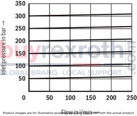
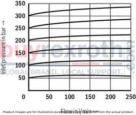
(measured with HLP46, ϑOil = 40 ±5 °C)
The characteristic curves were measured with external, depressurized pilot oil return. Due to the internal pilot oil return, the inlet pressure increases by the output pressure present in port B.
manual pressure adjustment
Type LC 16 DB.E… (with seat piston)

manual pressure adjustment
Type LC 16 DB.E… (with seat piston)
manual pressure adjustment
Type LC 16 DB.D… (seat-spool valve)

manual pressure adjustment
Type LC 16 DB.D… (seat-spool valve)
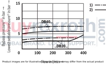
(measured with HLP46, ϑOil = 40 ±5 °C)
The characteristic curves were measured with external, depressurized pilot oil return. Due to the internal pilot oil return, the inlet pressure increases by the output pressure present in port B.
manual pressure adjustment
Type LC 25 DB.E… (with seat piston)
manual pressure adjustment
Type LC 25 DB.E… (with seat piston)

manual pressure adjustment
Type LC 25 DB.D… (with seat-spool piston)

manual pressure adjustment
Type LC 25 DB.D… (with seat-spool piston)

(measured with HLP46, ϑOil = 40 ±5 °C)
The characteristic curves were measured with external, depressurized pilot oil return. Due to the internal pilot oil return, the inlet pressure increases by the output pressure present in port B.
manual pressure adjustment
Type LC 32 DB.E… (with seat piston)

manual pressure adjustment
Type LC 32 DB.E… (with seat piston)

manual pressure adjustment
Type LC 32 DB.D… (with seat-spool piston)

manual pressure adjustment
Type LC 32 DB.D… (with seat-spool piston)
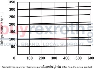
(measured with HLP46, ϑOil = 40 ±5 °C)
The characteristic curves were measured with external, depressurized pilot oil return. Due to the internal pilot oil return, the inlet pressure increases by the output pressure present in port B.
manual pressure adjustment
Type LC 40 DB.E… (with seat piston)

manual pressure adjustment
Type LC 40 DB.E… (with seat piston)
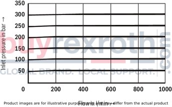
manual pressure adjustment
Type LC 40 DB.D… (with seat-spool piston)

manual pressure adjustment
Type LC 40 DB.D… (with seat-spool piston)

(measured with HLP46, ϑOil = 40 ±5 °C)
The characteristic curves were measured with external, depressurized pilot oil return. Due to the internal pilot oil return, the inlet pressure increases by the output pressure present in port B.
manual pressure adjustment
Type LC 50 DB.E… (with seat piston)

manual pressure adjustment
Type LC 50 DB.E… (with seat piston)

manual pressure adjustment
Type LC 50 DB.D… (with seat-spool piston)

manual pressure adjustment
Type LC 50 DB.D… (with seat-spool piston)

(measured with HLP46, ϑOil = 40 ±5 °C)
The characteristic curves were measured with external, depressurized pilot oil return. Due to the internal pilot oil return, the inlet pressure increases by the output pressure present in port B.
manual pressure adjustment
Type LC 63 DB.E… (with seat piston)
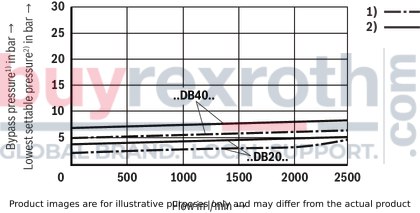
manual pressure adjustment
Type LC 63 DB.E… (with seat piston)

manual pressure adjustment
Type LC 63 DB.D… (with seat-spool piston)

manual pressure adjustment
Type LC 63 DB.D… (with seat-spool piston)
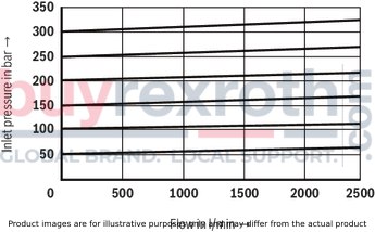
The control covers are equipped with standard orifice fitting – optimized in our test area. Orifice specification in the type key is not necessary. Deviating operating conditions may require respective adjustment of the orifice size. The orifices are designed as screw-type orifices.
Orifice representation in symbol

LFA..DBW.-7X/...NG 16, 25, 32
4WE 6 D../..
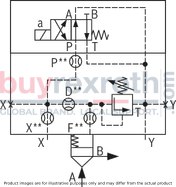
3WE 6 B9-../..

M-3SED 6 U../350…
M-3SEW 6 U../420…

M-3SED 6 C../350…

M-3SEW 6 C../420…

LFA..DBW.-7X/... NG 40, 50, 63
4WE 6 D../..
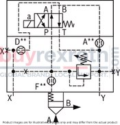
3WE 6 B9-../..

LFA..DBW.-6X/... NG 80, 100
4WE 10 D...
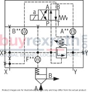
3WE 10 B9...

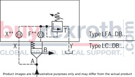
Installation bore and connection dimensions according to ISO 7368
NG16 ... 63
Dimensions in mm
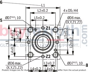
|
5 |
Bore for locating pin (cover pin assembled according to DIN 24 342) |
|
6 |
Information on porting pattern NG 16: Length L1 (axis x–y bores) is 80 mm |
|
8 |
Bore for locating pin at function as main pressure relief valve (reposition cover pin for assembly accordingly) |
NG 80, 100
Dimensions in mm
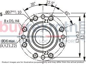
|
5 |
Bore for locating pin (cover pin assembled according to DIN 24 342) |
|
Mounting screws: Hexagon socket head cap screw according to DIN 912-10.9 |
||
|
Pilot control valve Type |
Dimensions |
Tightening torque in Nm |
|
M-3SEW 6 … |
M5 x 45 |
8,9 |
|
M-3SEW 10 … |
M6 x 40 |
15,5 |
|
M-3SED 6 … |
M5 x 50 |
8,9 |
|
M-3SED 10 … |
M6 x 40 |
15,5 |
|
.WE 6 … |
M5 x 50 |
8,9 |
|
.WE 10 … |
M6 x 40 |
15,5 |
|
Mounting screws (included in scope of delivery) |
|||
|
Hexagon socket head cap screw according to DIN 912-10.9 |
|||
|
NG |
Quantity |
Dimensions |
Tightening torque in Nm |
|
16 |
4 |
M 8 x 45 |
32 |
|
25 |
4 |
M 12 x 50 |
110 |
|
32 |
4 |
M 16 x 60 |
270 |
|
40 |
4 |
M 20 x 70 |
520 |
|
50 |
4 |
M 20 x 80 |
520 |
|
63 |
4 |
M 30 x 100 |
1800 |
|
80 |
8 |
M 24 x 120 |
900 |
|
100 |
8 |
M 30 x 120 |
1800 |
|
Thread dimensions of orifice |
|||
|
D orifices at type ..DBE.. NG 25 to 63 |
M8 x 1 conical |
||
|
Orifices for NG 80, 100 |
M8 x 1 conical (A**, B**, P**, D**) or G 1/4 (X**, F**) |
||
|
other installed orifices |
M6 conical |
||
NG 16, 25, 32
Dimensions in mm

|
1 |
Port X optionally as threaded port |
|
2 |
Port Y optionally as threaded port |
|
3 |
Locating pin |
|
4 |
Adjustment type "2" |
|
5 |
Adjustment type "1" |
|
6 |
Adjustment type "3" |
|
7 |
Adjustment type "4" |
|
8 |
Space required to remove the key |
|
9 |
Name plate |
|
10 |
Lock nut |
|
11 |
Valve mounting screws are included in the scope of delivery of the control cover |
NG 40, 50
Dimensions in mm
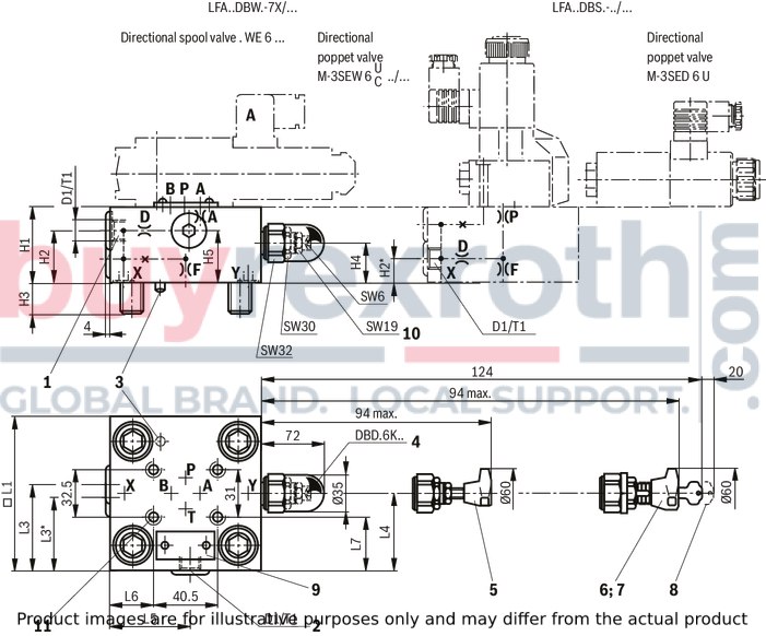
|
1 |
Port X optionally as threaded port |
|
2 |
Port Y optionally as threaded port |
|
3 |
Locating pin |
|
4 |
Adjustment type "2" |
|
5 |
Adjustment type "1" |
|
6 |
Adjustment type "3" |
|
7 |
Adjustment type "4" |
|
8 |
Space required to remove the key |
|
9 |
Name plate |
|
10 |
Lock nut |
|
11 |
Valve mounting screws are included in the scope of delivery of the control cover |
NG63
Dimensions in mm
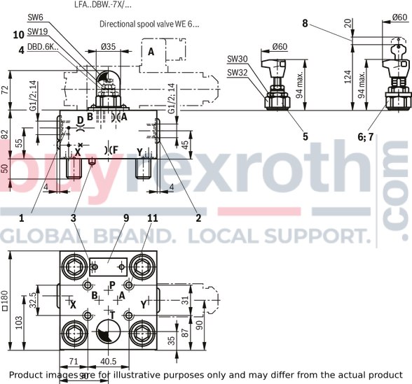
|
1 |
Port X optionally as threaded port |
|
2 |
Port Y optionally as threaded port |
|
3 |
Locating pin |
|
4 |
Adjustment type "2" |
|
5 |
Adjustment type "1" |
|
6 |
Adjustment type "3" |
|
7 |
Adjustment type "4" |
|
8 |
Space required to remove the key |
|
9 |
Name plate |
|
10 |
Lock nut |
|
11 |
Valve mounting screws are included in the scope of delivery of the control cover |
NG 80, 100
Dimensions in mm
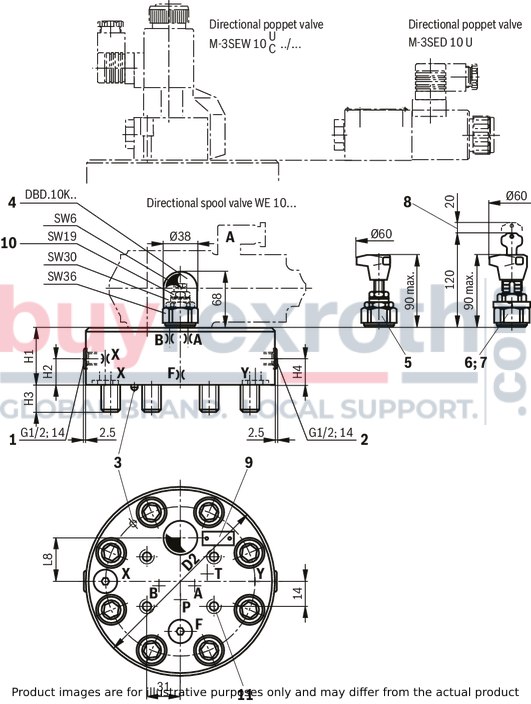
|
NG |
ØD1H7 |
ØD2 |
ØD3/(ØD3*) 1) |
ØD4H7 |
ØD5 2) |
ØD6 |
ØD7H13 |
H1 |
H2 |
H3 |
H4 |
H5 |
H6 |
H7 |
H8 |
H9 |
L1 |
L2 |
L3 |
L4 |
L5 |
W |
Ro 3) |
Ru 3) |
||
|
mm |
mm |
mm |
mm |
mm |
mm |
mm |
mm |
mm |
mm |
mm |
mm |
mm |
mm |
mm |
mm |
mm |
mm |
mm |
mm |
mm |
mm |
mm |
mm |
mm |
||
| 16 | 32 | 16 |
16 25 |
25 | M8 | 4 | 4 | 42.5 | 56 | + 0.1 | 43 | + 0.2 | 20 | 11 | 2 | 20 | 2 | 0.5 |
65 80 |
46 | 23 | 25 | 10.5 | 0.05 | 2 | 1 |
| 25 | 45 | 25 |
25 32 |
34 | M12 | 6 | 6 | 57 | 72 | + 0.1 | 58 | + 0.2 | 25 | 12 | 2.5 | 30 | 2.5 | 1 | 85 | 58 | 29 | 33 | 16 | 0.05 | 2 | 1 |
| 32 | 60 | 32 |
32 40 |
45 | M16 | 8 | 6 | 68.5 | 85 | + 0.1 | 70 | + 0.2 | 35 | 13 | 2.5 | 30 | 2.5 | 1.5 | 102 | 70 | 35 | 41 | 17 | 0.1 | 2 | 1 |
| 40 | 75 | 40 |
40 50 |
55 | M20 | 10 | 6 | 84.5 | 105 | + 0.1 | 87 | + 0.3 | 45 | 15 | 3 | 30 | 3 | 2.5 | 125 | 85 | 42.5 | 50 | 23 | 0.1 | 4 | 1 |
| 50 | 90 | 50 |
50 63 |
68 | M20 | 10 | 8 | 97.5 | 122 | + 0.1 | 100 | + 0.3 | 45 | 17 | 3 | 35 | 4 | 2.5 | 140 | 100 | 50 | 58 | 30 | 0.1 | 4 | 1 |
| 63 | 120 | 63 |
63 80 |
90 | M30 | 12 | 8 | 127 | 155 | + 0.1 | 130 | + 0.3 | 65 | 20 | 4 | 40 | 4 | 3 | 180 | 125 | 62.5 | 75 | 38 | 0.1 | 4 | 1 |
| 80 | 145 | 80 |
80 100 |
110 | M24 | 16 | 10 | 170.5 | 205 | + 0.1 | 175 | + 0.4 | 50 | 25 | 5 | 40 | 5 | 4.5 | 250 | 200 | - | - | - | 0.1 | 4 | 1 |
| 100 | 180 | 100 |
100 125 |
135 | M30 | 20 | 10 | 205.5 | 245 | + 0.1 | 210 | + 0.4 | 63 | 29 | 5 | 50 | 5 | 4.5 | 300 | 245 | - | - | - | 0.1 | 4 | 1 |
| 16 | 32 | 16 |
16 25 |
25 | M8 | 4 | 4 | 42.5 | 56 | + 0.1 | 43 | + 0.2 | 20 | 11 | 2 | 20 | 2 | 0.5 | 65 | 46 | 23 | 25 | 10.5 | 0.05 | 2 | 1 |
| 25 | 45 | 25 |
25 32 |
34 | M12 | 6 | 6 | 57 | 72 | + 0.1 | 58 | + 0.2 | 25 | 12 | 2.5 | 30 | 2.5 | 1 | 85 | 58 | 29 | 33 | 16 | 0.05 | 2 | 1 |
| 32 | 60 | 32 |
32 40 |
45 | M16 | 8 | 6 | 68.5 | 85 | + 0.1 | 70 | + 0.2 | 35 | 13 | 2.5 | 30 | 2.5 | 1.5 | 102 | 70 | 35 | 41 | 17 | 0.1 | 2 | 1 |
| 40 | 75 | 40 |
40 50 |
55 | M20 | 10 | 6 | 84.5 | 105 | + 0.1 | 87 | + 0.3 | 45 | 15 | 3 | 30 | 3 | 2.5 | 125 | 85 | 42.5 | 50 | 23 | 0.1 | 4 | 1 |
| 50 | 90 | 50 |
50 63 |
68 | M20 | 10 | 8 | 97.5 | 122 | + 0.1 | 100 | + 0.3 | 45 | 17 | 3 | 35 | 4 | 2.5 | 140 | 100 | 50 | 58 | 30 | 0.1 | 4 | 1 |
| 63 | 120 | 63 |
63 80 |
90 | M30 | 12 | 8 | 127 | 155 | + 0.1 | 130 | + 0.3 | 65 | 20 | 4 | 40 | 4 | 3 | 180 | 125 | 62.5 | 75 | 38 | 0.1 | 4 | 1 |
| 80 | 145 | 80 |
80 100 |
110 | M24 | 16 | 10 | 170.5 | 205 | + 0.1 | 175 | + 0.4 | 50 | 25 | 5 | 40 | 5 | 4.5 | 250 | 200 | - | - | - | 0.1 | 4 | 1 |
| 100 | 180 | 100 |
100 125 |
135 | M30 | 20 | 10 | 205.5 | 245 | + 0.1 | 210 | + 0.4 | 63 | 29 | 5 | 50 | 5 | 4.5 | 300 | 245 | - | - | - | 0.1 | 4 | 1 |
| 1) | Due to the use of a bore with ØD3*, port B protrudes over the upper limit of the area intended in ISO 7368. This is, however, possible due to the sealing concept and reduces the pressure loss during flow through the valve. Thus, we recommend a bore with ØD3*. |
| 2) | Mounting thread for version "/12" see data sheet 08936 |
| 3) | Maximum dimension |
Notice:
The dimensions are nominal dimensions which are subject to tolerances.
|
NG |
Ø Orifice P** 1) |
Ø Orifice X** 1) |
Ø Orifice F** 1) |
Ø Orifice D** 1) |
H1 |
H2 |
H3 |
H4 |
H5 |
L1 |
L2 |
L3 |
L4 |
L5 |
L7 |
|
mm |
mm |
mm |
mm |
mm |
mm |
mm |
mm |
mm |
mm |
mm |
mm |
mm |
mm |
mm |
|
| 16 | 1 | 0.8 | 1 | 0.8 | 40 | 17 | 15 | 19 | 28 | 65 | 80 | 36.5 | 32.5 | 35 | 17 |
| 25 | 1 | 0.8 | 1 | 0.8 | 40 | 19 | 24 | 19 | 28 | 85 | 85 | 49 | 45.5 | 36 | 27 |
| 32 | 1 | 1 | 1.2 | 1 | 50 | 26 | 28 | 26 | 37 | 100 | 100 | 56.5 | 53 | 57 | 34.5 |
| 1) | Orifice Ø, orifice M6 conical |
|
NG |
Ø Orifice A** 1) |
Ø Orifice P** 1) |
Ø Orifice F** 1) |
Ø Orifice D** 1) |
D1 |
H1 |
H2 |
H3 |
H4 |
H5 |
▢ L1 |
L3 |
L4 |
L5 |
L7 |
T1 |
|
mm |
mm |
mm |
mm |
mm |
mm |
mm |
mm |
mm |
mm |
mm |
mm |
mm |
mm |
mm |
||
| 40 | 0.8 | 1.2 | 1.2 | 1 | G1/4 | 60 | 46 | 32 | 27 | 40 | 125 | 62.5 | 76 | 68 | 47 | 12 |
| 50 | 0.8 | 1.5 | 1.5 | 2 | G1/2 | 68 | 51 | 34 | 35 | 50 | 140 | 67.5 | 84 | 74.5 | 54.5 | 14 |
| 1) | Orifice Ø, orifice M6 conical |
|
NG |
Ø Orifice A** 1) |
Ø Orifice F** 1) |
Ø Orifice D** 1) |
|
mm |
mm |
mm |
|
| 63 | 1 | 2 | 2.5 |
| 1) | Orifice Ø, orifice M6 conical |
|
NG |
Ø Orifice A** 1) |
Ø Orifice B** 1) |
Ø Orifice P** 1) |
Ø Orifice X** 2) |
Ø Orifice F** 2) |
D2 |
H1 |
H2 |
H3 |
H4 |
L8 |
|
mm |
mm |
mm |
mm |
mm |
mm |
mm |
mm |
mm |
mm |
mm |
|
| 80 | 1.2 | 3 | 3.5 | 3 | 2.5 | 250 | 100 | 30 | 45 | 52 | 75 |
| 100 | 1.5 | 3 | 3.5 | 3 | 2.5 | 300 | 100 | 30 | 51 | 52 | 85 |
| 1) | Orifice Ø, orifice M8 x 1 conical |
| 2) | Orifice Ø, orifice G 1/4 conical |
2/2, 3/2 and 4/2 directional seat valve with solenoid actuation
M-.SED6
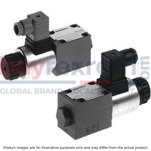
2/2, 3/2 and 4/2 directional seat valve with solenoid actuation
M-.SED6
Size 6 Component series 1X Maximum operating pressure 350 bar Maximum flow 25 l/minData sheet
Operating Instructions
Configurator / CAD
Spare parts & repair
3/2 and 4/2 directional seat valve with solenoid actuation
M-.SED 10
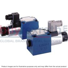
3/2 and 4/2 directional seat valve with solenoid actuation
M-.SED 10
Size 10 Component series 1X Maximum operating pressure 350 bar Maximum flow 40 l/minData sheet
Operating Instructions
Configurator / CAD
Spare parts & repair
Directional poppet valves, directly operated, with solenoid actuation
M-.SEW 6
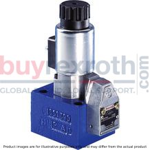
Directional poppet valves, directly operated, with solenoid actuation
M-.SEW 6
Size 6 Component series 3X Maximum operating pressure 420 / 630 bar Maximum flow 25 l/minData sheet
Operating Instructions
Configurator / CAD
Spare parts & repair
3/2 and 4/2 directional seat valve with solenoid actuation
M-.SEW 10
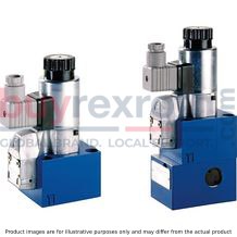
3/2 and 4/2 directional seat valve with solenoid actuation
M-.SEW 10
Size 10 Component series 1X Maximum operating pressure 420 / 630 bar Maximum flow 40 l/minData sheet
Operating Instructions
Configurator / CAD
Spare parts & repair
Directional spool valves, direct operated, with solenoid actuation
WE 6...E
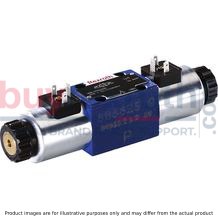
Directional spool valves, direct operated, with solenoid actuation
WE 6...E
Size 6 Component series 6X Maximum operating pressure 350 bar Maximum flow (DC) 80 l/min Maximum flow (AC) 60 l/minData sheet
Configurator / CAD
Spare parts & repair
4/3, 4/2 and 3/2 directional valve with wet-pin DC solenoids
WE 6...E...407
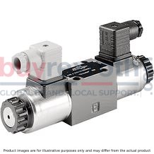
4/3, 4/2 and 3/2 directional valve with wet-pin DC solenoids
WE 6...E...407
Size 6 Component series 6X Maximum operating pressure 315 bar Maximum flow 60 l/minData sheet
Configurator / CAD
General product information on hydraulic products
Installation, commissioning and maintenance of industrial valves
Spare parts & repair
Directional spool valves, direct operated, with solenoid actuation
WE 6...E...UR
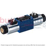
Directional spool valves, direct operated, with solenoid actuation
WE 6...E...UR
Solenoid coil is an approved component with UR-marking according to UL 906 Size 6 Component series 6X Maximum operating pressure 350 bar Maximum flow (DC) 80 l/min Maximum flow (AC) 60 l/minData sheet
Spare parts & repair
Directional spool valves, direct operated, with solenoid actuation
WE 10...C
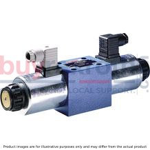
Directional spool valves, direct operated, with solenoid actuation
WE 10...C
Size 10 Component series 3X, 4X Maximum operating pressure 315 bar Maximum flow 120 l/minData sheet
Configurator / CAD
Spare parts & repair
Related Products
R900431167
$574.00 USD
R901236165
$466.00 USD
R901112942
$606.00 USD
R900769596
$417.00 USD
R901182725
$623.00 USD


