


DIRECTIONAL SPOOL VALVE Z4WEH10E63-4X/6EW110N9ETK4/B10V
Manufacturer: Bosch Rexroth
Material #: R901081099
Model : Z4WEH10E63-4X/6EW110N9ETK4/B10V
***Disclaimer: The following summary contains information gathered from various sources such as product descriptions, technical specifications and catalogs. While efforts have been made to provide accurate details, inaccuracies may occur. It is advised to verify all information by contacting Bosch Rexroth directly.***
The Bosch Rexroth Z4WEH10E63-4X/6EW110N9ETK4/B10V (R901081099) is a high-performance directional spool valve that is pilot-operated and designed for electrohydraulic actuation. This valve is adept at functioning as either a shutoff through valve or a shutoff short-circuit through valve, ensuring versatile application in controlling the direction of hydraulic flow. It features free flow in every spool position for ports P and T, enhancing its operational flexibility.
The Z4WEH10E63-4X/6EW110N9ETK4/B10V conforms to the ISO porting pattern, ensuring compatibility with standardized connections and simplifying installation processes. It supports both wet-pin DC or AC solenoids, providing options to suit various electrical system requirements. Additionally, this model offers the possibility of including an auxiliary operating device according to specific user needs.
For electrical connections, users have the choice of individual or central connection configurations. The valve also boasts optional features such as switching time adjustment for precise control over transition times between states, as well as stroke setting adjustments on the main spool to fine-tune operational parameters. To further enhance its capabilities, inductive position switches and proximity sensors can be added for contactless detection of spool position.
This particular model is part of the component series X from Bosch Rexroth and can handle a maximum operating pressure of up to bar units and accommodate a maximum flow rate measured in liters per minute (l/min). These specifications indicate that it's built to withstand demanding conditions while maintaining efficient fluid control within hydraulic systems. The R901081099 is particularly suited for applications requiring robust performance and precise control over hydraulic operations.
$2,667.00 USD
More are expected on October 6, 2026
Note: Sales tax, shipping, and applicable tariffs will be calculated at checkout.Status: This product is temporarily out of stock.
Qty: Delivered as early as October 6, 2026 when ordered in
This product is eligible for factory repair.
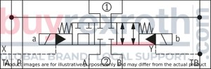
Size 10, symbol E63, with solenoid actuation, 110 VAC 50/60Hz
Industrial hydraulic valve in the medium performance range. Reliable switching of the oil flow direction according to hydraulic symbol
Unpacked Weight: 4.3 kg
Directional spool valve, pilot-operated Type of actuation: electro-hydraulic Functioning as shut-off through valve or shut-off short-circuit through valve P and T free flow in every spool position Porting pattern according to ISO 4401-05-04-0-05 Wet-pin DC or AC solenoids, optional Optional auxiliary operating device Electrical connection as individual or central connection, see RE 23178 Switching time adjustment, optional Stroke setting at main spool, optional Inductive position switch and proximity sensors (contactless)
|
➀ |
component side |
|
➁ |
plate side |
general
|
Size |
10 | ||
|
Weight |
Valve with one solenoid |
kg |
4.2 |
|
Valve with two solenoids |
kg |
4.6 | |
|
Switching time adjustment |
kg |
0.8 | |
|
3-way pressure reducing valve |
kg |
0.4 | |
|
Plate for version "T" |
kg |
0.5 | |
|
Installation position |
any | ||
|
Ambient temperature ranges (NBR seals) |
°C |
-30 … +50 | |
|
Ambient temperature ranges (FKM seals) |
°C |
-20 … +50 | |
hydraulic
|
Size |
10 | |||
|
Maximum operating pressure |
Port P |
External pilot oil supply |
bar |
315 |
|
Internal pilot oil supply (without pressure reducing valve) |
bar |
250 | ||
|
Internal pilot oil supply (with pressure reducing valve) |
bar |
315 | ||
|
Anschluss A |
bar |
315 | ||
|
Port B |
bar |
315 | ||
|
Port T |
with DC solenoid |
bar |
210 | |
|
with AC solenoid |
bar |
160 | ||
|
Maximum flow |
l/min |
160 | ||
|
Minimum pilot pressure |
bar |
12 | ||
|
Pilot volume for switching process |
cm³ |
1.3 | ||
|
Hydraulic fluid 1) |
see table | |||
|
Hydraulic fluid temperature range (NBR seals) |
°C |
-30 … +80 | ||
|
Hydraulic fluid temperature range (FKM seals) |
°C |
-20 … +80 | ||
|
Viscosity range |
mm²/s |
2.8 … 500 | ||
|
Maximum admissible degree of contamination of the hydraulic fluid 2) |
Class 20/18/15 according to ISO 4406 (c) | |||
| 1) | The ignition temperature of the process and operating medium used must be over the maximum solenoid surface temperature. |
| 2) | The cleanliness classes specified for the components must be adhered to in hydraulic systems. Effective filtration prevents faults and simultaneously increases the life cycle of the components. For the selection of the filters, see www.boschrexroth.com/filter. |
|
Hydraulic fluid |
Classification |
Suitable sealing materials |
Standards |
|
|
Mineral oil |
HL, HLP |
NBR, FKM |
DIN 51524 |
|
|
Fast bio-degradable hydraulic fluids |
VDMA 24568 |
|||
|
Environmentally compatible |
Insoluble in water |
HETG |
NBR, FKM |
|
|
HEES |
FKM |
|||
|
Soluble in water |
HEPG |
NBR, FKM |
||
|
Other hydraulic fluids on request |
||||
electrical
|
Switching time according to ISO 6403 |
At pilot pressure |
bar |
70 | 140 | 210 | |||
|
Voltage type |
Direct voltage | AC voltage | Direct voltage | AC voltage | Direct voltage | AC voltage | ||
|
On |
ms |
65 | - | 60 | - | 55 | - | |
|
ms |
- | 30 | - | 25 | - | 20 | ||
|
Off |
ms |
- | 30 | - | 30 | - | 30 | |
|
ms |
30 | - | 30 | - | 30 | - | ||
Notices!
Actuation of the manual override is only possible up to a tank pressure of approx. 50 bar. Avoid damage to the bore of the manual override! (Special tool for the operation, separate order, material no. R900024943). When the manual override is blocked, the actuation of the solenoid must be prevented! The simultaneous actuation of the solenoids must be prevented!Inductive position switch type QM: electrical connection
electrical
|
Connection voltage (DC voltage) |
V |
24 | ||
|
Voltage tolerance (connection voltage) |
+30 %/-15 % | |||
|
Admissible residual ripple |
% |
≤ 10 | ||
|
Max. load capacity |
mA |
400 | ||
|
Switching outputs 
|
PNP transistor outputs, load between switching outputs and GND | |||
|
Pinout 
|
1 |
V |
24 | |
|
2, 4 |
Switching output |
mA |
400 | |
|
3 |
Earthing (GND) |
V |
0 | |
The electric connection is realized via a 4-pole mating connector (separate order) with connection thread M12 x 1.
For applications outside these parameters, please consult us!
(measured with HLP46, ϑOil = 40 ±5 °C)
Δp-qV characteristic curves

E62
Version "ET"

E62
Version "T"
E63
Version "ET"

E63
Version "T"

E68
Version "ET"

E68
Version "T"

E501)
Version "ET"

| 1) | Opening cross-section in spool position "a" (A2 → B2) = 50 mm2 |
E50
Version "T"

| 1) | Opening cross-section in spool position "a" (A2 → B2) = 50 mm2 |
E51
Version "ET"

E51
Version "T"

E521)
Version "ET"

| 1) | Opening cross-section in spool position "b" (A2 → B2) = 35 mm2 |
E52
Version "T"

| 1) | Opening cross-section in spool position "b" (A2 → B2) = 35 mm2 |
|
➀ |
component side |
|
➁ |
plate side |
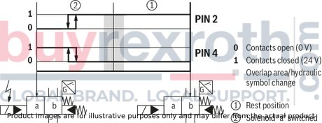
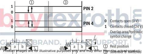
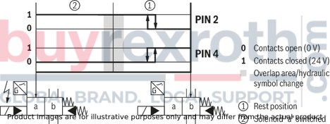
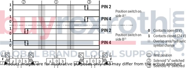
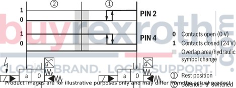
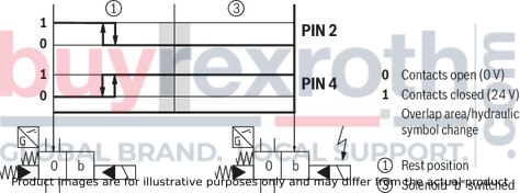
Inductive position switch type QM Switching logics
Version QMA
(Position switch on side B, monitored spool position of the main stage "a")
Version QMA
(Position switch on side B, monitored spool position of the main stage "a")
Version QMB
(Position switch on side A, monitored spool position of the main stage "b")
Version QMB
(Position switch on side A, monitored spool position of the main stage "b")

version QMAB
(Position switch on side A and B, monitored spool position "a" and "b")
Version QM0
(Position switch on side A and B, monitored spool position "0")
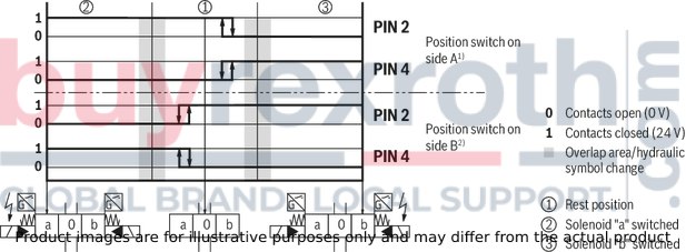
| 1) No signal change at the position switch on side B with spool position "a" | |
| 2) No signal change at the position switch on side A with spool position "b" |
Version QM0
(Position switch on side B, monitored spool position of the main stage "0")
Version QM0
(Position switch on side A, monitored spool position of the main stage "0")
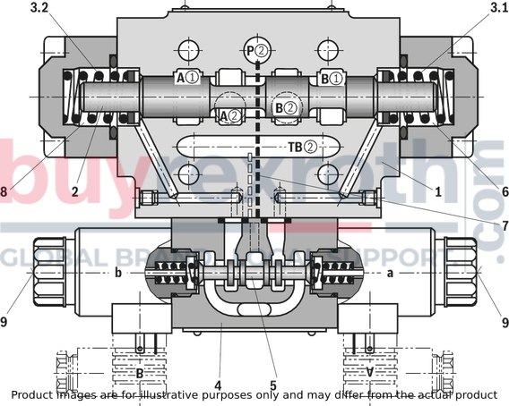
Dimensions in mm
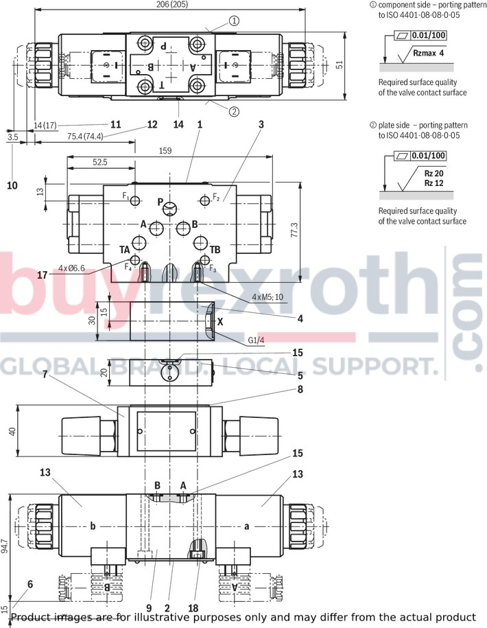
|
1 |
Name plate complete valve |
|
2 |
Name plate pilot control valve |
|
3 |
Main valve |
|
4 |
Sandwich plate for external pilot control (use for operating pressure > 210 bar) |
|
5 |
Pressure reducing valve "D3" (to be used for pilot pressures above 250 bar)Material no.:NBR seals: R900323180FKM seals: R900323664 |
|
6 |
Space required to remove the mating connector |
|
7 |
Switching time adjustment (throttle check valve); dependent on supply or discharge control installation position (representation: supply control) |
|
8 |
R-ring plate |
|
9 |
Pilot control valve- Type 4WE 6 J.. at symbol E62- Type 4WE 6 Y.. at symbol E50, E51, E52, E63, E68Dimensions () for valve with AC solenoid |
|
10 |
Dimension for valve without manual override |
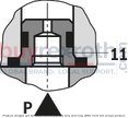
|
11 |
Dimension for valve with manual override "N";Dimensions () for valve with AC solenoid |
|
12 |
Dimension for valve with concealed manual override "N9"; dimensions () for valve with AC solenoid without manual override |
|
13 |
Solenoid "a" and "b" (rotatable by 90°) |
|
14 |
Identical seal rings for ports A, B, P, TA and TB |
|
15 |
Identical seal rings for ports A, B, P and T |
|
17 |
Valve mounting bores Valve mounting screws (separate order) 4 hexagon socket head cap screws ISO 4762 - M6 - 10.9 |
|
18 |
Valve mounting screws (separate order)4 hexagon socket head cap screws ISO 4762 - M5 - 10.9 |
Notice!
Length and tightening torque of the valve mounting screws must be calculated according to the components mounted.

|
Mounting options |
L1 |
L2 |
|
mm |
mm |
|
| Stroke setting on side A and B | 95 | 149 |
| Stroke setting on side A | 95 | - |
| Stroke setting on side B | - | 149 |
Stroke setting, mounting options
The stroke of the main spool is limited by the stroke setting.
The piston stroke is shortened by untightening the lock nut (17) and clockwise rotation of the adjustment spindle (18). For this, the control chamber has to be depressurized.
Stroke 6 mm (1 rotation = 1 mm stroke)
|
17 |
Lock nut SW27 |
|
18 |
Adjustment spindle, internal hexagon SW5 |
Spool position monitoring
Notice:
The dimensions are nominal dimensions which are subject to tolerances.
Dimensions in mm

Inductive position switch type QM
Type Z4WEH 10
Dimensions in mm

|
Mounting options: |
||||
|
Monitored spool position |
Ordering code |
Position switch on side |
||
|
„a“ |
„b“ |
"a" and "b" |
||
|
„a“ |
QMAG24 |
X |
||
|
„b“ |
QMBG24 |
X |
||
|
"a" and "b" |
QMABG24 |
X |
||
Stroke setting, mounting options
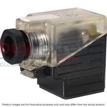
Mating connectors for valves with connector “K4”, without circuitry, standard
3P Z4

Mating connectors for valves with connector “K4”, without circuitry, standard
3P Z4
For valves with connector “K4” according to EN 175301-803 and ISO 4400, 2-pole + PE, “large cubic connector” Mating connectors for valves with one or two solenoids (individual connection)Data sheet
Spare parts & repair
Mating connectors for valves with connector “K4”, with indicator light
3P Z5L
Mating connectors for valves with connector “K4”, with indicator light
3P Z5L
For valves with connector “K4” according to EN 175301-803 and ISO 4400, 2-pole + PE, “large cubic connector” Mating connectors for valves with one or two solenoids (individual connection)Data sheet
Spare parts & repair
Mating connectors for valves with connector “K4”, with indicator light and Zener diode suppression circuit
3P Z5L1
Mating connectors for valves with connector “K4”, with indicator light and Zener diode suppression circuit
3P Z5L1
For valves with connector “K4” according to EN 175301-803 and ISO 4400, 2-pole + PE, “large cubic connector” Mating connectors for valves with one or two solenoids (individual connection)Data sheet
Spare parts & repair
Mating connectors for valves with connector “K4”, with rectifier
3P RZ5
Mating connectors for valves with connector “K4”, with rectifier
3P RZ5
For valves with connector “K4” according to EN 175301-803 and ISO 4400, 2-pole + PE, “large cubic connector” Mating connectors for valves with one or two solenoids (individual connection)Data sheet
Spare parts & repair
Related Products
R900963573
$3,169.00 USD
R901081099
$2,667.00 USD
R901307032
$2,834.00 USD
R901048863
$5,115.00 USD
R901365483
$2,448.00 USD


