***Disclaimer: The following summary contains information gathered from various sources such as product descriptions, technical specifications and catalogs. While efforts have been made to provide accurate details, inaccuracies may occur. It is advised to verify all information by contacting Bosch Rexroth directly.***
The Bosch Rexroth DAW20B2-5X/100-17-6EW110N9K4 (R901035097) is a highly sophisticated pilot-operated pressure cutoff valve, designed to ensure efficient control in hydraulic systems, particularly suited for accumulator charging circuits. This valve operates by filling an accumulator until a preset charging pressure is reached, then switching the flow to depressurized circulation until the system pressure drops by a specified differential, triggering the recharging process.
The DAW20B2-5X/100-17-6EW110N9K4 features a main housing, a pilot control valve, a main spool insert, and an integrated check valve that facilitates the switch of pump flow from P to B and P to T. The intricacies of its operation involve various components such as nozzle orifices and control lines that contribute to maintaining system pressure and ensuring smooth transitions between charging and depressurization cycles.
This model is distinguished by its ability to dampen switching shocks through the strategic placement of its nozzle in the control line, which helps manage circulation pressure from P to T. Additionally, while it does not directly limit pump pressure but does so indirectly through other components like the check valve and pilot control valve.
The DAW20B2-5X/100-17-6EW110N9K4 allows for adjustable switching pressure differentials with factory settings typically around nominal pressures. Adjustments can be secured using a clamping screw and lock nut for consistent performance. It is crucial that system designers ensure proper sizing and layout of additional required components such as actuator A, pump P, tank T connections, control lines, and check valves to prevent blockages and maintain flow characteristics in line with specified curves.
This model boasts compatibility with various adjustment types for subplate mounting or as a cartridge valve. With options like rotary knobs or lockable rotary knobs with scales, it provides versatility for precise adjustments according to user requirements. Additionally, solenoid-operated unloading through built-on directional spool valves adds another layer of operational flexibility. The DAW20B2-5X/100-17-6EW110N9K4 can handle maximum operating pressures up to bar levels and accommodate maximum flow rates measured in liters per minute (l/min).
$2,848.00 USD
More are expected on August 27, 2026
| Qty | Price | Savings |
|---|---|---|
| 5-24 | $2,776.80 USD | $71.20 USD |
| 25+ | $2,705.60 USD | $142.40 USD |
Status: This product is temporarily out of stock.
Qty: Delivered as early as August 27, 2026 when ordered in
This product is eligible for factory repair.
For subplate mounting As cartridge valve 4 adjustment types, optionally:
• Rotary knob
• Adjustment spindle with protective cap
• Lockable rotary knob with scale
• Rotary knob with scale 4 pressure ratings Solenoid-operated unloading via built-on directional spool valve
Type DAW…FS… (freely adjustable switching pressure differential)
The pressure valve type DAW is a pilot-operated pressure cut-off valve. For example, it is used in accumulator charging circuits. Here, an accumulator is filled until the accumulator charging pressure is reached. After reaching the accumulator pressure, the valve switches the flow to depressurized circulation until the pressure in the hydraulic system has fallen by the switching pressure differential. Afterwards, the charging process is started again.
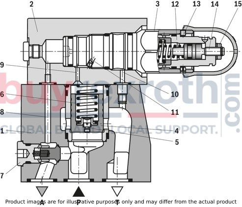
The pressure cut-off valve generally consists of main housing (1), pilot control valve (2 and 3), main spool insert (4) and check valve (7).
Switching of the pump flow from P to B to P to T.The pump delivers via the check valve (7) into the hydraulic system (P to A). The pressure applied in channel A acts via the control line (8) on the control spool in the pilot control valve (3). Simultaneously, the pressure in channel P is applied via nozzle (5) to the spring-loaded side of the main spool (4) and via the control line (9) and at the inlet (11) of the screw-in cartridge valve (3). As soon as the top cut-off pressure set at the screw-in cartridge valve (3) by means of the adjustment spindle (12) is reached in the hydraulic system, the screw-in cartridge valve opens the connection from the spring-loaded side of the main spool (4) to the return line (10) to T internally (type DAW ...) or externally via port Y (type DAW ...Y).
Due to the nozzle (5), a pressure drop occurs at the main spool (4). It is lifted from the seat and opens connection P to T. The check valve (7) closes the connection from P to A. The actuator pressure A holds the screw-in cartridge valve (3) in open position.
Switching of the pump flow from P to T to P to A.If the actuator pressure A has fallen to the pressure value set at the adjustment spindle (14), the screw-in cartridge valve (3) switches to initial position and closes the connection from the spring-loaded side of the main spool (4) to the return line (10). This way, the pressure on the spring-loaded side of the main spool (4) is increased and the connection from P to T is closed by the compression spring (6). The pump again delivers via the check valve (7) into the hydraulic system from P to A.
Version "FSB07"
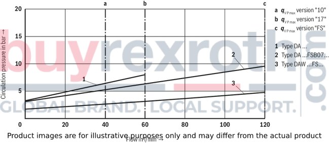
The nozzle of this valve is located in the control line (11) for potential switching shock damping. This way, the circulation pressure (P to T) is increased. See characteristic curves.
Notices!
Only indirect pressure limiting function:A pressure limiting function of the pump pressure (to the tank) is not directly provided but only indirectly via the check valve (7), control line (8) and pilot control valve (2) to channel T.
Setting the switching pressure differentialAt the factory, the valves are set at nominal pressure to a switching pressure differential of approx. 10 % to 12 %. A setting of 50 % of the nominal pressure is possible.
On delivery, the adjustment spindle (12) is screwed out and set to the minimum adjustable switching pressure.
By screwing in the adjustment spindle (12), the top switching pressure may be increased.
The switching pressure differential is adjusted via the adjustment spindle (14): Screw out to reduce, screw in to increase.
The pressure adjustments are secured via the clamping screw (13) and lock nut (15).
Different system conditions (particularly high pump and actuator flows) may lead to higher switching pressures than indicated in the characteristic curves. Here, the valve offers the possibility of optional adjustment of the switching pressure differential to the system.Type DA 10 -2-5X/.FS…
Type DAW… (fixed switching pressure differential 10 % or 17 %)
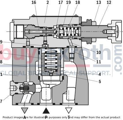
The function of this valve complies with the function of version "FS". At the pilot control valve, however, only the top switching pressure and not the switching pressure differential can be set.
The pilot spool surface (16) exceeds the effective ball (17) surface optionally by 10 % or 17 %.
This way, the effective force at the pilot spool (16) exceeds the effective force at the ball (17) by 10 % or 17%.
Switching of the pump flow from P to B to P to T.The pressure in channel P is applied via nozzles (5) and (9) to the spring-loaded side of the main spool (4) and at ball (17) in the pilot control valve (2). As soon as the cut-off pressure set at the adjustment spindle (12) is reached in the hydraulic system, the ball (17) opens against the spring (18). The hydraulic fluid now flows via nozzles (5) and (9) into the spring chamber (19) to the return line (10) to T (type DAW ...) or externally via port Y (type DAW ...Y). The main spool (4) is lifted from the seat and opens connection P to T. The check valve (7) closes the connection from P to A. Via the pilot spool (16), the actuator pressure A holds the ball in the pilot control valve (2) in open position.
Switching of the pump flow from P to T to P to A.If the actuator pressure A drops by the switching pressure differential range of 10 % or 17 % in comparison with the set cut-off pressure (according to characteristic curves on page 11), the spring (18) closes the ball (17) in the pilot control valve (2). This way, the pressure on the spring-loaded side of the main spool (4) is increased and the connection from P to T is closed by the compression spring (6). The pump again delivers via the check valve (7) into the hydraulic system from P to A.
Type DA 10 -1-5X/…
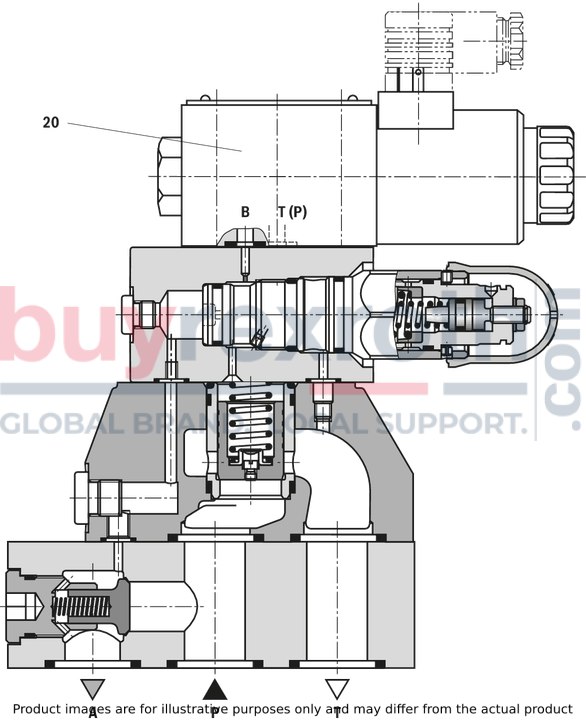
The function of this valve complies with the function of valve type DAW …. However, switching can be realized as required from P to T or from P to A by means of solenoid-actuated directional spool valve (20) for pressure below the set cut-off pressure.
Type DAW 20 -1-5X/…6E..K4…
Type DAWC…
Pressure cut-off valve type DAWC 30 …FS…
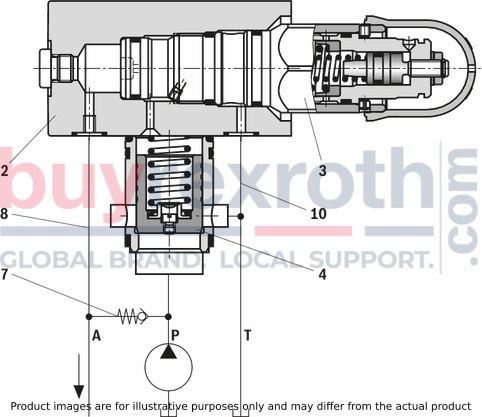
This valve consists of pilot control housing (2), screw-in cartridge valve (3) as pilot control element and a main spool insert (4).
Pressure cut-off valve type DAWC …10/17...
This valve consists of pilot control valve (2) and an optional main spool insert (4).
Notice for circuit design with type DAC...
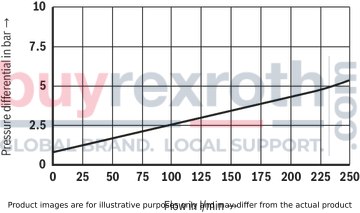
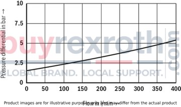
The ports required for actuator (A), pump (P) and tank (T), the required control lines (8) and (10) as well as the required check valve (7) are not included in the scope of delivery. These have to be selected according to the applicable size and the flow. Connections require sufficient cross-section and blocking has to be prevented by appropriate design and layout. Between actuator (A) and pump (P), a sufficiently dimensioned check valve with flow characteristics in compliance with or exceeding the characteristic curves specified on page 12 has to be applied.|
01 |
02 |
03 |
04 |
05 |
06 |
07 |
08 |
09 |
10 |
11 |
12 |
13 |
14 |
15 |
16 |
17 |
18 |
|||||
|
DA |
– |
– |
5X |
/ |
– |
– |
* |
|
01 |
Pressure cut-off valve |
DA |
||
|
02 |
with attached directional spool valve |
W |
||
|
03 |
Valve complete (subplate mounting) |
no code |
||
|
Pilot control valve without main spool insert (cartridge valve) (do not enter nominal size) |
C 1) |
|||
|
Pilot control valve with main spool insert (cartridge valve) (enter valve size 30) |
C |
|||
|
04 |
Size 10 |
10 |
||
|
Size 25 |
20 |
|||
|
Size 32 |
30 |
|||
|
05 |
Symbols |
Normally closed
|
Normally closed |
A 2) |
Normally open
|
Normally open |
B 2) |
||
|
Adjustment types |
||||
|
06 |
Rotary knob |
1 |
||
|
Adjustment spindle with protective cap |
2 |
|||
|
Lockable rotary knob with scale |
3 3) |
|||
|
Rotary knob with scale |
7 |
|||
|
07 |
Component series 50 … 59 (50 … 59: unchanged installation and connection dimensions) |
5X |
||
|
Pressure adjustment range |
||||
|
08 |
25 to 50 bar |
50 |
||
|
50 to 100 bar |
100 |
|||
|
100 to 200 bar |
200 |
|||
|
200 to 315 bar |
315 |
|||
|
Switching pressure differential (P → A) |
||||
|
09 |
on average 10 % |
10 |
||
|
on average 17 % |
17 |
|||
|
freely adjustable switching pressure differential (see characteristic curves) |
FS 5) |
|||
|
Damping nozzle 6) |
||||
|
10 |
without nozzle |
no code |
||
|
Nozzle Ø 0.7 mm (see characteristic curves) |
B07 7) |
|||
|
11 |
Pilot oil return, internal |
no code |
||
|
Pilot oil return, external |
Y |
|||
|
12 |
with directional spool valve (high-power valve, data sheet 23178) |
6E 1) |
||
|
13 |
Direct voltage 24 V |
G24 1) |
||
|
Alternating voltage 230 V, 50/60 Hz |
W230 1) |
|||
|
14 |
With concealed manual override |
N9 1) |
||
|
With manual override |
N 1) |
|||
|
Without manual override |
no code |
|||
|
Electrical connection |
||||
|
15 |
without mating connector, individual connection with connector according to DIN EN 175301-803 |
K41; 4) |
||
|
Seal material |
||||
|
16 |
NBR seals |
no code |
||
|
FKM seals (other seals upon request) |
V |
|||
|
Observe compatibility of seals with hydraulic fluid used. |
||||
|
17 |
Further details in the plain text |
* |
||
| 1) Only versions "10" and "17". | |
| 2) Ordering code only required for versions with mounted directional spool valve "DAW". | |
| 3) H-key with material no. R900008158 is included in the scope of delivery. | |
| 4) Mating connectors, separate order. | |
| 5)Only with version "2". | |
| 6) With nozzle: Switching shock damping leads to increased circulation pressure (P → T) | |
| Without nozzle: Undamped leads to reduced circulation pressure (P → T) (see characteristic curves) | |
| 7)Only with version "FS" |
Preferred types and standard units are specified in the EPS (standard price list).
general
|
Size |
10 | 25 | 32 | ||
|
Weight |
Type DAW |
kg |
5.3 | 9.2 | 15 |
|
Type DAW …FS |
kg |
5.8 | 9.8 | 15.6 | |
|
Type DAWC … |
kg |
2.4 | |||
|
Type DAWC 30 … |
kg |
2.9 | |||
|
Type DAWC 30 …FS |
kg |
3.4 | |||
|
Installation position |
any | ||||
|
Ambient temperature range |
NBR seals |
°C |
-30 … +50 | ||
|
FKM seals |
°C |
-20 … +50 | |||
hydraulic
|
Size |
10 | 25 | 32 | ||
|
Maximum operating pressure |
Port P |
bar |
315 | ||
|
Anschluss A 1) |
bar |
315 | |||
|
Port T 2) 3) |
bar |
100 | |||
|
Port Y 2) 3) |
bar |
100 | |||
|
Set pressure range |
Pressure rating 50 |
bar |
25 … 50 | ||
|
Pressure rating 100 4) |
bar |
50 … 100 | |||
|
Pressure rating 200 4) |
bar |
100 … 200 | |||
|
Pressure rating 315 4) 5) |
bar |
200 … 315 | |||
|
Switching pressure differential |
Version "FS" |
freely adjustable (10 % to 50 % of nominal set pressure) | |||
|
Version "10" 4) |
% |
10 | |||
|
Version "17" 4) |
% |
17 | |||
|
Maximum flow |
Version "FS" |
l/min |
120 | 250 | 400 |
|
Version "10" |
l/min |
40 | 80 | 120 | |
|
Version "17" |
l/min |
60 | 120 | 240 | |
|
Hydraulic fluid |
Mineral oil (HL, HLP) according to DIN 51524, other hydraulic fluids on request | ||||
|
Hydraulic fluid temperature range |
NBR seals |
°C |
-30 … +80 | ||
|
FKM seals |
°C |
-20 … +80 | |||
|
Viscosity range |
Maximum |
mm²/s |
10 … 800 | ||
|
Recommended |
mm²/s |
20 … 60 | |||
|
Maximum admissible degree of contamination of the hydraulic fluid 6) |
Class 20/18/15 according to ISO 4406 (c) | ||||
| 1) | (after switching P to T) |
| 2) | Attention! The applied pressure adds to the set pressure! The switching pressure differential remains unchanged within the setting range! |
| 3) | The tank pressure must not exceed the pump pressure. |
| 4) | For switching pressure differential adjustment, the following points must be observed:The top and bottom switching points must be within the setting range of the pressure rating (e.g. for a pressure rating of 100 bar: top switching point 100 bar, bottom switching point 50 bar ≙ 50 % switching pressure differential)– The minimum switching pressure differential mainly depends on the system (set pressure, pump and actuator flow, accumulator size and preload, line length and resistance, etc.) Here, the valve offers the possibility of optional adjustment of the switching pressure differential to the system. For these reasons, however, the minimum adjustable switching pressure differential of the valve cannot always be realized at the system. – Generally: Reduce the tubing between pressure cut-off valve and hydraulic accumulator to a minimum and ensure depressurized pilot oil (Y) discharge as possible. – For the switching pressure differential factory setting, refer to the respective information sheet. |
| 5) | Type DA …FS... 150 to 315 bar |
| 6) | The cleanliness classes specified for the components must be adhered to in hydraulic systems. Effective filtration prevents faults and simultaneously increases the life cycle of the components. For the selection of the filters, see www.boschrexroth.com/filter. |
For applications outside these parameters, please consult us!
(measured with HLP46, ϑOil = 40 ±5 °C)
Size 10
Circulation pressure dependent on flow qV P and damping (P → T)
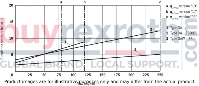
Size 25
Circulation pressure dependent on flow qV P and damping (P → T)
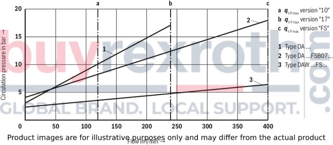
Size 32
Circulation pressure dependent on flow qV P and damping (P → T)
Notice!
The flow depends on the set switching pressure differential.
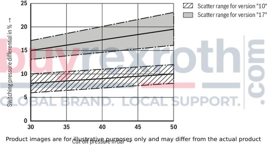
Pressure rating 50 bar
Switching pressure differential (P → A) dependent on the cut-off pressure pO (type DA …)
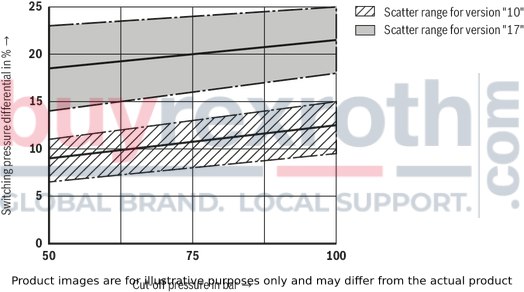
Pressure rating 100 bar
Switching pressure differential (P → A) dependent on the cut-off pressure pO (type DA …)
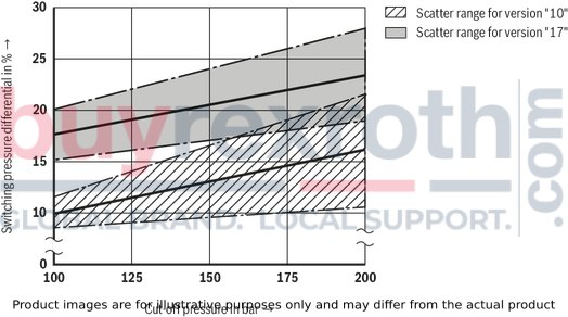
Pressure rating 200 bar
Switching pressure differential (P → A) dependent on the cut-off pressure pO (type DA …)
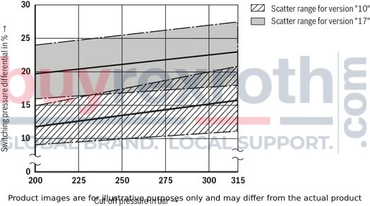
Pressure rating 315 bar
Switching pressure differential (P → A) dependent on the cut-off pressure pO (type DA …)
Switching pressure differential (P → A); pressure adjustment range pU dependent on the cut-off pressure pO (type DA …FS)

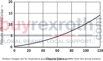
Size 10
Δp-qV characteristic curves via check valve (P → A)
Size 25
Δp-qV characteristic curves via check valve (P → A)
Size 32
Δp-qV characteristic curves via check valve (P → A)
Type DAW …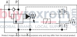
|
Type DAW …Y…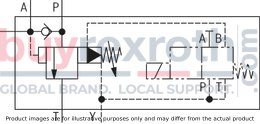
|
Normally closed
Normally open
|
Type DAW …FS…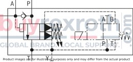
|
Type DAW …FS.Y…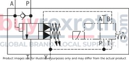
|
|
Type DAWC 30 …FS…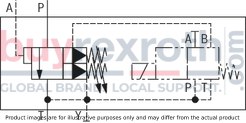
|
Type DAWC 30 …FS.Y…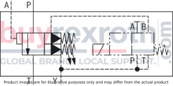
|
Hydraulic system with hydraulic accumulator

Hydraulic system with high- and low-pressure pump
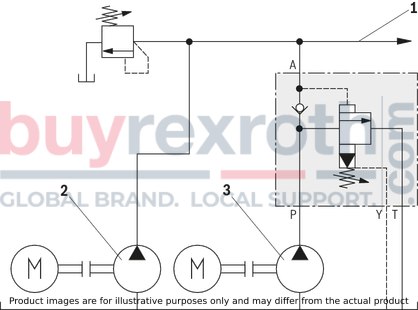
Application notes:
Reduce the tubing between pressure cut-off valve and hydraulic accumulator to a minimum! In case of high line resistance, use version "DA.../SO80" (separate control line from pilot control valve to hydraulic accumulator)! In case of high pump flow and low switching pressure differential (10 %), version "Y" should be preferred.Attention!
Accumulators may only be operated with suitable accumulator safety equipment! Version "FS" does not directly provide a pressure limiting function of the pump pressure (to the tank) but only indirectly via the check valve and the control line in the actuator channel. Observe the safety instructions on circuit design!|
1 |
to actuator |
|
2 |
High-pressure pump |
|
3 |
Low-pressure pump |
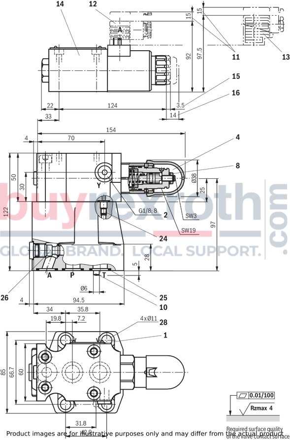
Type DAW…FS, NG10; subplate mounting
Dimensions in mm
|
1 |
Name plate |
|
2 |
Y port for pilot oil return, external |
|
4 |
Adjustment type "2" |
|
5 |
Adjustment type "3" |
|
8 |
Hexagon SW10 |
|
10 |
Locking pin |
|
11 |
Space required to remove the mating connector |
|
12
|
Mating connector without circuitry (separate order) |
|
13 |
Mating connector with circuitry (separate order) |
|
14 |
Directional spool valve NG6 |
|
15 |
Dimension for solenoid without manual override |
|
16 |
Dimension for solenoid with manual override “N” |
|
24 |
Omitted with internal pilot oil return |
|
25 |
Identical seal rings for ports A, P, T |
|
26 |
Integrated check valve |
|
28 |
Valve mounting bores (valve mounting screws, see dimensions) |
Valve mounting screws (separate order)
4 hexagon socket head cap screws
ISO 4762 - M10 x 50 - 10.9-flZn-240h-L
Friction coefficient µtotal = 0.09 to 0.14,
Tightening torque MA = 59 Nm ± 10 %,
material no. R913000471
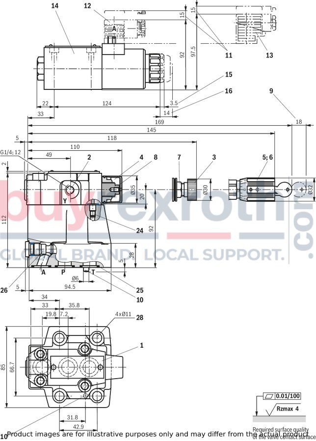
Type DAW…, NG10; subplate mounting
Dimensions in mm
|
1 |
Name plate |
|
2 |
Y port for pilot oil return, external |
|
3 |
Adjustment type "1" |
|
4 |
Adjustment type "2" |
|
5 |
Adjustment type "3" |
|
6 |
Adjustment type "7" |
|
7 |
Lock nut SW22 |
|
8 |
Hexagon SW10 |
|
9 |
Space required to remove the key |
|
10 |
Locking pin |
|
11 |
Space required to remove the mating connector |
|
12 |
Mating connector without circuitry (separate order) |
|
13 |
Mating connector with circuitry (separate order) |
|
14 |
Directional spool valve NG6 |
|
15 |
Dimension for solenoid without manual override |
|
16 |
Dimension for solenoid with manual override “N” |
|
24 |
Omitted with internal pilot oil return |
|
25 |
Identical seal rings for ports A, P, T |
|
26 |
Integrated check valve |
|
28 |
Valve mounting bores (valve mounting screws, see dimensions) |
Valve mounting screws (separate order)
4 hexagon socket head cap screws
ISO 4762 - M10 x 50 - 10.9-flZn-240h-L
Friction coefficient µtotal = 0.09 to 0.14,
Tightening torque MA = 59 Nm ± 10 %,
material no. R913000471
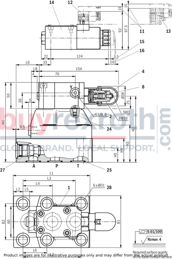
Type DAW…FS, NG25 and 32; subplate mounting
Dimensions in mm
|
1 |
Name plate |
|
2 |
Y port for pilot oil return, external |
|
4 |
Adjustment type "2" |
|
8 |
Hexagon SW10 |
|
11 |
Space required to remove the mating connector |
|
12 |
Mating connector without circuitry (separate order) |
|
13 |
Mating connector with circuitry (separate order) |
|
14 |
Directional spool valve NG6 |
|
15 |
Dimension for solenoid without manual override |
|
16 |
Dimension for solenoid with manual override “N” |
|
24
|
Omitted with internal pilot oil return |
|
25 |
Identical seal rings for ports A, P, T |
|
27 |
Check valve (sandwich plate) |
|
28 |
Valve mounting bores (valve mounting screws, see dimensions) |
Valve mounting screws (separate order)
NG25:4 hexagon socket head cap screws ISO 4762 - M16 x 100 - 10.9-flZn-240h-L
Friction coefficient µtotal = 0.09 to 0.14,
Tightening torque MA = 200 Nm ± 10 %,
material no. R913000558
2 hexagon socket head cap screws ISO 4762 - M16 x 60 - 10.9-flZn-240h-L
Friction coefficient µtotal = 0.09 to 0.14,
Tightening torque MA = 200 Nm ± 10 %,
material no. R913000031
NG32:
4 hexagon socket head cap screws M18 x 120 - DIN 912-10.9
Friction coefficient µtotal = 0.12 to 0.17,
Tightening torque MA = 300 Nm ± 10 %,
material no. R900003282
2 hexagon socket head cap screws M18 x 80 - DIN 912-10.9
Friction coefficient µtotal = 0.12 to 0.17,
Tightening torque MA = 300 Nm ± 10 %,
material no. R900003279
Type DAW…, NG25 and 32; subplate mounting
Dimensions in mm
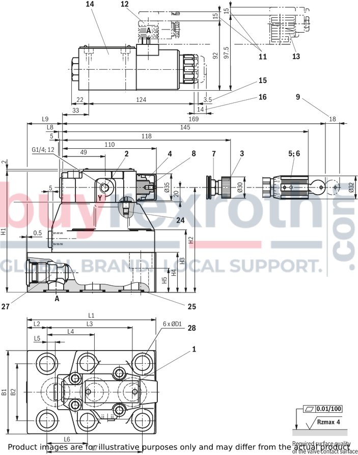
|
1 |
Name plate |
|
2 |
Y port for pilot oil return, external |
|
3 |
Adjustment type "1" |
|
4 |
Adjustment type "2" |
|
5 |
Adjustment type "3" |
|
6 |
Adjustment type "7" |
|
7 |
Lock nut SW22 |
|
8 |
Hexagon SW10 |
|
9 |
Space required to remove the key |
|
11 |
Space required to remove the mating connector |
|
12 |
Mating connector without circuitry (separate order) |
|
13 |
Mating connector with circuitry (separate order) |
|
14 |
Directional spool valve NG6 |
|
15 |
Dimension for solenoid without manual override |
|
16 |
Dimension for solenoid with manual override “N” |
|
24 |
Omitted with internal pilot oil return |
|
25 |
Identical seal rings for ports A, P, T |
|
27 |
Check valve (sandwich plate) |
|
28 |
Valve mounting bores (valve mounting screws, see dimensions) |
Type DAWC 30 …FS; cartridge valve
Dimensions in mm
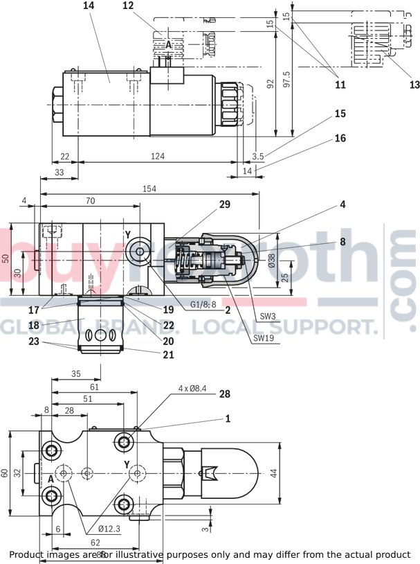
|
1 |
Name plate |
|
2 |
Y port for pilot oil return, external |
|
4 |
Adjustment type "2" |
|
8 |
Hexagon SW10 |
|
11 |
Space required to remove the mating connector |
|
12 |
Mating connector without circuitry (separate order) |
|
13 |
Mating connector with circuitry (separate order) |
|
14 |
Directional spool valve NG6 |
|
15 |
Dimension for solenoid without manual override |
|
16 |
Dimension for solenoid with manual override “N” |
|
17 |
Identical seal rings for ports A, Y |
|
18
|
Main piston |
|
19 |
O-ring |
|
20 |
O-ring |
|
21 |
O-ring |
|
22 |
Support ring |
|
23 |
Support ring |
|
28 |
Valve mounting bores (valve mounting screws, see dimensions) |
|
29 |
Tightening torque MA = 60 Nm |
Valve mounting screws (separate order)
4 hexagon socket head cap screws
ISO 4762 - M8 x 50 - 10.9-flZn-240h-L
at friction coefficient μtotal = 0.09 to 0.14,
Tightening torque MA = 30 Nm ± 10 %,
material no. R913000543
Type DAWC and DAWC 30; cartridge valve
Dimensions in mm
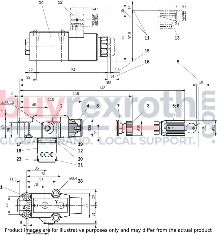
|
1 |
Name plate |
|
2 |
Y port for pilot oil return, external |
|
3 |
Adjustment type "1" |
|
4 |
Adjustment type "2" |
|
5 |
Adjustment type "3" |
|
6 |
Adjustment type "7" |
|
7 |
Lock nut SW22 |
|
8 |
Hexagon SW10 |
|
9 |
Space required to remove the key |
|
11 |
Space required to remove the mating connector |
|
12 |
Mating connector without circuitry (separate order) |
|
13 |
Mating connector with circuitry (separate order) |
|
14 |
Directional spool valve NG6 |
|
15 |
Dimension for solenoid without manual override |
|
16 |
Dimension for solenoid with manual override “N” |
|
17 |
Identical seal rings for ports A, Y |
|
18 |
Main piston |
|
19 |
O-ring |
|
20 |
O-ring |
|
21 |
O-ring |
|
22 |
Support ring |
|
23 |
Support ring |
|
28 |
Valve mounting bores (valve mounting screws, see dimensions) |
Valve mounting screws (separate order)
4 hexagon socket head cap screws
ISO 4762 - M8 x 40 - 10.9-flZn-240h-L
at friction coefficient μtotal = 0.09 to 0.14,
Tightening torque MA = 30 Nm ± 10 %,
material no. R913000205
Installation bore
Dimensions in mm
Dimensions in mm

|
1 |
Bore Ø32 mm can cut into Ø45 mm at any position. However, it must be observed that connection bore A and the mounting bores are not damaged! |
|
2 |
Support ring and seal rings are to be inserted into this bore before assembly of the main spool! |
|
3 |
Check valve (separate order). For positioning of the check valve and pilot oil bore, sufficient clearance to the main spool insert is to be ensured. |
|
NG |
L1 |
L2 |
L3 |
L4 |
L5 |
L6 |
L7 |
L8 |
L9 |
B1 |
B2 |
H1 |
H2 |
H3 |
H4 |
H5 |
ØD1 |
|
mm |
mm |
mm |
mm |
mm |
mm |
mm |
mm |
mm |
mm |
mm |
mm |
mm |
mm |
mm |
mm |
mm |
|
| 25 | 149 | 19 | 101.6 | 57.1 | 12.7 | 46 | 112.7 | 15.5 | 41.5 | 100 | 70 | 154 | 129 | 72 | 46 | 28 | 18 |
| 32 | 190 | 34 | 127 | 63.5 | 12.7 | 50.8 | 139.7 | 26 | 66.5 | 116 | 82.5 | 175 | 150 | 93 | 67 | 45 | 20 |
|
NG |
L1 |
L2 |
L3 |
L4 |
L5 |
L6 |
L7 |
L8 |
L9 |
B1 |
B2 |
H1 |
H2 |
H3 |
H4 |
H5 |
ØD1 |
|
mm |
mm |
mm |
mm |
mm |
mm |
mm |
mm |
mm |
mm |
mm |
mm |
mm |
mm |
mm |
mm |
mm |
|
| 25 | 149 | 19 | 101.6 | 57.1 | 12.7 | 46 | 112.7 | 12 | 42 | 100 | 70 | 144 | 124 | 72 | 46 | 28 | 18 |
| 32 | 190 | 34 | 127 | 63.5 | 12.7 | 50.8 | 139.7 | 22.5 | 63 | 115 | 82.5 | 165 | 145 | 93 | 67 | 45 | 20 |
Mating connectors for valves with connector “K4”, without circuitry, standard
3P Z4
Mating connectors for valves with connector “K4”, without circuitry, standard
3P Z4
For valves with connector “K4” according to EN 175301-803 and ISO 4400, 2-pole + PE, “large cubic connector” Mating connectors for valves with one or two solenoids (individual connection)Data sheet
Spare parts & repair
Mating connectors for valves with connector “K4”, with indicator light
3P Z5L
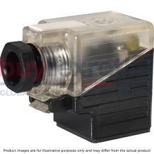
Mating connectors for valves with connector “K4”, with indicator light
3P Z5L
For valves with connector “K4” according to EN 175301-803 and ISO 4400, 2-pole + PE, “large cubic connector” Mating connectors for valves with one or two solenoids (individual connection)Data sheet
Spare parts & repair
Mating connectors for valves with connector “K4”, with indicator light and Zener diode suppression circuit
3P Z5L1

Mating connectors for valves with connector “K4”, with indicator light and Zener diode suppression circuit
3P Z5L1
For valves with connector “K4” according to EN 175301-803 and ISO 4400, 2-pole + PE, “large cubic connector” Mating connectors for valves with one or two solenoids (individual connection)Data sheet
Spare parts & repair
Mating connectors for valves with connector “K4”, with rectifier
3P RZ5

Mating connectors for valves with connector “K4”, with rectifier
3P RZ5
For valves with connector “K4” according to EN 175301-803 and ISO 4400, 2-pole + PE, “large cubic connector” Mating connectors for valves with one or two solenoids (individual connection)Data sheet
Spare parts & repair
Related Products
R978913395
$2,417.00 USD
R901375757
$3,329.00 USD
R900215709
$748.00 USD
R900958447
$3,348.00 USD
R901129841
$416.00 USD


