


INTERNAL GEAR PUMP PGP2-2X/006RE20VE4
Manufacturer: Bosch Rexroth
Material #: R900932129
Model : PGP2-2X/006RE20VE4
***Disclaimer: The following summary contains information gathered from various sources such as product descriptions, technical specifications and catalogs. While efforts have been made to provide accurate details, inaccuracies may occur. It is advised to verify all information by contacting Bosch Rexroth directly.***
The Bosch Rexroth PGP2-2X/006RE20VE4 (R900932129) is an internal gear pump designed for industrial applications requiring a reliable and efficient hydraulic power source. This pump is characterized by its fixed displacement, size 2, and capability to operate at a maximum pressure of 280 bar, making it suitable for heavy-duty operations. With a displacement of 6 cm³ per revolution, the PGP2-2X/006RE20VE4 ensures consistent performance in fluid transfer.
The aluminum housing of the pump contributes to its durability and suitability for up to one million load cycles at maximum permissible pressure. The design includes FKM seals which provide compatibility with HLP and HEES hydraulic fluids. The pump operates with a clockwise rotation and features a square flange connection conforming to DIN standards, allowing for straightforward installation.
With minimum speeds starting from 500 rpm and reaching up to a maximum speed of 3500 rpm, this pump can achieve a flow rate tailored to various operational needs. Its constant displacement type ensures steady flow regardless of system pressure changes. The low noise level and reduced pulsation are achieved through gap compensation technology, which also enhances the efficiency even at low viscosity levels.
The PGP2-2X/006RE20VE4 is engineered with hydrodynamically supported pinion shafts and hydrostatically supported ring gears that ensure smooth operation and longevity. It is compatible with other Bosch Rexroth pumps such as PGH and PGF internal gear pumps, vane pumps, and axial piston pumps, providing versatile integration options for complex hydraulic systems.
This pump's outstanding suction characteristics make it an excellent choice for applications demanding high operating pressures up to 280 bar for activities like trimming presses. Overall, the Bosch Rexroth PGP2-2X/006RE20VE4 offers reliability, high performance, and adaptability for demanding industrial environments requiring precise hydraulic control.
$1,697.43 USD
Availability: 2 In Stock
Ships from US Note: Sales tax, shipping, and applicable tariffs will be calculated at checkout.
Qty:
Delivered as early as July 13, 2026
$1,782.30 USD
Availability: Backordered
Ships from CA Note: Sales tax, shipping, and applicable tariffs will be calculated at checkout.
Qty:
Delivered as early as August 24, 2026
This product is eligible for factory repair.
Internal gear pump, size 6, pressure 350 bar for industrial applications, open circuit
Suitable for variable-speed drive. Low noise and pulsation level. High efficiency thanks to gap compensation. Aluminum housing, suitable for 1 million load cycles at maximum admissible pressure.
Unpacked Weight: 3.64 kg
Low operating noise Low flow pulsation High efficiency even at low viscosity due to sealing gap compensation Long service life due to slide bearings and sealing gap compensation Suitable for a wide viscosity and speed range Excellent suction characteristics Can be combined with PGH and PGF internal gear pumps, vane pumps and axial piston pumps Use:
For drives with high operating pressure up to 106 load cycles, for example trimming presses
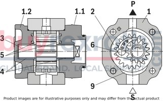
Design
PGP hydraulic pumps are leak-gap-compensated internal gear pumps with a fixed displacement.
They consist basically of: housing (1), bearing cover (1.1), cover (1.2), ring gear (2), pinion shaft (3), slide bearings (4), axial discs (5) and stop pin (6) as well as the segment assembly (7) which is composed of a segment (7.1), segment carrier (7.2) and the sealing rolls (7.3).
Suction and displacement process
The hydrodynamically supported pinion shaft (3) drives the internally toothed ring gear (2) in the direction of rotation shown.
During rotation, the volume is increased in the suction area over an angle of approx. 180°. A negative pressure is generated and fluid flows into the chambers.
The sickle-shaped segment assembly (7) separates the suction chamber from the pressure chamber. Within the pressure chamber, the teeth of the pinion shaft (3) mesh with the tooth spaces of the ring gear (2). The fluid is then displaced through the pressure channel (P).
Axial compensation
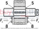
The axial compensation force FA acts in the area of the pressure chamber and is generated by the pressure zone (8) in the axial discs (5). The axial, longitudinal gaps between rotating and fixed parts are therefore extremely small and ensure optimum axial sealing of the pressure chamber.
Radial compensation
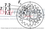
The radial compensation force FR acts on the segment (7.1) and segment carrier (7.2).
The area ratios and the position of the sealing rolls (7.3) between the segment and segment carrier are designed to provide virtually gap-free sealing between the ring gear (2), the segment assembly (7) and the pinion shaft (3).
Spring elements under the sealing rolls (7.3) ensure adequate contact pressure, even at very low pressures.
Hydrodynamic and hydrostatic bearing
The forces acting on the pinion shaft (3) are absorbed by hydrodynamically lubricated radial slide bearings (4) while those acting on the ring gear (2) are absorbed by the hydrostatic bearing (9).
Splines
Involute splining was selected for the gear. Their long length of contact results in a low flow and pressure pulsation; these low pulsation rates contribute greatly to the low-noise operation.
Used materials
Housing (1), bearing cover (1.1), cover (1.2) and axial discs (5): Steel-aluminum compound material
Ring gear (2), pinion shaft (3) and stop pin (6): Steel
Slide bearing (4): Copper-tin with steel back
Segment (7.1) and segment carrier (7.2): Brass alloy
Sealing rolls (7.3): Plastic
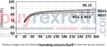
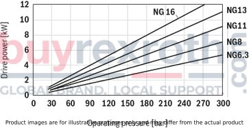
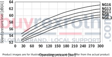
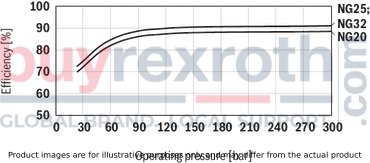
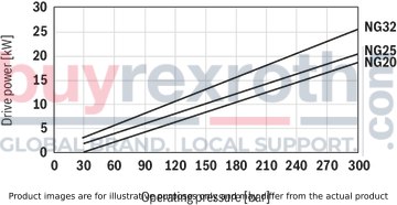
Frame size 2
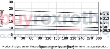
Flow
Efficiency
Drive power
Sound pressure level
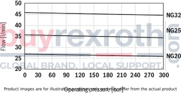
Frame size 3
Flow
Efficiency
Drive power
Sound pressure level
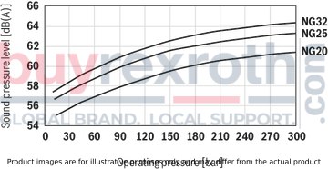
Note
Characteristics measured at n = 1450 rpm; ν = 46 mm2/s; θ = 40 °C
Sound pressure level measured in acoustic room according to DIN 45635, Sheet 26; Distance: microphone ‒ pump = 1 m
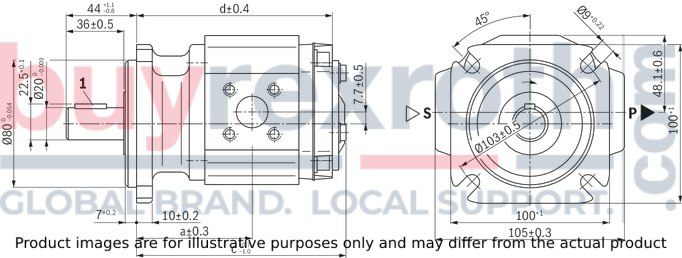
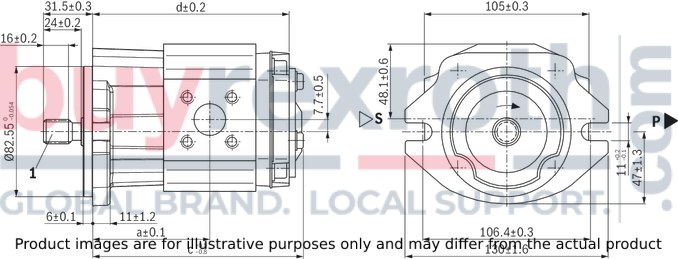
Symbol

Frame size 2
Parallel keyed shaft, DIN 6885, with through drive
Dimensions in mm
|
1 |
Shaft key B6 × 6 × 25 |
|
Type |
a |
c |
d |
S 1) 2) |
P 2) 3) |
|
mm |
mm |
mm |
mm |
mm |
|
| PGP2-2X/006RE20VE4 | 63 | 115.2 | 104.1 | Ø20, TK Ø40 | Ø6, TK Ø35 |
| PGP2-2X/008RE20VE4 | 64.8 | 118.7 | 107.6 | Ø8, TK Ø35 | |
| PGP2-2X/011RE20VE4 | 67.5 | 124.2 | 113.1 | Ø12, TK Ø35 | |
| PGP2-2X/013RE20VE4 | 70 | 129.2 | 118.1 | ||
| PGP2-2X/016RE20VE4 | 72.5 | 134.2 | 123.1 |
| 1) | Fastening thread M6; 10 deep |
| 2) | See line connections |
| 3) | Fastening thread M6; 12 deep |
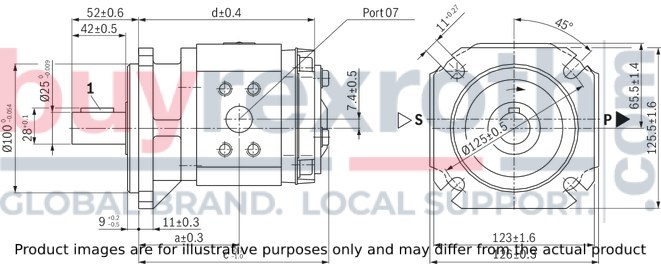
Splined shaft, with through-drive
Dimensions in mm
|
1 |
SAE J744 16-4(A) 9T 16/32 DP |
|
Type |
a |
c |
d |
S 1) 2) |
P 2) 3) |
|
mm |
mm |
mm |
mm |
mm |
|
| PGP2-2X/006RJ20VU2 | 65 | 117.2 | 106.1 | Ø20, TK Ø40 | Ø6, TK Ø35 |
| PGP2-2X/008RJ20VU2 | 66.8 | 120.7 | 109.6 | Ø8, TK Ø35 | |
| PGP2-2X/011RJ20VU2 | 69.5 | 126.2 | 115.1 | Ø12, TK Ø35 | |
| PGP2-2X/013RJ20VU2 | 72 | 131.2 | 120.1 | ||
| PGP2-2X/016RJ20VU2 | 74.5 | 136.2 | 125.1 |
| 1) | Fastening thread M6; 10 deep |
| 2) | See line connections |
| 3) | Fastening thread M6; 12 deep |
TK = Pitch circle
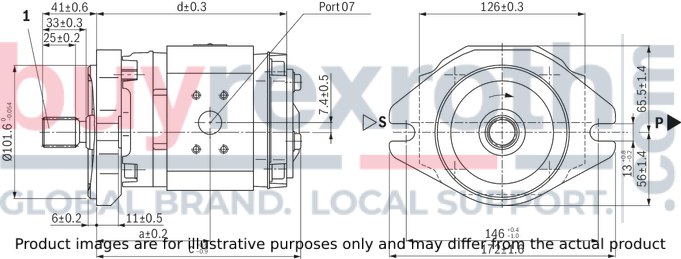
Frame size 3
Parallel keyed shaft, DIN 6885, with through drive
Dimensions in mm
|
1 |
Shaft key B8 × 7 × 30 |
|
Type |
a |
c |
d |
S 2) |
P 2) |
|
mm |
mm |
mm |
mm |
mm |
|
| PGP3-3X/020RE20VE4 | 71 | 137.1 | 126 | Ø26, TK Ø55 1) | Ø12, TK Ø35 4) |
| PGP3-3X/025RE20VE4 | 74 | 143.1 | 132 | ||
| PGP3-3X/032RE07VE4 | 78.5 | 152.1 | 141 | SAE 1 1/4 in S 3) | SAE 3/4 in S 3) |
| 1) | Fastening thread M8; 12 deep |
| 2) | See line connections |
| 3) | Standard pressure series |
| 4) | Fastening thread M6; 12 deep |
Splined shaft, with through-drive
Dimensions in mm
|
1 |
SAE J744 22-4(B) 13T 16/32 DP |
|
Type |
a |
c |
d |
S 2) |
P 2) |
|
mm |
mm |
mm |
mm |
mm |
|
| PGP3-3X/020RJ20VU2 | 79.5 | 145.6 | 134.5 | Ø26, TK Ø55 1) | Ø12, TK Ø35 4) |
| PGP3-3X/025RJ20VU2 | 82.5 | 151.6 | 140.5 | ||
| PGP3-3X/032RJ07VU2 | 92 | 160.6 | 149.5 | SAE 1 1/4 in S 3) | SAE 3/4 in S 3) |
| 1) | Fastening thread M8; 12 deep |
| 2) | See line connections |
| 3) | Standard pressure series |
| 4) | Fastening thread M6; 12 deep |
TK = Pitch circle
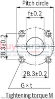
Line connections
Port type 20 square flange port
Suction port S
Dimensions in mm
Pressure port P
Dimensions in mm
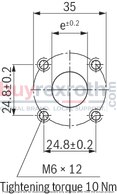
|
Size |
Pitch circle |
G |
t |
e |
f |
M |
|
mm |
mm |
mm |
mm |
Nm |
||
| 6.3 | 40 | M6 | 10 | 6 | 20 | 10 |
| 8 | 8 | |||||
| 11 | 12 | |||||
| 13 | ||||||
| 16 | ||||||
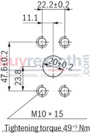
| 20 | 55 | M8 | 12 | 26 | 25 | |
| 25 | ||||||
| 32 | - | - | - | - | - | - |
Port type 07, SAE flange port, for Size 32
Suction port S SAE 1 1/4 in
Dimensions in mm
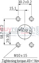
Pressure port P SAE 3/4 in
Dimensions in mm
Intended use
Internal gear pumps are intended for the assembly of hydraulic drive systems in machine and system construction.
Technical data
The system or machine manufacturer must ensure compliance with the permissible technical data and operating conditions. The pump itself does not contain a device to prevent operation outside the permissible data. It is possible to operate the pump outside of the permissible technical data to a certain extent; the express written consent from Bosch Rexroth is, however, required.
All specified technical performance features are median values and apply with the specified general conditions. In case of modifications to the general conditions (e.g., viscosity), the technical data may change as well. Scatter corresponding to the relevant state of technology is possible.
Hydraulic project planning
Air bleeding option for commissioning
For Rexroth PGP2-2X internal gear pumps, a manual or switchable air bleeding option for the initial commissioning or any recommissioning after maintenance and repair work is to be provided. The air bleeding point is to be set in the pressure line before the first valve or check valve. Air bleeding may be performed with a maximum counter pressure of 0,2 bar.
Examples of air bleeding circuits
Switchable bleeding
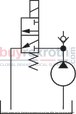
Manually operated bleeding

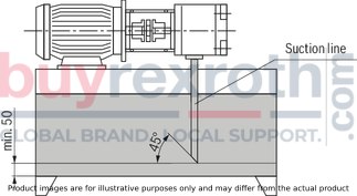
Suction line
The line cross sections are to be dimensioned for the specified flows such that an ideal suction speed of 0.6 to 1.2 m/s is achieved on average. The suction speed should not exceed a maximum value of 2 m/s.
The suction cross sections at the pump itself are designed for the maximum flow and therefore serve only as reference. In case of continuous operation at rotational speeds lower than the permissible maximum speed, the suction tube diameter is also to be dimensioned smaller than the suction port of the pump depending on the actual suction speed.
Overall, the suction line is to be designed so that the permissible inlet operating pressure is maintained. Bends and a combination of suction pipes from several pumps are to be avoided. If the use of a suction filter is unavoidable, it must be ensured on the system side that the lowest permissible inlet operating pressure is not exceeded even if the filter is contaminated.
Ensure the air tightness of the transitions and the pressure resistance of the suction hose with respect to the external air pressure.
The immersion depth of the suction pipe should be selected as large as possible (at least 100 mm at the lowest fluid level). Depending on the internal reservoir pressure, the viscosity of the operating medium and the flow conditions within the reservoir, no vortex may form even at maximum flow. There is otherwise a risk of air being drawn in. Return fluid and case drain fluid must not be immediately be drawn in again.
Dimensions in mm
Pressure line
Sufficient burst resistance of the pipes, hoses and connecting elements must be ensured for pressure lines. The cross sections should be based on the maximum flow in order to avoid additional excessive loading of the pump due to back-pressure. Here, you must also take into account the pipe losses over the entire pressure line length and other line resistances (e.g., bends, pressure filters).
Pressure safeguarding
The PGP internal gear pump does not include any devices for adherence to the maximum operating pressure. The setting and safeguarding of the permissible operating pressure must be ensured on the system side.
The pressure-relief valves necessary for this purpose are to be designed with consideration given to the maximum flow and the rate of pressure increase that will occur such that the permissible intermittent operating pressure is not exceeded.
Pressure holding function
In the variable-speed drive, the pump can also be temporarily operated in the pressure holding function below the specified minimum rotational speed. The holding time and the rotational speed necessary for this purpose are a function of the operating viscosity and the pressure level. For the design, please contact Bosch Rexroth‘s technical sales department.
In the deactivated state (rotational speed = 0), a leakage flow flows through the pump back into the reservoir, depending on the load pressure. If this is to be prevented, a check valve is to be used.
When using a check valve, please observe the note on the air bleeding option for commissioning.
Mechanical project planning
Mounting
On the machine side, the screws are to be accessible in such a way that the required tightening torque can be applied. The screw tightening torque is oriented towards the operating conditions and elements involved in the screw connection and is to be specified by the manufacturer during project planning of the power unit, the machine, or the system.
Reservoir
When designing the reservoir or selecting a suitable standard reservoir, the following requirements are to be observed:
Select the largest possible reservoir volume, depending on the continuous or average flow, which is needed in order to allow separation of air bubbles by means of sufficient dwell time of the medium in the reservoir. The air separation ability of the used hydraulic fluid is also of importance here. Provide settling zones for the hydraulic fluid in the reservoir in order to allow for air separation. Provide guiding plates in order to allow contamination at the reservoir bottom to be deposited outside the pump suction area. Generously dimension the reservoir surfaces depending on the heat output to be dissipated via the reservoir walls.
Required power unit functions
At a minimum, the hydraulic power units should be equipped with the following features:
Reservoirs that are designed so that the internal pressure corresponds to the ambient pressure should be equipped with ventilation filters for pressure compensation purposes. The hydraulic fluid should only be filled using filling nozzles that eliminate the possibility of filling with unfiltered fluid. The ingress of contamination or moisture must be avoided. If used in highly contaminated environments, the reservoir must, for this purpose, be precharged by means of air pressure. If cleaning of the reservoir exterior is planned or anticipated during the period of use, reservoir bushings for pipes, lines, or hoses are to be selected so that a secure seal is ensured against external pressurization with a water jet.
Place of installation and ambient conditions
With places of installation at a geodetic height of more than 1000 m, the pump is to be arranged in or below the reservoir or the reservoir is to be precharged by means of compressed air in order to ensure the permissible minimum inlet pressure. A short suction line with large cross section is to be selected; bends should not be used.
When installing the pump more than 10 m below the reservoir, the reduction of the inlet pressure to the maximum permissible value must be ensured by means of additional measures.
If operating the pump in salt-containing or corrosive environments or if there is a possibility of pressurization with strongly abrasive substances, it must be ensured on the system side that the shaft seal ring and the sealing area of the shaft do not make direct contact with the environment.
Drive
Electric motor + pump support + coupling + pump
No radial or axial forces permissible on the pump drive shaft! Motor and pump must be exactly aligned! Always use a coupling that is suitable for compensating for shaft offsets!Installation positions
B3
B5

V1
Pump combinations
With pump combinations, make sure that the operating data approved for the pump type concerned can be complied with in every step. Combined pumps must all have the same direction of rotation. The pump with the highest torque, variable pumps or pumps with intermittent pressure loading should be specified as the first step in the pump combination. The engineer must verify the maximum through-drive torque for every application. This also applies for existing (coded) pump combinations. The sum of all input torques in a pump combination may not exceed the permissible input torque of the first pump.Maximum input torques
|
Shaft version E |
140 Nm |
|
Shaft version J |
90 Nm |
Formula for input torque

|
|
|
Key |
|
|
T |
Input torque [Nm] |
|
Δp |
Operating pressure [bar] |
|
V |
Displacement [cm³] |
|
η |
Hydraulic-mechanical efficiency |
Maximum output torques
|
Shaft version E |
70 Nm |
|
Shaft version J |
70 Nm |
Selection
The front pump must have shaft version E or J. The middle pump must have shaft version L. The rear pump must have shaft version N. If a pump of the next smaller frame size is to be mounted, the designation of the first pump must end with “K” (e.g., PGP3 + PGF2 ⇒ front pump: PGP3-3X/032RE07VE4K)Dimensions
The dimensions of the ports are the same as for single pumps (see dimensions). The total length of the pump combination is calculated by adding up dimensions “d” of the single pumps (see dimensions). With the combination of PGP2 and PGF1, the installation length of the PGP2 (dimension d) increases by 4.5 mm.Related Products
R900932129
$1,697.43 USD
R900932114
$1,786.23 USD

R900984022
$1,585.92 USD
R900932177
$1,897.74 USD
R900984020
$1,786.23 USD


