


PREFILL VALVE ZSF 50 F1-1-1X/M/12D00
Manufacturer: Bosch Rexroth
Material #: R900539731
Model : ZSF 50 F1-1-1X/M/12D00
***Disclaimer: The following summary contains information gathered from various sources such as product descriptions, technical specifications and catalogs. While efforts have been made to provide accurate details, inaccuracies may occur. It is advised to verify all information by contacting Bosch Rexroth directly.***
The Bosch Rexroth ZSF 50 F1-1-1X/M/12D00 (R900539731) is a high-performance, mechanically actuated industrial hydraulic seat valve designed for robust and efficient operation. This model features a pilot-operated configuration with a high-pressure connection and an additional high-pressure port, complemented by a pipe thread UNF/UN according to ANSI/ASME B. It's crafted for installation bore accommodation for throttle check valves and is characterized by its spool symbol A + B, ensuring reliable control of hydraulic flow.
With the capability to handle a maximum pressure as indicated in its product group ID, this valve is engineered to meet demanding applications. The ZSF 50 F1-1-1X/M/12D00 comes equipped with multiple ports and supports mechanical actuation. Its size and type of connection are designed for interim assembly, offering flexibility in system integration.
The nominal flow rate and individual connection diagram are specified per the model, ensuring compatibility with various hydraulic systems. This valve also boasts numerous switching positions and maintains a weight that contributes to its stability and ease of installation.
Seals made from NBR ensure compatibility with a range of hydraulic fluids including HL, HLP, HLPD, HVLP, HVLPD, and HFC types. For optimal performance, it's important to note that sizes require a separately ordered nozzle in channel P of the upstream directional valve; failure to comply can result in increased dynamic loads which may affect operational longevity.
The Bosch Rexroth ZSF 50 F1-1-1X/M/12D00 also includes an integrated throttle check valve for sizes NG6, NG10, NG16, and NG25. It operates within a designated component series X or X2 at maximum pressures up to bar levels and can handle maximum flow rates expressed in liters per minute (l/min), ensuring reliable performance across various industrial applications.
This product is not available. CLICK HERE to create a support ticket for us to locate your part or a suitable replacement
This product is eligible for factory repair.
Size 50, A → B, mechanically actuated
Industrial hydraulic valve in a high performance range.
Unpacked Weight: 5.54 kg
Notice:
With size 32, 40, 100, 125, 160 a nozzle (separate order) must imperatively be provided in channel P of the upstream directional valve. The nozzle diameter is to be designed according to the prefill valve size (see "Schematics").
In case of non-compliance, increased dynamic loads may occur having detrimental effects on the operating time.
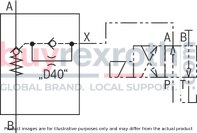
Type ZSF… (NG32, 40, 100, 125, 160)
Type ZSF… (NG200)
general
|
Size |
32 | 40 | 50 | 63 | 80 | 100 | 125 | 160 | 200 | |
|
Weight |
kg |
3.5 | 4.2 | 5.5 | 7 | 10 | 15 | 26 | 47 | 150 |
|
Installation position 1) |
any | |||||||||
|
Ambient temperature range |
°C |
-30 … +80 | ||||||||
| 1) | Working direction of the control spool |
hydraulic
|
Size |
32 | 40 | 50 | 63 | 80 | 100 | 125 | 160 | 200 | ||
|
Maximum operating pressure |
Port P |
bar |
350 | ||||||||
|
Anschluss A |
bar |
16 | |||||||||
|
Port B |
bar |
350 | |||||||||
|
Anschluss X |
bar |
150 | |||||||||
|
Cracking pressure 1) |
bar |
≈ 0.12 | |||||||||
|
Flow (Δp = 0.3 bar) |
Depending on the case of application, see below | ||||||||||
|
Druckflüssigkeit |
see table | ||||||||||
|
Hydraulic fluid temperature range |
°C |
-30 … +70 | |||||||||
|
Viscosity range |
mm²/s |
10 … 800 | |||||||||
|
Maximum admissible degree of contamination of the hydraulic fluid 2) |
Class 20/18/15 according to ISO 4406 (c) | ||||||||||
| 1) | Pressure differential at the main poppet for overcoming the spring force |
| 2) | The cleanliness classes specified for the components must be adhered to in hydraulic systems. Effective filtration prevents faults and simultaneously increases the life cycle of the components. For the selection of the filters, see www.boschrexroth.com/filter. |
|
Hydraulic fluid |
Classification |
Suitable sealing materials |
Standards |
Data sheet |
|
|
Mineral oils |
HL, HLP, HLPD, HVLP, HVLPD |
NBR, FKM |
DIN 51524 |
90220 |
|
|
Bio-degradable |
Insoluble in water |
HETG |
FKM |
ISO 15380 |
90221 |
|
HEES |
FKM |
||||
|
Soluble in water |
HEPG |
FKM |
ISO 15380 |
||
|
Flame-resistant |
Water-free |
HFDU (glycol base) |
FKM |
ISO 12922 |
90222 |
|
HFDU (ester base) |
FKM |
||||
|
HFDR |
FKM |
||||
|
Containing water |
HFC (Fuchs Hydrotherm 46M, Petrofer Ultra Safe 620) |
NBR |
ISO 12922 |
90223 |
|
|
Important information on hydraulic fluids: For further information and data on the use of other hydraulic fluids, please refer to the data sheets above or contact us. There may be limitations regarding the technical valve data (temperature, pressure range, life cycle, maintenance intervals, etc.). The ignition temperature of the hydraulic fluid used must be 50 K higher than the maximum surface temperature. Flame-resistant – containing water: Maximum pressure differential 210 bar, otherwise, increased cavitation erosion Life cycle as compared to operation with mineral oil HL, HLP 30 … 100% Maximum hydraulic fluid temperature 60 °C Bio-degradable and flame-resistant: If this hydraulic fluid is used, small amounts of dissolved zinc may get into the hydraulic system. |
|||||
Flow qV in l/min (A to B) for different cases of application (Δp = 0,3 bar)
|
Size |
32 | 40 | 50 | 63 | 80 | 100 | 125 | 160 | 200 | |
|
Case of application 1 |
l/min |
200 | 300 | 500 | 800 | 1200 | 1900 | 3000 | 4200 | 7000 |
|
Case of application 2 |
l/min |
170 | 250 | 400 | 650 | 1000 | 1600 | 2600 | 3900 | 6510 |
|
Case of application 3 |
l/min |
140 | 220 | 360 | 560 | 900 | 1400 | 2200 | 3400 | 5670 |
|
Case of application 4 |
l/min |
100 | 150 | 240 | 380 | 620 | 950 | 1500 | 2300 | 3850 |
|
Case of application 5 |
l/min |
70 | 110 | 170 | 280 | 450 | 700 | 1100 | 1690 | 2800 |
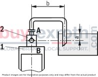
Case of application 1
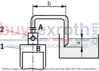
Case of application 2
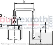
Case of application 3
Size of the filling tank at least 1.5 x cylinder content
Case of application 4
Case of application 5
Information on case of application 2 to 5
For limit areas, please contact us. It is often enough, to select a pipeline which is one size larger.

Note:
Wrong dimensioning of prefill valve and suction line may cause cavitation and consequential damage.
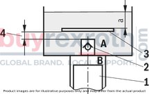
|
1 |
Cylinders |
|
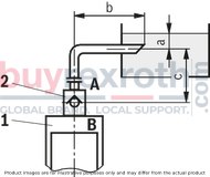
2 |
Prefill valve |
|
3 |
This sheet is not included in the scope of delivery. With smaller tank dimensions and minimum hydraulic fluid level (a), it prevents the formation of tunnels. |
|
4 |
Observe the supply cross-section |
|
a |
at least 300 mm with extended cylinder |
|
b |
up to 1000 mm with the specified maximum flows |
|
c |
h ≤ 500 mm |
|
h |
300 mm ≤ h < 500 mm |
For applications outside these parameters, please consult us!
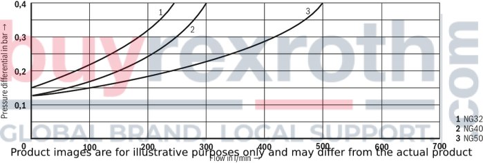
(measured with HLP46, ϑOil = 40 ±5 °C)
Size 32, 40, and 50
Pressure differential Δp between ports A and B dependent on the flow qV (A to B).
Size 63, 80 and 100
Pressure differential Δp between ports A and B dependent on the flow qV (A to B).

Size 125, 160, and 200
Pressure differential Δp between ports A and B dependent on the flow qV (A to B).

Without throttle check valve, NG32, 40, 100, 125, 160
Separate, external nozzle fitting required (see "Dimensions - Nozzle fitting")

With throttle check valve, NG50, 63, 80
Throttle check valve installed at the factory; no nozzle required

NG200
Throttle check valve installed at the factory; no nozzle required
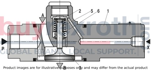
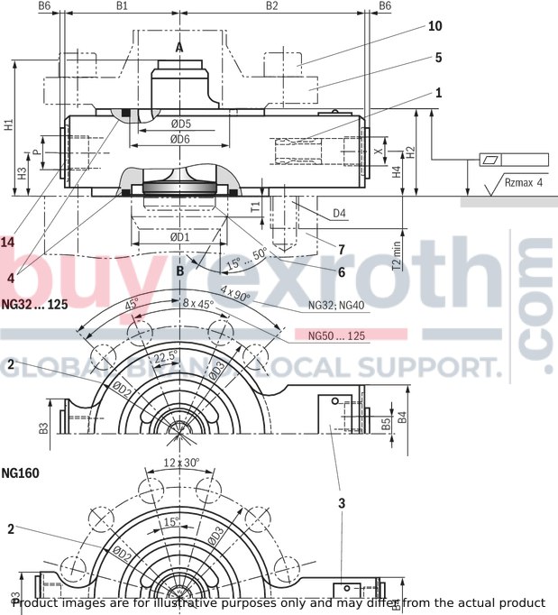
NG32 … 160
Dimensions in mm

|
|
Required surface quality of the valve contact surface |
|
1 |
Throttle check valve (only NG50, 63, 80, 200) |
|
2 |
Centering diameter |
|
3 |
Name plate |
|
4 |
Seal rings |
|
5 |
Counterflange (separate order, see "dimensional proposal for counterflange") |
|
6 |
Stroke of main poppet (see "Poppet geometry and determination of the minimum pilot pressure") |
|
7 |
Note: Valve contact face (e.g. pressing cylinders, bearing structures, etc.) must be sufficiently rigid. The prefill valve must not be loaded by bending. |
|
9 |
Space required to remove the mating connector |
|
10 |
Valve mounting screws (separate order) |
|
11 |
Threads for transport device (ring bolts), evenly distributed to circumference |
|
12 |
Measuring point, tightening torque MA = 30 Nm ±10% |
|
13 |
Damping nozzle M8 x 1 |
|
14 |
Additional pressure port; if not used, seal in a hydraulically tight way by means of suitable plug screws. |
|
NG |
B1 |
B2 |
B3 |
B4 |
B5 |
B6 |
ØD1 |
ØD2 |
ØD3 |
D4 |
ØD5 |
ØD6 |
H1 |
H2 |
H3 |
H4 |
P |
T1 |
T2 |
X |
|
|
mm |
mm |
mm |
mm |
mm |
max. mm |
mm |
mm |
mm |
mm |
mm |
mm |
mm |
mm |
mm |
mm |
mm |
min. mm |
||||
| 32 | 65 | 110 | 40 | 55 | 7.5 | 1.5 | 46 | 93 | 110 | ± 0.2 | M16 | 42 | 49.5 | 77 | 50 | 26.5 | 26.5 | G1/2 | 8 | 30 | G1/4 |
| 40 | 70 | 115 | 40 | 55 | 7.5 | 1.5 | 58 | 108 | 125 | ± 0.2 | M16 | 52 | 61.5 | 80 | 50 | 26.5 | 26.5 | G1/2 | 10 | 35 | G1/4 |
| 50 | 110 | 140 | 40 | 55 | 7.5 | 1.5 | 71 | 128 | 145 | ± 0.2 | M16 | 70 | 75.7 | 97 | 50 | 26.5 | 26.5 | G1/2 | 12 | 30 | G1/4 |
| 63 | 115 | 145 | 45 | 55 | 7.5 | 1.5 | 90 | 143 | 160 | ± 0.2 | M16 | 83 | 97.7 | 110 | 55 | 27.5 | 27.5 | G3/4 | 14 | 35 | G1/4 |
| 80 | 125 | 160 | 45 | 55 | 7.5 | 1.5 | 107 | 169 | 190 | ± 0.2 | M20 | 100 | 112 | 123 | 60 | 30 | 30 | G3/4 | 16 | 30 | G1/4 |
| 100 | 140 | 190 | 55 | 55 | 7.5 | 1.5 | 132 | 212 | 240 | ± 0.2 | M27 | 124 | 138.5 | 145 | 65 | 32.5 | 40 | G1 | 25 | 55 | G3/8 |
| 125 | 180 | 210 | 65 | 60 | 0 | 1.5 | 170 | 248 | 280 | ± 0.2 | M30 | 148 | 176 | 215 | 75 | 37.5 | 50 | G1 | 33 | 50 | G3/8 |
| 160 | 220 | 255 | 70 | 60 | 0 | 1.5 | 220 | 310 | 345 | ± 0.2 | M33 | 200 | 233 | 279 | 95 | 48.5 | 68 | G1 1/4 | 55 | 50 | G1/2 |
| 200 | - | - | - | - | - | - | - | - | - | - | - | - | - | - | - | - | - | - | - | - | - |
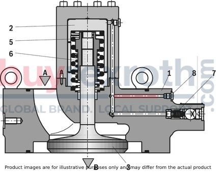
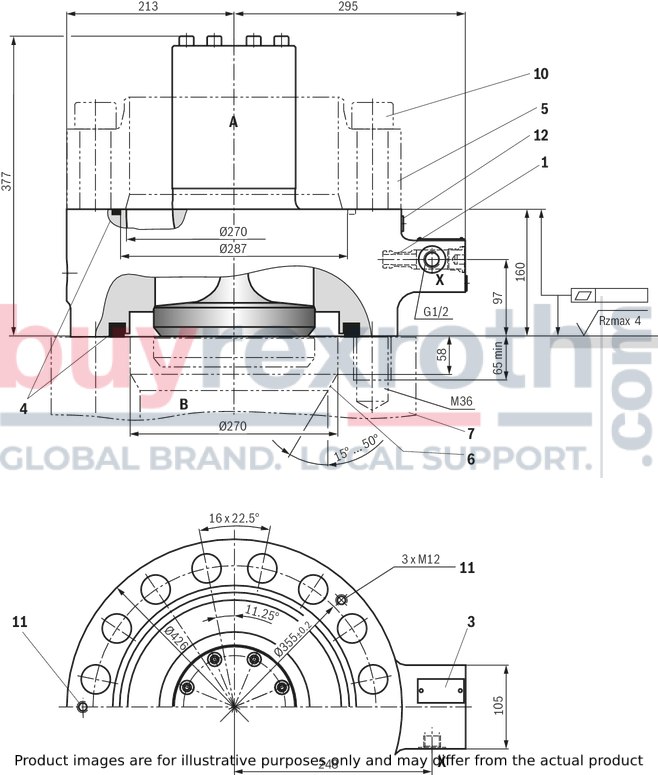
NG200
Dimensions in mm
|
|
|
Required surface quality of the valve contact surface |
|
1 |
Throttle check valve (only NG50, 63, 80, 200) |
|
3 |
Name plate |
|
4 |
Seal rings |
|
5 |
Counterflange (separate order, see "dimensional proposal for counterflange") |
|
6 |
Stroke of main poppet (see "Poppet geometry and determination of the minimum pilot pressure") |
|
7 |
Note: Valve contact face (e.g. pressing cylinders, bearing structures, etc.) must be sufficiently rigid. The prefill valve must not be loaded by bending. |
|
10 |
Valve mounting screws (separate order) |
|
11 |
Threads for transport device (ring bolts), evenly distributed to circumference |
|
12 |
Measuring point, tightening torque MA = 30 Nm ±10% |
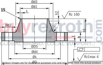
Dimensional proposal for counterflange (pos. 5)
Dimensions in mm

|
|
Required surface quality of the valve contact surface |
|
Size |
32 | 40 | 50 | 63 | 80 | 100 | 125 | 160 | 200 | |
|
Maximum operating pressure pmax 1) |
350 bar | |||||||||
|
Recommended flange material |
C22 | S355J2G3 | ||||||||
| 1) | When using other counterflanges than the ones specified here, it may be necessary to reduce the operating pressure. |
Form of the welding gap (15):
Standard version s ≤ 16 gap form 22 DIN 2559 s > 16 gap form 3 DIN 2559 special version see DIN 2559|
NG |
Flange |
Neck |
Raised face |
||||||||||
|
Ød1 |
Ød2 |
ØD |
ØD5+2 |
b |
Øk |
h1 |
Ød3 |
s |
r |
h2 |
Ød4 |
f |
|
|
mm 1) |
mm |
mm |
mm |
mm |
mm |
mm |
mm |
mm 1) |
mm |
mm |
mm |
mm |
|
| 32 | 48.3 | 18 | 150 | 42 | 22 | 110 | 49 | 64 | 3.2 | 6 | 7 | 88 | 3 |
| 40 | 60.3 | 18 | 165 | 52 | 29 | 125 | 57 | 75 | 3.6 | 6 | 8 | 102 | 3 |
| 50 | 76.1 | 18 | 185 | 70 | 34 | 145 | 64 | 90 | 3.6 | 6 | 10 | 122 | 3 |
| 63 | 88.9 | 18 | 200 | 83 | 43 | 160 | 77 | 105 | 3.6 | 8 | 12 | 138 | 3 |
| 80 | 114.3 | 22 | 235 | 100 | 51 | 190 | 95 | 134 | 3.6 | 8 | 12 | 162 | 3 |
| 100 | 139.7 | 30 | 295 | 124 | 62 | 240 | 116 | 168 | 4 | 8 | 12 | 188 | 3 |
| 125 | 168.3 | 33 | 345 | 148 | 79 | 280 | 138 | 202 | 4.5 | 10 | 12 | 218 | 3 |
| 160 | 219.1 | 36 | 415 | 200 | 118 | 345 | 186 | 256 | 5.9 | 10 | 16 | 285 | 3 |
| 200 | 273 | 39 | 420 | 270 | 100 | 355 | 140 | 292 | 6.5 | 6 | 16 | - | - |
| 1) | For seamless steel pipes, wall thickness 16 according to DIN EN 10220 |
Valve mounting screws, counterflange (separate order)
|
Hexagon socket head cap screw ISO 4762 - 10.9-flZn (or DIN 912 - 10.9-flZn) |
Counterflange |
||||
|
Size |
Dimensions |
Quantity |
Tightening torque MA in Nm (±5 %) 1) |
Material number |
Material number |
|
32 |
M16 x 100 |
4 |
240 |
R913015640 |
R900842693 |
|
40 |
M16 x 110 |
4 |
240 |
R913015642 |
R900825610 |
|
50 |
M16 x 110 |
8 |
240 |
R913015642 |
R900826441 |
|
63 |
M16 x 130 |
8 |
240 |
R913014713 |
R900849622 |
|
80 |
M20 x 140 |
8 |
460 |
R913015675 |
R900862915 |
|
100 |
M27 x 180 |
8 |
1150 |
R913059494 |
R900834583 |
|
125 |
M30 x 200 |
8 |
1600 |
R913015753 |
R900861508 |
|
160 |
M33 x 260 |
12 |
2200 |
R913001904 |
R900846478 |
|
200 |
M36 x 320 |
16 |
2600 |
R913050473 |
R901205467 |
| 1) | Friction coefficient μtotal = 0.09 … 0.14; please adjust in case of changed surfaces; use a manual torque wrench. |
Notice:
The information on the hexagon socket head cap screws (type, length, tightening torque) refers exclusively to the use with the counterflanges listed above.
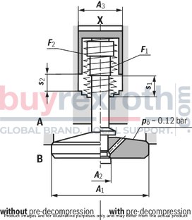
Poppet geometry and determination of the minimum pilot pressure
Dimensions in mm
|
A1 |
Effective area of the main poppet |
|
A2 |
Effective area of the pilot poppet |
|
A3 |
Effective area of the control spool |
|
s1 |
Stroke of the main poppet |
|
s2 |
Stroke of the control spool |
|
F1 |
Spring force of the valve spring |
|
F2 |
Spring force of the compression spring of the control spool |
|
Vst |
Pilot volume for opening the valve |
|
pÖ |
Cracking pressure (pressure differential at the main poppet for overcoming the spring force F1) |
|
pSt |
Pilot pressure at port X |
|
pB |
System pressure at port B |
|
NG |
A1 |
A2 1) |
A3 |
s1 |
s2 |
F1 |
F2 |
VstX |
Unchecking ratio |
|
|
cm² |
cm² |
cm² |
mm |
mm |
N |
N |
cm³ |
Without pre-decompression |
With pre-decompression 2) |
|
| 32 | 8.04 | 0.5 | 2.01 | 8.5 | 6.5 | 9 … 22 | 58 … 109 | 1.3 | 4 | 0.3 |
| 40 | 13.52 | 0.79 | 3.14 | 10 | 7 | 14 … 29 | 93 … 162 | 2.2 | 4.3 | 0.3 |
| 50 | 21.24 | 1.13 | 4.71 | 12.5 | 9 | 23 … 49 | 149 … 261 | 4.2 | 4.5 | 0.3 |
| 63 | 32.67 | 1.77 | 7.07 | 14.5 | 11 | 35 … 63 | 206 … 348 | 7.8 | 4.6 | 0.3 |
| 80 | 49.02 | 2.54 | 10.18 | 17 | 13 | 57 … 127 | 310 … 579 | 13.2 | 4.8 | 0.3 |
| 100 | 73.13 | 3.8 | 15.9 | 22 | 15 | 81 … 193 | 476 … 952 | 25.5 | 4.6 | 0.2 |
| 125 | 120.76 | 5.72 | 28.27 | 30 | 22.5 | 135 … 319 | 878 … 1,667 | 59.4 | 4.3 | 0.2 |
| 160 | 196.07 | 9.08 | 45.36 | 40 | 27 | 241 … 516 | 1,335 … 2,395 | 122 | 4.3 | 0.2 |
| 200 | 314.16 | - | 78.54 | 48 | 34 | 425 … 850 | 2,389 … 3,822 | 267 | 4 | - |
| 1) | Is omitted for version "without pre-decompression" (ZSF...0...) |
| 2) | Upon request |

Example: Type ZSF32...
pB = 30 bar ;
pSt = 4.0 x 30 bar = 120 bar
Nozzle fitting
|
Size |
32 | 40 | 50 | 63 | 80 | 100 | 125 | 160 | 200 | |
|
Nozzle Ø |
mm |
0.8 | 0.8 1) | 1 1) | 1 | 1.2 | 1.5 | 4 1) | ||
| 1) | Throttle check valve installed at the factory (not version “00”); no nozzle required |
Related Products
R901388989
$1,080.00 USD
R900965982
$1,904.00 USD
R900955685
$2,448.00 USD
R978914515
$4,092.00 USD
R900737034
$3,877.00 USD


