Subplate mounting
Size 10
Dimensions in mm
|
Required surface quality of the valve contact surface
|
1
|
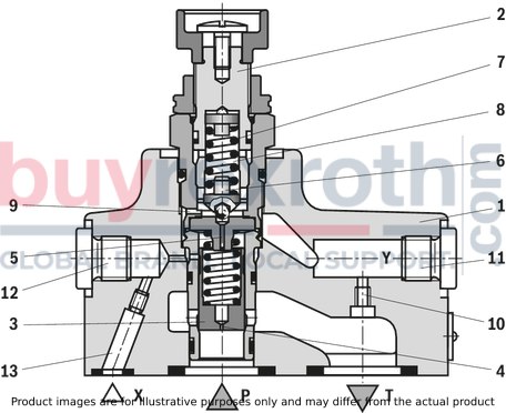
Name plate
|
2
|
Port X for remote control, optional
|
3
|
Y port for pilot oil return, external
|
4
|
Adjustment type "1"
|
5
|
Adjustment type "2"
|
6
|
Adjustment type "3"
|
7
|
Adjustment type "7"
|
8
|
Lock nut SW22, tightening torque MA = 10±5 Nm
|
9
|
Hexagon SW10
|
10
|
Hexagon SW30, tightening torque MA = 50 Nm
|
11
|
Space required to remove the key
|
12
|
Locating pin
|
13
|
Valve mounting bores
|
14
|
Pressure gauge connection
|
15
|
Identical seal rings for ports P and T
|
16
|
Seal ring for port X
|
28
|
Porting pattern according to ISO 6264-06-09-*-97
|
Valve mounting screws (separate order)
For reasons of stability, exclusively the following valve mounting screws may be used:
4 x ISO 4762 - M12 x 50 - 10.9-flZn-240h-L
with friction coefficient μtotal = 0.09 … 0.14,
tightening torque MA = 75 Nm ± 10 %,
material no. R913000283
Notice:
The tightening torques are guidelines when using screws with the specified friction coefficients and when using a manual torque wrench (tolerance ± 10 %).
Subplates (separate order) with porting pattern according to ISO 6264-06-09-*-97 see data sheet 45100.
NG25
Dimensions in mm
|
Required surface quality of the valve contact surface
|
1
|
Name plate
|
2
|
Port X for remote control, optional
|
3
|
Y port for pilot oil return, external
|
4
|
Adjustment type "1"
|
5
|
Adjustment type "2"
|
6
|
Adjustment type "3"
|
7
|
Adjustment type "7"
|
8
|
Lock nut SW22, tightening torque MA = 10±5 Nm
|
9
|
Hexagon SW10
|
10
|
Hexagon SW30, tightening torque for screw-in MA = 50 Nm
|
11
|
Space required to remove the key
|
12
|
Locating pin
|
13
|
Valve mounting bores
|
14
|
Pressure gauge connection
|
15
|
Identical seal rings for ports P and T
|
16
|
Seal ring for port X
|
29
|
Porting pattern according to ISO 6264-08-13-*-97
|
Valve mounting screws (separate order)
For reasons of stability, exclusively the following valve mounting screws may be used:
4 x ISO 4762 - M16 x 50 - 10.9-flZn-240h-L
with friction coefficient μtotal = 0.09 … 0.14,
tightening torque MA = 185 Nm ± 10 %,
material no. R913000378
Notice:
The tightening torques are guidelines when using screws with the specified friction coefficients and when using a manual torque wrench (tolerance ± 10 %).
Subplates (separate order) with porting pattern according to ISO 6264-08-13-*-97, see data sheet 45100.
Threaded connection
Dimensions in mm
1
|
Name plate
|
2
|
Port X for remote control, optional
|
3
|
Y port for pilot oil return, external
|
4
|
Adjustment type "1"
|
5
|
Adjustment type "2"
|
6
|
Adjustment type "3"
|
7
|
Adjustment type "7"
|
8
|
Lock nut SW22, tightening torque MA = 10±5 Nm
|
9
|
Hexagon SW10
|
10
|
Hexagon SW30, tightening torque MA = 50 Nm
|
11
|
Space required to remove the key
|
17
|
Grub screw is omitted with internal pilot oil return
|
18
|
Directional spool valve NG6 (data sheet 23178)
|
19
|
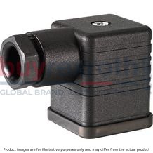
Mating connector without circuitry (separate order)
|
20
|
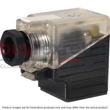
Mating connector with circuitry (separate order)
|
21
|
Dimension for valve without manual override
|
22
|
Dimension for valve with manual override "N"
|
23
|
Dimension for valve with concealed manual override "N9"
|
24
|
Housing for version "W“
|
25
|
Space required to remove the mating connector
|
26
|
Valve contact surface; port A is not bored
|
27
|
Space required to remove the solenoid coil
|
Version
|
D1
|
ØD2
|
|
mm
|
DB.10.G
|
G1/2
|
34
|
DB.15.G
|
G3/4
|
42
|
DB.20.G
|
G1
|
47
|
Mounting cavity
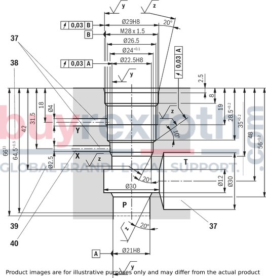
Version "XY" and type-examination tested safety valves version "Y…E"
Dimensions in mm
|
Required surface quality of the valve contact surface
|
37
|
Bore X, Y and T optionally at the circumference for version "XY"
Bore T optionally at the circumference for version "Y" (no separate bore Y required; pilot oil return via bore T)
|
38
|
Depth of fit
|
39
|
Bore Ø2.5 mm is only to be bored if required
|
40
|
Port X does not have to be bored for type-examination tested safety valves version "Y…E" as it does not have any function!
|
Version “Y”
Dimensions in mm
|
Required surface quality of the valve contact surface
|
37
|
Bore X, Y and T optionally at the circumference for version "XY"
Bore T optionally at the circumference for version "Y" (no separate bore Y required; pilot oil return via bore T)
|
38
|
Depth of fit
|