HY-CHECK VALVE M-SR 25 KE05-1X/V
Manufacturer: Bosch Rexroth
Material #: R900357445
Model : M-SR 25 KE05-1X/V
***Disclaimer: The following summary contains information gathered from various sources such as product descriptions, technical specifications and catalogs. While efforts have been made to provide accurate details, inaccuracies may occur. It is advised to verify all information by contacting Bosch Rexroth directly.***
The Bosch Rexroth M-SR 25 KE05-1X/V (R900357445) is a high-quality check valve designed for hydraulic applications, featuring a cartridge design for ease of installation and maintenance. This particular model is part of the MSR product family, which is recognized for its reliable performance in controlling fluid direction within hydraulic systems. The M-SR 25 KE05-1X/V is engineered to operate at a maximum pressure of 315 bar (4569 psi), ensuring it can handle demanding applications with ease.
With a nominal flow capacity, this check valve is capable of managing flow rates efficiently, making it suitable for a variety of hydraulic circuits. It features direct acting operation and utilizes a poppet-type spool, which contributes to its ability to provide leak-free blocking in one direction. The versatility of the M-SR 25 KE05-1X/V is further enhanced by its compatibility with multiple types of hydraulic fluids including HL, HLP, HETG, HEES, HEPG, and HFDU.
The valve's sealing material is FKM (fluoroelastomer), known for its excellent resistance to high temperatures and chemicals, ensuring durability and longevity under harsh conditions. Designed without pressure presetting, the M-SR 25 KE05-1X/V allows for various cracking pressures according to user requirements. Its compact size and capability to be installed in block designs as an angle or straight-through valve provide flexibility in system integration.
In summary, the Bosch Rexroth M-SR 25 KE05-1X/V check valve offers reliable performance with its robust design and compatibility with various hydraulic fluids. Its ability to function effectively at high pressures and flow rates makes it an essential component in maintaining efficient hydraulic operations.
| Qty | Price | Savings |
|---|---|---|
| 5+ | $0.00 USD | $0.00 USD |
This product is not available. CLICK HERE to create a support ticket for us to locate your part or a suitable replacement
This product is eligible for factory repair.
Check valve, cartridge design
Unpacked Weight: 0.3232 kg
For installation in block designs• As angle valve• As straight-through valve Leakage-free blocking in one direction Various cracking pressures, optional
| Maximum operating pressure 250 bar (3600 psi) |
| Maximum flow 300 l/min (80 gpm) |
| Data Sheet | Download Data Sheet |
| Max. pressure | 250 |
| Product family classification | Check valve, cartridge design |
| Productgroup ID | 9,10,11,12,13,14 |
| Product family type | M-SR |
| Ports number | 2 |
| Sealing material | FKM |
| Pressure setting | 0.5 |
| Product type | M-SR |
| Max. flow | 300 |
| Nominal flow | 300 |
| Pressure pre-setting | Without pressure pre-setting |
| Direct - Pilot | Direct acting |
| Product family | Check |
| Spool Poppet | Poppet type |
| Weight | 0.3232 |
| Hydraulic fluid | HL,HLP,HETG,HEES,HEPG,HFDU |
| Hydraulic fluid | HL,HLP,HETG,HEES,HEPG,HFDU |
|
01 |
02 |
03 |
04 |
|
05 |
06 |
|
07 |
08 |
|
M-SR |
|
|
|
– |
1X |
|
/ |
|
* |
|
01 |
Check valve, cartridge design |
M-SR |
|
Size |
||
|
02 |
Size 6 (not version "KE") |
6 |
|
Size 8 |
8 |
|
|
Size 10 |
10 |
|
|
Size 15 |
15 |
|
|
Size 20 |
20 |
|
|
Size 25 |
25 |
|
|
Size 30 |
30 |
|
|
Unit design |
||
|
03 |
Angle valve |
KE |
|
Straight-through valve |
KD |
|
|
Cracking pressure |
||
|
04 |
0 bar, without spring (not version "KD") |
00 |
|
0,2 bar |
02 |
|
|
0.5 bar (standard) |
05 |
|
|
1,5 bar |
15 |
|
|
3,0 bar |
30 |
|
|
5,0 bar |
50 |
|
|
05 |
Component series 10 ... 19 (10 ... 19: unchanged installation and connection dimensions) |
1X |
|
Orifice in channel B (version "KD" only) |
||
|
06 |
Without orifice |
no code |
|
Core hole M4 |
B00 |
|
|
Nozzle Ø 1.0 mm |
B10 |
|
|
Nozzle Ø 1.2 mm |
B12 |
|
|
Seal material (observe compatibility of seals with hydraulic fluid used, see "Technical data") (version "KE" only) |
||
|
07 |
NBR seals |
no code |
|
FKM seals |
V |
|
|
08 |
Further details in the plain text |
* |
general
|
Size |
6 | 8 | 10 | 15 | 20 | 25 | 30 | ||
|
Weight |
Angle valve "KE" |
kg |
- | 0.03 | 0.05 | 0.08 | 0.14 | 0.32 | 0.47 |
|
Straight-through valve "KD" |
kg |
0.05 | 0.1 | 0.2 | 0.25 | 0.3 | |||
|
Installation position |
any | ||||||||
|
Ambient temperature range |
NBR seals |
°C |
-20 … +80 | ||||||
|
FKM seals |
°C |
-20 … +80 | |||||||
|
MTTFD values according to EN ISO 13849 1) |
150 Years | ||||||||
| 1) | For further details, see data sheet 08012 and 90294 |
hydraulic
|
Size |
6 | 8 | 10 | 15 | 20 | 25 | 30 | ||
|
Maximum operating pressure |
bar |
420 | |||||||
|
Cracking pressure |
See characteristic curves | ||||||||
|
Maximum flow |
l/min |
15 | 35 | 50 | 120 | 200 | 300 | 400 | |
|
Hydraulic fluid |
see table "Hydraulic fluid" | ||||||||
|
Hydraulic fluid temperature range |
NBR seals |
°C |
-30 … +80 | ||||||
|
FKM seals |
°C |
-20 … +80 | |||||||
|
Viscosity range |
mm²/s |
2.8 … 500 | |||||||
|
Maximum admissible degree of contamination of the hydraulic fluid, cleanliness class according to ISO 4406 (c) 1) |
Class 20/18/15 | ||||||||
| 1) | The cleanliness classes specified for the components must be adhered to in hydraulic systems. Effective filtration prevents faults and simultaneously increases the life cycle of the components. For the selection of the filters, see www.boschrexroth.com/filter. |
|
Hydraulic fluid |
Classification |
Suitable sealing materials |
Standards |
Data sheet |
|
|
Mineral oils |
HL, HLP |
NBR, FKM |
DIN 51524 |
90220 |
|
|
Bio-degradable |
Insoluble in water |
HETG |
FKM |
ISO 15380 |
90221 |
|
HEES |
FKM |
||||
|
Soluble in water |
HEPG |
FKM |
ISO 15380 |
||
|
Flame-resistant |
Water-free |
HFDU (glycol base) |
FKM |
ISO 12922 |
90222 |
|
HFDU (ester base) |
FKM |
||||
|
Containing water |
HFC (Fuchs Hydrotherm 46M, Petrofer Ultra Safe 620) |
NBR |
ISO 12922 |
90223 |
|
|
Important information on hydraulic fluids: For more information and data on the use of other hydraulicfluids, please refer to the data sheets above or contact us. There may be limitations regarding the technical valve data (temperature, pressure range, life cycle, maintenance intervals, etc.). Flame-resistant - containing water: Life cycle as compared to operation with mineral oil HL, HLP 30 … 100%. Maximum hydraulic fluid temperature 60 °C |
|||||
For applications outside these parameters, please consult us!
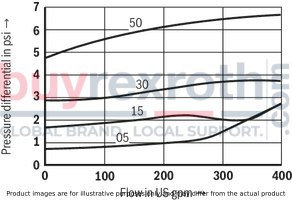
Angle valve (measured with HLP46, ϑOil = 40 ±5 °C)
Pressure differential Δp dependent on the flow qV at cracking pressure
Size 8
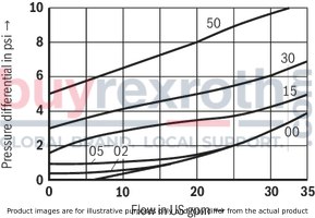
Pressure differential Δp dependent on the flow qV at cracking pressure
Size 10
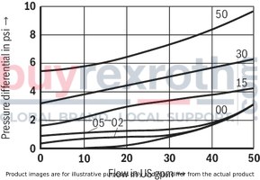
Pressure differential Δp dependent on the flow qV at cracking pressure
Size 15
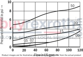
Pressure differential Δp dependent on the flow qV at cracking pressure
Size 20
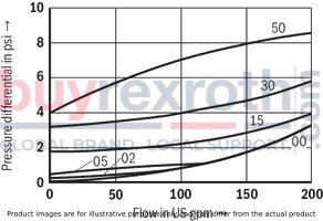
Pressure differential Δp dependent on the flow qV at cracking pressure
Size 25
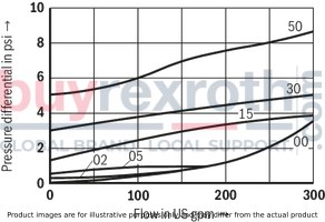
Pressure differential Δp dependent on the flow qV at cracking pressure
Size 30
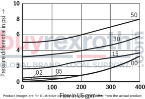
Straight-through valve (measured with HLP46, ϑOil = 40 ±5 °C)
Pressure differential Δp dependent on the flow qV at cracking pressure
Size 6
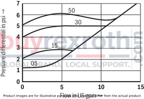
Pressure differential Δp dependent on the flow qV at cracking pressure
Size 8
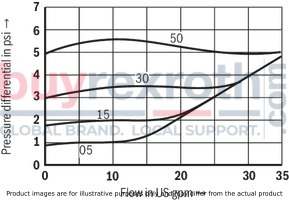
Pressure differential Δp dependent on the flow qV at cracking pressure
Size 10
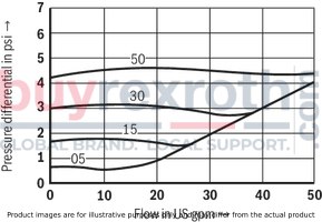
Pressure differential Δp dependent on the flow qV at cracking pressure
Size 15
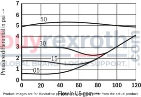
Pressure differential Δp dependent on the flow qV at cracking pressure
Size 20
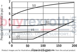
Pressure differential Δp dependent on the flow qV at cracking pressure
Size 25
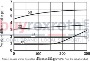
Pressure differential Δp dependent on the flow qV at cracking pressure
Size 30
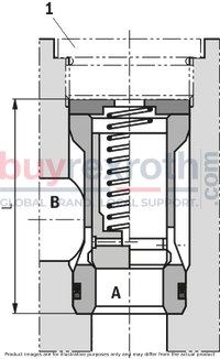
With spring

Without spring

Angle valve "KE"
Dimensions in mm
Straight-through valve "KD"
Dimensions in mm
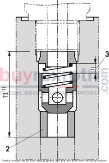
| 1) | For dimensions, see installation bores |
|
NG |
L-0,1 |
|
mm |
|
| 6 | - |
| 8 | 36.3 |
| 10 | 39.3 |
| 15 | 45.8 |
| 20 | 55.3 |
| 25 | 74.3 |
| 30 | 83.3 |
|
1 |
Plug screws, separate order, see "Accessories" |
|
2 |
Seat with -60 °C shrink-fitted |
|
3 |
Poppet stroke |
Installation bores
Installation bore: Angle valve "KE" – plug screw according to ZN 10001
Dimensions in mm
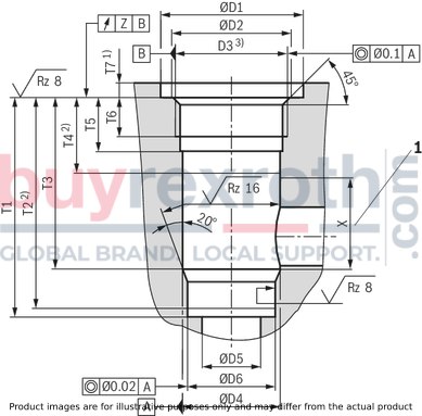
| 1) | Dimensions for countersinking the screw head. For lower installation of the installation kit, dimension T7 has to be extended accordingly. |
| 2) | Depth of fit |
| 3) | Pipe thread "G" according to ISO 228/1 |
|
1 |
Range for outlet bore |
|
NG |
pN |
ØD1 |
ØD2 |
D3 |
ØD4H8 |
ØD5 |
ØD6H7 |
T1 |
T2 |
T3 |
T4 |
T5 |
T6 |
T7 |
X |
Z |
||
|
bar |
mm |
mm |
mm |
mm |
mm |
mm |
mm |
mm |
mm |
mm |
mm |
mm |
mm |
mm |
mm |
mm |
||
| 8 | 420 | 23 | 17.1 | G3/8 | 14 | 8 | 13 | 48.5 | + 0.1 | 47.5 | 38.5 | 20 | 15 | 12 | 6 | + 0.5 | 18 | 0.05 |
| 10 | 420 | 28 | 21.4 | G1/2 | 18 | 10 | 17 | 53.5 | + 0.1 | 52.5 | 43.5 | 24 | 18 | 14 | 6 | + 0.5 | 19 | 0.05 |
| 15 | 420 | 33 | 26.8 | G3/4 | 24 | 15 | 22 | 62 | + 0.1 | 60.5 | 50 | 26 | 20.5 | 16 | 6 | + 0.5 | 24 | 0.05 |
| 20 | 420 | 41 | 33.8 | G1 | 30 | 20 | 28 | 71.5 | + 0.1 | 70 | 56.5 | 26 | 20.5 | 16 | 7 | + 0.5 | 30 | 0.05 |
| 25 | 250 | 51 | 42.5 | G1 1/4 | 38 | 25 | 36 | 90.5 | + 0.1 | 88 | 72.5 | 28 | 22 | 16 | 7 | + 0.5 | 43 | 0.1 |
| 30 | 250 | 56 | 48.5 | G1 1/2 | 44 | 30 | 42 | 99.5 | + 0.1 | 96.5 | 79.5 | 31 | 22 | 16 | 7 | + 0.5 | 48 | 0.1 |
Notice:
Plug screws, separate order, see "Accessories"
Oiling of plug screws prior to installation is recommended.
Installation bore: Angle valve – plug screw according to RN 143.28 – up to 315 bar
Dimensions in mm

| 1) | Dimensions for countersinking the screw head. For lower installation of the installation kit, dimension T7 has to be extended accordingly. |
| 2) | Depth of fit |
| 3) | Metric ISO fine thread according to DIN 13 |
|
1 |
Range for outlet bore |
|
NG |
pN |
ØD1 |
ØD2H8 |
D3 |
ØD4H8 |
ØD5 |
ØD6H7 |
T1 |
T2 |
T3 |
T4 |
T5 |
T6 |
T7 |
T8 |
X |
||||
|
bar |
mm |
mm |
mm |
mm |
mm |
mm |
mm |
mm |
mm |
mm |
mm |
mm |
mm |
mm |
mm |
mm |
mm |
mm |
||
| 25 | 315 | 56 | + 0.5 | 44 | M42 x 1,5 | 38 | 25 | 36 | 106.5 | + 0.1 | 104 | 88.5 | 45 | 39 | 33 | 5 | + 0.5 | 12 | + 0.2 | 43 |
| 30 | 315 | 62 | + 0.5 | 50 | M48 x 1,5 | 44 | 30 | 42 | 115.5 | + 0.1 | 112.5 | 95.5 | 48 | 39 | 33 | 5 | + 0.5 | 12 | + 0.2 | 48 |
Notice:
Plug screws, separate order, see "Accessories"
To be replaced in case of maintenance.
Installation bore: Angle valve – plug screw according to RN 143.28 – up to 420 bar
Dimensions in mm

| 1) | Dimensions for countersinking the screw head. For lower installation of the installation kit, dimension T7 has to be extended accordingly. |
| 2) | Depth of fit |
| 3) | Metric ISO fine thread according to DIN 13 |
|
1 |
Range for outlet bore |
|
NG |
pN |
ØD1 |
ØD2H8 |
D3 |
ØD4H8 |
ØD5 |
ØD6H7 |
ØD7 |
ØD8 |
T1 |
T2 |
T3 |
T4 |
T5 |
T6 |
T7 |
T8 |
X |
||||
|
bar |
mm |
mm |
mm |
mm |
mm |
mm |
mm |
mm |
mm |
mm |
mm |
mm |
mm |
mm |
mm |
mm |
mm |
mm |
mm |
mm |
||
| 25 | 420 | 51 | + 0.5 | 44 | M42 x 2 | 38 | 25 | 36 | 37.58 | 35.58 | 101.5 | + 0.1 | 100 | 83.5 | 40 | 34 | 27 | 6 | + 0.5 | 7.8 | + 0.2 | 43 |
| 30 | 420 | 61 | + 0.5 | 50 | M48 x 2 | 44 | 30 | 42 | 43.58 | 41.58 | 110.5 | + 0.1 | 108.5 | 90.5 | 43 | 34 | 27 | 6 | + 0.5 | 7.8 | + 0.2 | 48 |
Notice:
Plug screws, separate order, see "Accessories" Oiling of plug screws prior to installation is recommended. From an operating pressure larger 350 bar, the plug screw has to be glued by means of Loctite 243 over the complete thread circumference.Installation bore: Straight-through valve
Dimensions in mm
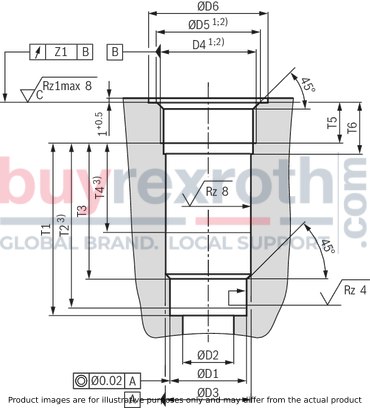
|
NG |
ØD1H7 |
ØD3H8 |
D4 1) |
ØD5 |
D4 2) |
ØD5 |
ØD6 |
T1 |
T2 3) |
T3 |
T4 3) |
T5 |
T6 |
Z |
Poppet stroke |
|||
|
mm |
mm |
mm 1) |
mm |
mm 2) |
mm |
mm |
mm |
mm |
mm |
mm |
mm |
mm |
mm |
mm |
mm |
|||
| 6 | 10 | 11 | G1/4 | 13.6 | ± 0.1 | M14 x 1,5 | 14.4 | ± 0.1 | 25 | 29.8 | - 0.1 | 27.8 | 21.8 | 19 | 12 | 16 | 0.1 | 4 |
| 8 | 13 | 14 | G3/8 | 17.1 | ± 0.1 | M18 x 1,5 | 18.4 | ± 0.1 | 28 | 32.8 | - 0.1 | 30.8 | 22.8 | 18 | 12 | 16 | 0.1 | 4 |
| 10 | 17 | 18 | G1/2 | 21.4 | ± 0.1 | M22 x 1.5 | 22.4 | ± 0.1 | 34 | 38.8 | - 0.1 | 36.8 | 28.8 | 21 | 14 | 19 | 0.1 | 4 |
| 15 | 22 | 24 | G3/4 | 26.8 | ± 0.1 | M27 x 2 | 27.4 | ± 0.1 | 42 | 48.4 | - 0.1 | 46.4 | 36.4 | 27 | 16 | 21 | 0.2 | 5 |
| 20 | 28 | 30 | G1 | 33.8 | ± 0.1 | M33 x 2 | 33.5 | ± 0.1 | 47 | 59 | - 0.1 | 57 | 44 | 29 | 18 | 24 | 0.2 | 5 |
| 25 | 36 | 38 | G1 1/4 | 42.5 | ± 0.1 | M42 x 2 | 42.5 | ± 0.1 | 58 | 73 | - 0.1 | 71 | 55 | 39 | 20 | 26 | 0.2 | 7 |
| 30 | 42 | 44 | G1 1/2 | 48.5 | ± 0.1 | M48 x 2 | 48.5 | ± 0.1 | 65 | 83 | - 0.1 | 81 | 63 | 42 | 22 | 28 | 0.2 | 7 |
| 1) | Pipe thread "G" according to ISO 228/1 |
| 2) | Metric ISO fine thread according to DIN 13 |
| 3) | Depth of fit |
Plug screw according to ZN 10001
|
Size |
Seal material |
Designation |
Material number |
Tightening torques MA ±10 % |
Buy |
Plug screw according to ZN 10001
|
Size |
Seal material |
Designation |
Material number |
Tightening torques MA ±10 % |
Buy |
|
Nm |
|||||
| 8 | NBR | ZN10001-G3/8A-N-ST | R913011602 | 55 | eShop |
| FKM | ZN10001-G3/8A-F-ST | R913011610 | eShop | ||
| 10 | NBR | ZN10001-G1/2A-N-ST | R913011603 | 80 | eShop |
| FKM | ZN10001-G1/2A-F-ST | R913011611 | eShop | ||
| 15 | NBR | ZN10001-G3/4A-N-ST | R913011604 | 135 | eShop |
| FKM | ZN10001-G1 1/2A-F-ST | R913011612 | eShop | ||
| 20 | NBR | ZN10001-G1A-N-ST | R913011605 | 225 | eShop |
| FKM | ZN10001-G1A-F-ST | R913011613 | eShop | ||
| 25 | NBR | ZN10001-G1 1/4A-N-ST | R913011606 | 360 | eShop |
| FKM | ZN10001-G1 1/4A-F-ST | R913011614 | eShop | ||
| 30 | NBR | ZN10001-G1 1/2A-N-ST | R913011607 | 400 | eShop |
| FKM | ZN10001-G1 1/2A-F-ST | R913011615 | eShop |
Plug screw according to RN 143.28 – up to 315 bar
|
Size |
Seal material |
Designation |
Material number |
Tightening torques MA ±10 % |
Buy |
|
Nm |
|||||
| 25 | NBR | M42X1,5-ST/320/NBR | R900323609 | 300 | eShop |
| FKM | M42X1,5-ST/320/FKM | R900301957 | eShop | ||
| 30 | NBR | M48X1,5-ST/320/NBR | R900323610 | 325 | eShop |
| FKM | M48X1,5-ST/320/FKM | R900301958 | eShop |
Plug screw according to RN 143.28 – up to 420 bar
|
Size |
Seal material |
Designation |
Material number |
Tightening torques MA ±10 % |
Buy |
|
Nm |
|||||
| 25 | NBR | M42X2-ST-PRECOTE85/630/NBR | R901183335 | 300 | eShop |
| FKM | M42X2-ST-PRECOTE85/630/FKM | R901253503 | eShop | ||
| 30 | NBR | M48X2-ST-PRECOTE85/630/NBR | R901183336 | 325 | eShop |
| FKM | M48X2-ST-PRECOTE85/630/FKM | R901253504 | eShop |
Related Products
R900216091
$283.00 USD
R900348143
$215.00 USD
R900424284
$774.00 USD
R900425164
$562.00 USD
R900344778
$377.00 USD


