$346.00 USD
More are expected on April 7, 2026
| Qty | Price | Savings |
|---|---|---|
| 5-24 | $337.35 USD | $8.65 USD |
| 25+ | $328.70 USD | $17.30 USD |
Status: This product is temporarily out of stock.
Qty: Delivered as early as April 7, 2026 when ordered in
Hydraulic accumulator as per Pressure Equipment Directive 97/23/EC Diaphragm material for different applications
Function, section, symbol
General information
One of the main tasks of hydraulic accumulators is e.g. to accept certain volumes of pressurized liquids of a hydraulic system and to return them to the system if required.
As the liquid is pressurized, the hydraulic accumulators are treated like pressure vessel and must be designed for the max. operating overpressure considering the acceptance standards of the country of installation.
In most hydraulic systems, hydro-pneumatic (gas-charged) accumulators with separator element are used.
The difference between bladder, piston and diaphragm type accumulators lies in the type of separator element.
Hydraulic accumulators essentially consist of a fluid section and a gas section with a gas-tight separator element. The fluid section has a connection to the hydraulic circuit. During the pressure increase, the gas is compressed and liquid accepted in the hydraulic accumulator. When the pressure decreases, the compressed gas expands and displaces the accumulated fluid into the circuit.
Diaphragm type accumulator
Diaphragm type accumulators consist of a pressure-resistant steel vessel (1) which most commonly has a spherical to cylindrical form. Inside the accumulator, there is the separator element, namely a diaphragm (2) made of an elastic, flexible material (elastomer) with the closing button (3) and the plug screw (4). They correspond to directive 97/23/EC.
Symbol

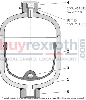
|
1 |
Containers |
|
2 |
Diaphragm |
|
3 |
Closing button |
|
4 |
Plug screw (gas filling screw) |
|
5 |
Fluid connection |
Ordering code
|
01 |
02 |
03 |
04 |
05 |
06 |
07 |
08 |
09 |
10 |
11 |
12 |
13 |
14 |
||||||
|
HAD |
- |
- |
/ |
- |
1 |
- |
- |
|
Device designation |
||
|
01 |
Diaphragm type accumulators |
HAD |
|
Nominal capacity |
||
|
02 |
See selection table |
… |
|
Maximum operating pressure |
||
|
03 |
See selection table |
… |
|
Component series |
||
|
04 |
Component series 10 ... 19 (10 ... 19: unchanged installation and connection dimensions) |
1X |
|
Component series 20 ... 29 (20 ... 29: unchanged installation and connection dimensions) |
2X |
|
|
Preload pressure |
||
|
05 |
0 to 250 bar; e.g. 10 bar |
10 |
|
Port size for hydraulic fluid 1) |
||
|
06 |
M14 x 1,5 |
Z04 |
|
M18 x 1,5 |
Z06 |
|
|
M22 x 1.5 |
Z08 |
|
|
G1/4 |
G02 |
|
|
G3/8 |
G03 |
|
|
G1/2 |
G04 |
|
|
G3/4 |
G05 |
|
|
G06 |
||
|
3/4-16 UNF |
U04 |
|
|
1 1/16-12 UNF |
U06 |
|
|
3/8 NPTF |
F02 |
|
|
1/2-14 NPTF |
F08 |
|
|
Type of mounting (oil port form) |
||
|
07 |
Mounting cavity |
A |
|
Mounting cavity with external hexagon |
C |
|
|
Screw-in stud with internal thread |
E |
|
|
Screw-in stud |
F |
|
|
Screw-in stud M45 x 1.5 with internal thread |
E5 |
|
|
Special versions on request |
||
|
Gas port form |
||
|
08 |
Standard version for 0 538 103 012 |
1 |
|
Gas valve for 0 538 103 011 |
2 |
|
|
cannot be refilled, welded on the gas side |
4 |
|
|
Bladder material |
||
|
09 |
NBR |
N |
|
ECO |
E |
|
|
IIR |
I |
|
|
FKM |
F |
|
|
Tank material |
||
|
10 |
Steel |
1 |
|
Surface of the tank inside |
||
|
11 |
Steel |
1 |
|
Galvanized steel |
2 |
|
|
Surface of the connection side |
||
|
12 |
Steel |
1 |
|
Galvanized steel |
2 |
|
|
Certification acceptance |
||
|
13 |
Acceptance according to 97/23/EC |
CE |
|
Instructions for use |
BA |
|
|
14 |
Further details in the plain text e. g. SO variant |
* |
| 1) | Other versions available upon request. |
Selection table
|
Nominal capacity |
Maximum operating pressure |
Component series |
Certification acceptance |
|
l |
bar |
||
|
0,075 |
250 |
1X |
BA |
|
0,16 |
250 |
1X |
BA |
|
0,35 |
210 |
1X |
BA |
|
0,5 |
160 |
1X |
BA |
|
250 |
2X |
||
|
0,7 |
100 |
1X |
BA |
|
180 |
1X |
||
|
250 |
1X |
||
|
350 |
2X |
||
|
1 |
200 |
1X |
BA |
|
1,4 |
140 |
1X |
CE |
|
250 |
1X |
||
|
350 |
2X |
||
|
2 |
100 |
1X |
CE |
|
250 |
1X |
||
|
350 |
2X |
||
|
2,8 |
70 |
1X |
CE |
|
250 |
1X |
||
|
350 |
1X |
||
|
3,5 |
250 |
1X |
CE |
|
350 |
1X |
general
|
Nominal capacity |
l |
0.075 | 0.16 | 0.35 | 0.5 | 0.7 | 1 | 1.4 | 2 | 2.8 | 3.5 |
|
Weight |
kg |
0.65 | 1 | 1.3 | 1.6 | 2.6 | 3.5 | 4.9 | 4 | 5.5 | 14 |
|
kg |
- | - | - | 2 | 3.2 | - | 6.2 | 9.5 | 10 | - | |
|
Design |
Diaphragm type accumulator, welded | ||||||||||
|
Installation position |
Any, preferably with the fluid connection socket at the bottom | ||||||||||
|
Mounting type |
with clamps or via stud end connectors | ||||||||||
|
Ambient temperature range 1) |
°C |
-15 … +65 | |||||||||
|
Line connection |
Screw-in thread | ||||||||||
| 1) | The admissible temperature range specified in the tank test is also decisive |
hydraulic
|
Nominal capacity |
VNenn |
l |
0.075 | 0.16 | 0.35 | 0.5 | 0.7 | 1 | 1.4 | 2 | 2.8 | 3.5 |
|
Effective gas volume |
Veff |
l |
0.075 | 0.16 | 0.32 | 0.48 | 0.75 | 1 | 1.4 | 1.95 | 2.7 | 3.5 |
|
Maximum flow |
qmax |
l/min |
10 | 10 | 40 | 40 | 40 | 40 | 40 | 60 | 60 | 60 |
|
Maximum operating pressure |
pmax |
bar |
- | - | - | - | 100 | - | - | - | 70 | - |
|
bar |
- | - | 210 | 160 | 180 | - | 140 | 100 | - | - | ||
|
bar |
250 | 250 | 207 | 207 | 250 | 200 | 250 | 250 | 250 | 250 | ||
|
bar |
- | - | - | 250 | 350 | - | 350 | 350 | 350 | 350 | ||
|
Maximum admissible pressure fluctuation range |
Δpdyn |
bar |
- | - | - | - | 93 | - | - | - | - | - |
|
bar |
- | - | 90 | 90 | 93 | - | 80 | 65 | - | - | ||
|
bar |
150 | 120 | 120 | 120 | 140 | 115 | 140 | 140 | 130 | 130 | ||
|
bar |
- | - | - | 100 | 130 | - | 130 | 130 | 130 | 130 | ||
|
Hydraulic fluid 1) |
Hydraulic oil according to DIN 51524 | |||||||||||
|
Hydraulic fluid temperature range |
NBR |
°C |
-10 … +80 1) 2) | |||||||||
|
ECO |
°C |
-35 … +80 | ||||||||||
| 1) | Other hydraulic fluids upon request. |
| 2) | The admissible temperature range specified in the tank test is also decisive |
pneumatic
|
Charging gas |
use only nitrogen! |
Usable hydraulic fluids
When selecting the accumulator design, you have to observe the following, unbinding information with regard to hydraulic fluid, bladder and/or diaphragm material and admissible temperature range.
Warranty claims cannot be derived from these recommendations. For other hydraulic fluids and temperatures, please contact us.
|
Hydraulic fluids |
Temperature range |
Material |
|
Mineral oils |
-10 … +80 °C |
NBR |
|
-35 … +80 °C |
ECO |
|
|
HFA, HFB 1) |
+5 … +50 °C |
NBR |
|
HFC |
-10 … +60 °C |
NBR, IIR |
|
HFD 2) |
-10 … +60 °C |
IIR |
|
-10 … +80 °C |
FKM |
|
|
Water 1) |
+5 … +50 °C |
NBR |
|
Diesel, heating fuel |
-10 … +50 °C |
NBR |
|
Heavy heating fuel |
-10 … +100 °C |
FKM |
|
Regular gasoline |
-10 … +40 °C |
NBR |
|
Premium gasoline |
-10 … +40 °C |
FKM |
|
Kerosene |
-10 … +40 °C |
NBR |
| 1) | Possible special version for vessel and connection parts |
| 2) | Consultation with exact specification of the hydraulic fluid |
| NBR ‒ Acrylonitrile-butadiene rubber (Perbunan) | |
| FKM ‒ Fluorocarbon rubber | |
| IIR ‒ Butyl rubber | |
| ECO ‒ Epichlorhydrin rubber |
For applications outside these parameters, please consult us!
Calculation
Pressures
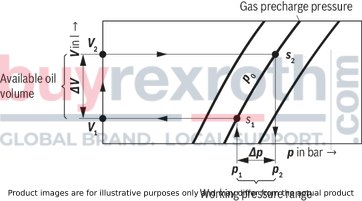
For the calculation of an accumulator, the following pressures are of significance:
p0 = gas precharge pressure (at room temperature and drained fluid chamber)
p0(t) = gas precharge pressure (at operating temperature)
p1 = minimum operating pressure
p2 = maximum operating pressure
(pm = average operating pressure)
To achieve the best possible utilization of the accumulator capacity and a long service life, it is recommended that the following values be adhered to:
p0, tmax ≈ 0,9 p1 (1)
The highest hydraulic pressure should not exceed the quadruple of the precharge pressure; otherwise, the elasticity of the diaphragm is overstressed and excessive variations in the compression result in strong heating up of the gas.
The smaller the difference between p1 and p2 the longer is the service life of the diaphragm. However, this also reduces the degree of utilization of the corresponding maximum accumulator capacity.
Diaphragm-type accumulators
p2 ≤ 4 • p0 (2)
On request
p2 ≤ 8 • p0
Note!
Filling piece in diaphragm-type accumulators
To achieve an increased pressure ratio (p0:p2 > 1:4) in the accumulator, a filling piece can be installed on the gas side of the accumulator.
This reduces the usable gas volume V1, but the diaphragm is protected against impermissible deformation.
Oil volume
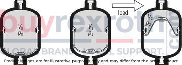
Pressures p0 … p2 determine gas volumes V0 … V2.
Here, V0 is also the nominal capacity of the accumulator.
The available oil volume V corresponds to the difference beween gas volumes V1 and V2:
ΔV ≤ V1 - V2 (3)
The gas volume, which is variable within a pressure differential, is determined by the following equations:
a) In the case of isothermal changes of state of gases, that is, when the gas buffer changes so slowly that enough time is available for a complete heat exchange between the nitrogen and its surroundings and the temperature therefore remains constant, the following is valid:
p0 • V0 = p1 • V1 = p2 • V2 (4.1)
b) In the case of an adiabatic change of state, that is, with a rapid change of the gas buffer, in which the temperature of the nitrogen changes as well, the following is valid
p0 • Vχ0 = p1 • Vχ1 = p2 • Vχ2 (4.2)
χ = ratio of the specific heat of gases (adiabatic exponent), for nitrogen = 1.4
In practice, changes in state rather follow adiabatic laws. Charging is often isothermal, discharging adiabatic.
Taking account of equations (1) and (2), ΔV is 50 % to 70 % of the nominal accumulator capacity. The following can be applied as a rule of thumb:
V0 = 1.5 … 3 x ΔV
Calculation diagram
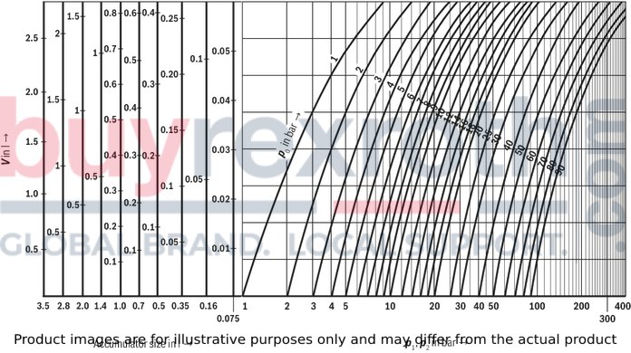
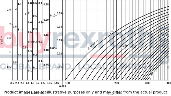
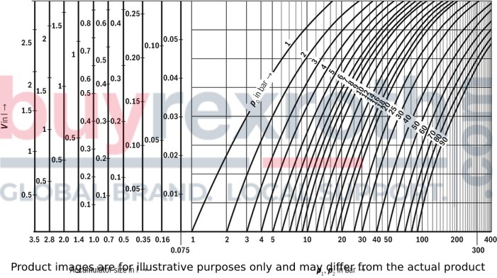
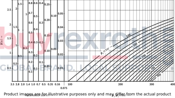
To allow a determination on the basis of a graphic representation, the formulas (4.1) and (4.2) were translated into diagrams. Depending on the task at hand, the available oil volume, the accumulator size or the pressures can be established.
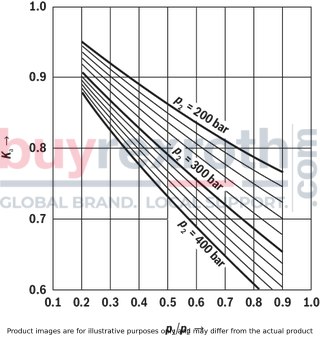
Correction factors Ki and Ka
Equations (4.1) and (4.2) are only valid for ideal gases. In the characteristics of real gases, significant deviations can be observed at operating pressures above 200 bar, which must be taken into account by applying correction factors. These are shown on the following diagrams. The correction factors which are to be multiplied by the ideal withdrawal volume ΔV are within the range of 0.6 … 1.
Application of the calculation diagrams
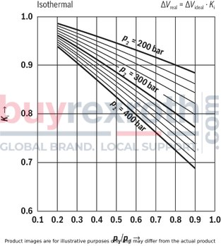
Adiabatic ΔVreal = ΔVideal x Ka
Isothermal state changes p0 = 1 … 90 bar
Isothermal state changes p0 = 100 … 300 bar
Adiabatic state changes p0 = 1 … 90 bar
Adiabatic state changes p0 = 100 … 300 bar
Application, mode of operation
Applications
Various applications exist for hydro-pneumatic accumulators:
Energy storage in order to save pump drive power in intermittent operation systems. Energy reserve for emergencies, e.g. upon failure of the hydraulic pump. Compensation of leakage losses. Impact and vibration absorption in case of periodic vibrations. Volume compensation in case of pressure and temperature changes. Suspension element for vehicles. Shock absorption with mechanical shocks.
Mode of operation
Fluids are almost incompressible and therefore cannot store pressure energy. Hydro-pneumatic Rexroth accumulators use the compressibility of a gas for fluid storage. Only neutral gases may be used. Usually “nitrogen” class 4.0.
N2 99.99 vol. %
O2 50 vpm
H2O approx. 30 vpm.
Dimensions: 70 … 250 bar
Dimensions in mm
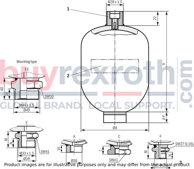
|
1 |
Gas port form „1“ |
|
2 |
Lettering |
|
Type |
Volume |
Ød |
h |
L |
M |
N |
Mass |
|
l |
mm |
mm |
mm |
mm |
mm |
kg |
|
| HAD0,075 | 0.075 | 64 | 91 | 20 | 21.5 | 12 | 0.65 |
| HAD0,16 | 0.16 | 75 | 99.5 | 20 | 24 | 12 | 1 |
| HAD0,35 | 0.35 | 92 | 114 | 22 | 33 | 18 | 1.3 |
| HAD0,5 | 0.5 | 103 | 127 | 22 | - | - | 1.6 |
| HAD0,5 | 0.5 | 106 | 130 | 20 | 27 | 12 | 2 |
| HAD0,7 | 0.7 | 121 | 144 | 22 | 33 | 18 | 2.6 |
| HAD0,7 | 0.7 | 123.6 | 144 | 22 | 33 | 18 | 3.2 |
| HAD1,0 | 1 | 136 | 158 | 22 | 33 | 18 | 3.5 |
| HAD1,4 | 1.4 | 147 | 169 | 22 | 33 | 18 | 4.9 |
| HAD1,4 | 1.4 | 152 | 173 | 22 | 33 | 18 | 6.2 |
| HAD2,0 | 2 | 144 | 218 | 22 | 33 | 18 | 4 |
| HAD2,0 | 2 | 155 | 229 | 22 | 33 | 18 | 9.5 |
| HAD2,8 | 2.8 | 160 | 247 | 21 | 33 | 18 | 5.5 |
| HAD2,8 | 2.8 | 174 | 247 | 21 | 33 | 18 | 10 |
| HAD3,5 | 3.5 | 174 | 285 | 21 | 33 | 18 | 14 |
Dimensions of standard types: 160 … 250 bar; 0,075 … 0,5 l
Dimensions in mm
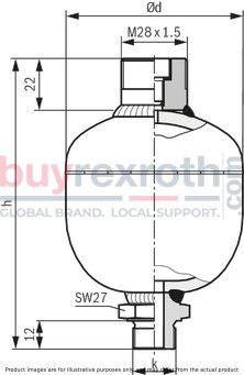
|
Ordering code/type |
Volume |
Part number |
Ød |
h |
k |
|
l |
mm |
mm |
|||
| HAD0,075-250-1X/2Z04F-1N111-BA | 0.075 | R901183242 | 65.5 | 112.5 | M14 x 1,5 |
| HAD0,16-250-1X/2Z06F-1N111-BA | 0.16 | R901183248 | 76.5 | 123.5 | M18 x 1,5 |
Dimensions in mm
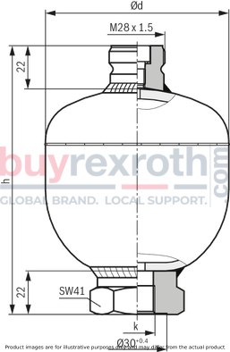
|
Ordering code/type |
Volume |
Part number |
Ød |
h |
k |
|
l |
mm |
mm |
|||
| HAD0,35-210-1X/2Z06C-1N111-BA | 0.35 | R901183250 | 94.3 | 136 | M18 x 1,5 |
| HAD0,5-160-1X/2Z06C-1N111-BA | 0.5 | R901183251 | 104.8 | 149 | M18 x 1,5 |
| HAD0,5-250-2X/2Z06C-1N111-BA | 0.5 | R901183253 | 108.5 | 152 | M18 x 1,5 |
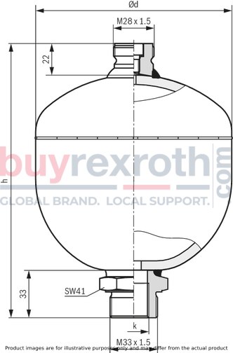
Dimensions of standard types: 100 … 250 bar; 0,7 … 1,4 l
Dimensions in mm
|
Ordering code/type |
Volume |
Part number |
Ød |
h |
k |
|
l |
mm |
mm |
|||
| HAD0,7-100-1X/2G04E-1N111-BA | 0.7 | R901164364 | 118.8 | 172 | G1/2 |
| HAD0,7-210-1X/2G04E-1N111-BA | 0.7 | R901164365 | 123.5 | 177 | G1/2 |
| HAD1,0-200-1X/2G04E-1N111-BA | 1 | R901164367 | 138.5 | 191 | G1/2 |
| HAD1,4-140-1X/2G04E-1N111-CE | 1.4 | R901164368 | 149.6 | 202 | G1/2 |
| HAD1,4-250-1X/2G04E-1N111-CE | 1.4 | R901164369 | 152 | 206 | G1/2 |
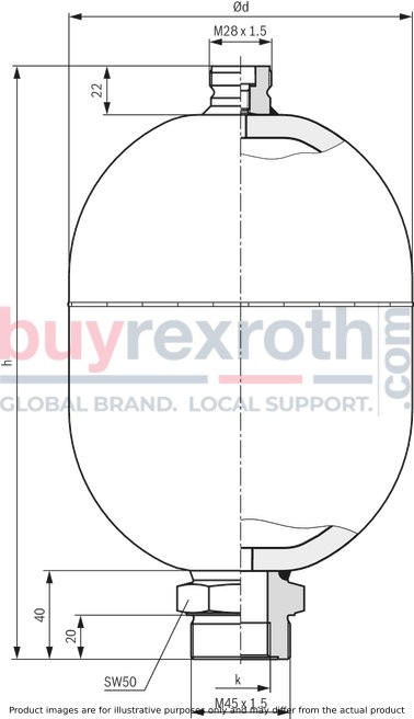
Dimensions of standard types: 100 … 250 bar; 2 … 3,5 l
Dimensions in mm
|
Ordering code/type |
Volume |
Part number |
Ød |
h |
k |
|
l |
mm |
mm |
|||
| HAD2,0-100-1X/2G05E5-1N111-CE | 2 | R901164371 | 147.2 | 258 | G3/4 |
| HAD2,0-250-1X/2G05E5-1N111-CE | 2 | R901164372 | 158.6 | 269 | G3/4 |
| HAD2,8-250-1X/2G05E5-1N111-CE | 2.8 | R901164374 | 177.5 | 286 | G3/4 |
| HAD3,5-250-1X/2G05E5-1N111-CE | 3.5 | R901164376 | 177.5 | 325 | G3/4 |
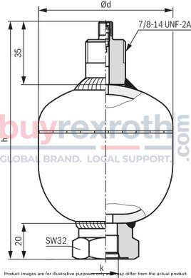
Dimensions of US standard types: 207 … 250 bar; 0,075 … 0,35 l
Dimensions in mm
|
Ordering code/type |
Volume |
Part number |
Ød |
h |
k |
|
l |
mm |
mm |
|||
| HAD0,075-250-1X/0U12C-2N111-USA | 0.075 | 0531610632 | 65.5 | 125.8 | 9/16-18 UNF-2B |
| HAD0,16-250-1X/0U12C1-2N111-USA | 0.16 | 0531600611 | 76.5 | 132.3 | 9/16-18 UNF-2B |
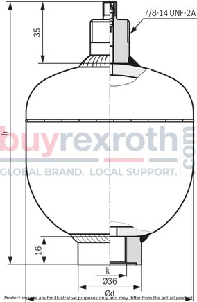
Dimensions in mm
|
Ordering code/type |
Volume |
Part number |
Ød |
h |
k |
|
l |
mm |
mm |
|||
| HAD0,35-207-1X/0U04A-2N111-USA | 0.35 | 0531601572 | 96.5 | 150.5 | 3/4-16 UNF-2B |
Dimensions in mm
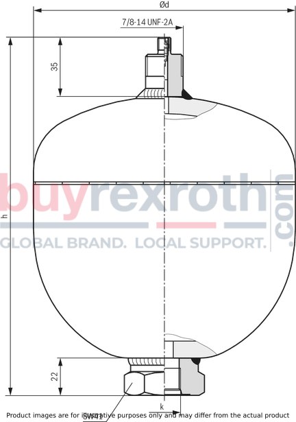
|
Ordering code/type |
Volume |
Part number |
Ød |
h |
k |
|
l |
mm |
mm |
|||
| HAD0,7-207-1X/0U04C-2N111-USA | 0.7 | 0531602588 | 128.5 | 186 | 3/4-16 UNF-2B |
| HAD1,4-207-1X/0U04C-2N111-USA | 1.4 | 0531603501 | 156.5 | 212.8 | 3/4-16 UNF-2B |
| HAD2,0-207-1X/0U04C-2N111-USA | 2 | 0531623500 | 156.5 | 265.8 | 3/4-16 UNF-2B |
| HAD2,8-207-1X/0U04C-2N111-USA | 2.8 | 0531613503 | 175.5 | 282.5 | 3/4-16 UNF-2B |
Dimensions of standard types: 350 bar; 0,7 … 2 l
Dimensions in mm
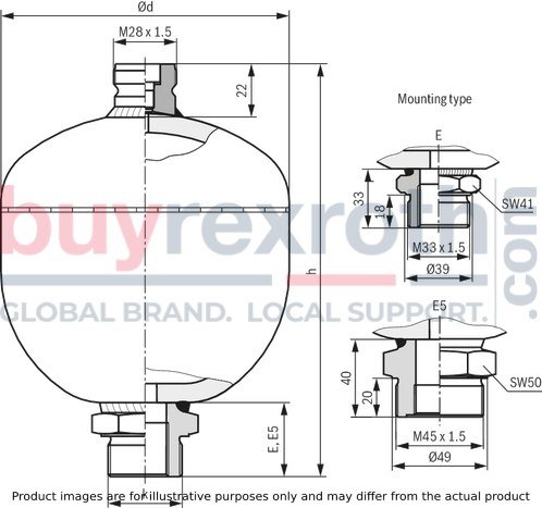
|
Ordering code/type |
Volume |
Part number |
Ød |
h |
k |
Mass |
|
l |
mm |
mm |
kg |
|||
| HAD0,7-350-2X/2G04E-1N111-BA | 0.7 | R901164366 | 128.5 | 184 | E | 4 |
| HAD1,4-350-2X/2G04E-1N111-CE | 1.4 | R901164370 | 156 | 209 | E | 7 |
| HAD2,0-350-2X/2G05E5-1N111-CE | 2 | R901164373 | 156 | 269 | E5 | 9.5 |
Dimensions of standard types: 350 bar; 2,8 and 3,5 l
Dimensions in mm
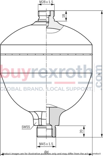
|
Ordering code/type |
Volume |
Part number |
Ød |
h |
Mass |
|
l |
mm |
mm |
kg |
||
| HAD2,8-350-1X/2G05E5-1N111-CE | 2.8 | R901164375 | 180 | 285 | 13 |
| HAD3,5-350-1X/2G05E5-1N111-CE | 3.5 | R901164377 | 180 | 325 | 16 |
Commissioning, maintenance
Notice for commissioning
Charging pressure
Diaphragm accumulators are usually delivered in condition ready for operation. The charging pressure (p0) is engraved on the accumulator housing.
Charging gas
Hydraulic accumulators must only be filled with nitrogen of class 4.0, pure N2 content of 99.99 vol. %.
Admissible operating temperature
In “standard version”, Bosch Rexroth hydraulic accumulators are suitable for operating temperatures of –10 … +80 °C. Please contact us for deviating temperatures.
Installation position
Diaphragm accumulators may be installed in any installation position. Above the gas valve, an installation space of 200 mm must be provided for testing and charging devices.
Fastening
When mounting the accumulator, make sure that possible forces, such as the ones created by vibrations or acceleration specific for that application, are absorbed safely. When using several mounting points, avoid stress caused by operational, elastic deformations or temperature expansions.
Bosch Rexroth offers corresponding holding clamps (see “Accessories”).
Charging the accumulator
Use the Bosch Rexroth charging and test device to charge the accumulator (see “Accessories”). Refer to the information given in operating instructions 1 539 929 010 for details.
Notice
The pre-filling pressure will change with the gas temperature. After charging or draining nitrogen, wait with the check of the gas pressure until the temperature balance has been completed.
Maintenance
General information
After having been charged with gas, Bosch Rexroth accumulators are almost maintenance-free.
To guarantee a fault-free operation and a long life cycle, however, the following maintenance work must be carried out:
Inspection of the preset gas pressure Inspection of the safety equipment, fittings Inspection of the line connections Inspection of accumulator fixation.
Inspection of the gas filling pressure
Test intervals
After commissioning the accumulator, the charging pressure must be checked at least once in the first week. If no gas losses are detected, inspect for the second time after 3 months. If no pressure change could be determined again, annual inspections are sufficient.
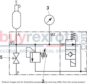
Measurements on the fluid side
Connect pressure gauge via the line with the accumulator. Alternatively, connect the pressure gauge directly to the bleed port.
Procedure:
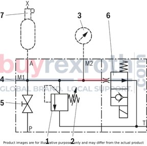
Fill the accumulator with hydraulic fluid. Close the shut-off device (5). Drain the hydraulic fluid slowly (temperature balance) by opening the safety valve (2). Observe the pressure gauge (3) during the draining process. As soon as the charging pressure has been reached in the accumulator, the pointer drops to zero abruptly.If variations are measured, check whether:
pipelines, fittings are not leaking. Whether they can be attributed to different ambient or gas temperatures.Only when no error can be determined at this point, the accumulator needs to be checked.
Adapter for size 20 blocks
Connection A (accumulator)
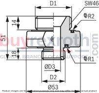
|
Accumulators |
Block |
|
|
|
D1 |
D2 |
ØD3 |
Part number |
|
mm |
|||
| M22 x 1.5 | M33 x 2 | 12 | 1 533 359 012 |
| M18 x 1,5 | 8 | 1 533 359 013 | |
| G1/2 ISO 228 | 1 533 359 034 |
Holding clamps, selection table
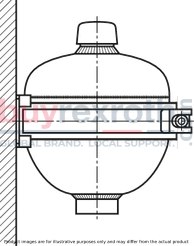
|
Type |
Clamp type |
Part number |
|
HAD0,075 |
HY/VGBKS 62– 65 |
1 551 316 024 |
|
HAD0,35 |
HY/VGBKS 92–97 |
1 531 316 017 |
|
HAD0,50 |
HY/VGBKS 101–111 |
1 531 316 018 |
|
HAD0,75 |
HY/VGBKS 119–128 |
1 531 316 015 |
|
HAD0,7 |
HY/VGBKS 128–136 |
R901073992 |
|
HAD1,0 |
HY/VGBKS 135–145 |
1 531 316 019 |
|
HAD1,4 |
HY/VGBKS 145–155 |
1 531 316 016 |
|
HAD2,0/100 |
HY/VGBKS 135–145 |
1 531 316 019 |
|
HAD2,0/250 |
HY/VGBKS 145–155 |
1 531 316 016 |
|
HAD2,8/70 |
HY/VGBKS 160–170 |
1 531 316 022 |
|
HAD2,8–3,5 |
HY/VGBKS 170–180 |
1 531 316 020 |
Charging and test device

|
Test case, complete |
Part number |
|
|
Bladder |
0 538 103 011 |
|
|
Diaphragm |
0 538 103 012 |
|
|
Bladder and diaphragm consisting of: |
0 538 103 014 |
|
|
Case |
R901070141 |
|
|
Charging and test valve |
Bladder |
0 538 103 005 |
|
Diaphragm |
0 538 103 006 |
|
|
Pressure gauge 0 … 250 bar |
1 537 231 001 |
|
|
Hose l = 2,5 m with adapter piece form "D" |
1 530 712 005 |
|
|
Accessory parts to be ordered separately |
Part number |
|
Pressure gauge 0 … 25 bar |
R900033955 |
|
Pressure gauge 0 … 60 bar |
1537231002 |
|
Pressure gauge 0 … 400 bar |
1537231005 |
|
Adapter piece |
|
|
Form "F" |
1533391010 |
|
Form "GB" |
1533391011 |
|
Form "USA" |
1533391012 |
|
Form "KR" |
1533391013 |
|
Form "J" |
1533391014 |
|
Form "RUS" |
1533391015 |
|
Hose l = 5 m with transition socket form “D” |
1530712006 |
Dimensions of charging and test valve
1 valve body with check valve, discharge valve, pressure gauge connection, and gas hose connection.
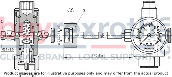
|
1 |
Spare part, Material no. 1 537 410 065 |
|
2 |
Adapter see "Adapter from nitrogen bottle..." |
Adapter for nitrogen bottle to cap nut
Dimensions in mm
Material no. 1533391010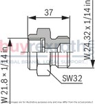
|
Material no. R900216133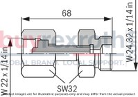
|
Material no. 1533391013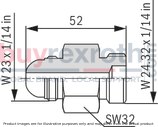
|
Material no. 1533391011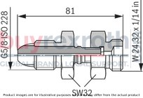
|
Material no. 1533391012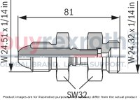
|
Material no. 1533391015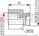
|
Adapter for nitrogen bottle to cap nut
Dimensions in inches
Material no. 1533391010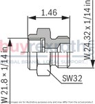
|
Material no. R900216133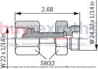
|
Material no. 1533391013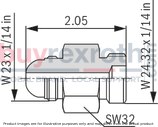
|
Material no. 1533391011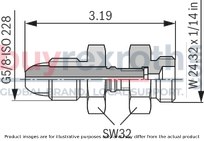
|
Material no. 1533391012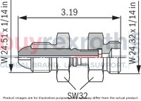
|
Material no. 1533391015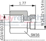
|
|
Country |
Part number |
|||||
|
1533391010 |
1533391011 |
1533391012 |
R900216133 |
1533391013 |
1533391015 |
|
|
Brazil |
x |
|||||
|
Bulgaria |
x |
|||||
|
France |
x |
|||||
|
Greece |
x |
|||||
|
Great Britain |
x |
|||||
|
India |
x |
|||||
|
Japan |
x |
|||||
|
Canada |
x |
|||||
|
Korea North |
x |
|||||
|
Korea South |
x |
|||||
|
Malaysia |
x |
|||||
|
Romania |
x |
|||||
|
Russia |
x |
|||||
|
Spain |
x |
|||||
|
Saudi Arabia |
x |
|||||
|
Singapore |
x |
|||||
|
Turkey |
x |
|||||
|
USA |
x |
|||||
|
Other countries on request. |
||||||
Safety instructions for hydraulic accumulators
For hydraulic accumulators, the regulations applicable at the place of installation prior to commissioning and during operation have to be observed.
The machine end-user will have sole responsibility for complying with existing provisions.
General information for hydraulic accumulators in hydraulic systems can be found in EN 982.
Keep all documents included in the delivery in a safe place; they will be required by the expert in recurring tests.
Warning!
Do not perform welding and soldering or any other mechanical works at the accumulator tank!
Explosion hazard due to welding and soldering works! Danger of bursting and loss of the operating permit in case of mechanical processing!
Do not charge hydraulic accumulators with oxygen or air. Explosion hazard!
Before working at hydraulic systems, depressurize the system and secure it against restarting!
Improper assembly may result in serious accidents!
The accumulator may only be commissioned by qualified personnel.
Safety equipment
In the Federal Republic of Germany, equipment, place of installation and operation of hydraulic accumulators are regulated by the “Technical rules Pressure vessels” (TRB). They require the following safety equipment:
1 Equipment against excessive pressure (type-examination tested)
2 Discharge device
3 Pressure measurement device
4 Test pressure gauge connection
5 Shut-off device
Option:
6 Electro-magnetically operated discharge device
7 Safety equipment against excessive temperature
This safety equipment is combined in a compact Bosch Rexroth safety and shut-off block.
Legal provisions
Hydraulic accumulators are pressure vessels and subject to the application national provisions and/or regulations valid at the place of installation. In Germany, the Ordinance on Industrial Safety and Health (BetrSichV) applies.
Special regulations are to be observed in shipbuilding, aircraft construction, mining, etc.
Design, production and testing are effected according to the data sheets according to AD 2000. Installation, equipment and operation are regulated by the "Technical rules Pressure vessels" (TRB).
Tank classes and tests in Germany
According to this German ordinance, pressure vessels are classified into categories according to their content in l , the admissible operating overpressure in bar and the pressure content product p x l . Depending on the category, tests are prescribed.
The following table provides an overview:
|
Vessel class |
Initial test at the manufacturer‘s end |
Acceptance test at the operator‘s end |
Recurring inspections |
||
|
Internal |
Pressure |
External |
|||
|
II p > 25 bar; p • L ≤ 200 |
◯ |
◯ |
◯ |
◯ |
◯ |
|
III p > 1 bar; p • L > 200 ≤ 1.000 |
X |
X |
◯ |
◯ |
◯ |
|
IV p > 1 bar; p • L > 1.000 |
X |
X |
X 51) / 102) |
X 101) |
X 21) |
| 1) | Years |
| 2) | Years with non-corroding fluids |
| X by expert | |
| ◯ by specialist | |
| Notice! | |
| All tank classes are to be secured by means of a pressure relief valve according to directive 97/23/EC. |
Related Products
R978712100
$578.00 USD
R987413357
$226.00 USD
R901435305
$2,505.10 USD
R901463743
$246.00 USD
R901445989
$343.38 USD


