


Manufacturer: Bosch Rexroth
Material #: R901458409
Model : 4WE6J5X/BG24NVP1Z2
***Disclaimer: The following summary contains information gathered from various sources such as product descriptions, technical specifications and catalogs. While efforts have been made to provide accurate details, inaccuracies may occur. It is advised to verify all information by contacting Bosch Rexroth directly.***
The Bosch Rexroth 4WE6J5X/BG24NVP1Z2 (R901458409) is a highly sophisticated directional spool valve designed to manage the start, stop, and direction of fluid flow within a hydraulic system. This model features a housing, one or two solenoids, a control spool, and one or two return springs to ensure smooth operation. The control spool operates under the influence of wet-pin solenoids immersed in hydraulic fluid, which guarantees responsive and precise control.
When de-energized, the control spool remains in its central or initial position due to the return springs. However, upon activation of the solenoids, the plunger exerts force on the control spool, transitioning it from its rest position to an active end position that alters the direction of flow between ports. The valve also includes a manual override feature that permits adjustment of the control spool without solenoid energization.
This particular model is equipped with two spool positions and two solenoids but does not have a spring return or detent in its de-energized state. For applications requiring constant positioning of the spool without continuous power supply, this valve can be configured with an impulse spool and detent option.
The 4WE6J5X/BG24NVP1Z2 is designed for use in potentially explosive atmospheres as per EU Explosion Protection Directive with ratings Ex ib I Mb and Ex ib II C T Gb according to EN standards. It supports maximum operating pressures up to bar and can handle maximum flow rates of l/min. The porting pattern adheres to ISO standards and it offers flexibility with electrical connections through either individual connection or piping connection NPT options. Additionally, it comes with a throttle insert for situations where operating conditions produce flows exceeding the valve's performance limit during switching processes.
$2,557.00 USD
Availability: 8 In Stock
Note: Sales tax, shipping, and applicable tariffs will be calculated at checkout.| Qty | Price | Savings |
|---|---|---|
| 5-24 | $2,493.07 USD | $63.93 USD |
| 25+ | $2,429.15 USD | $127.85 USD |
Qty: Delivered as early as April 10, 2026 when ordered in
This product is eligible for factory repair.
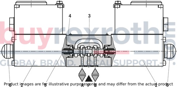
Directional valves of type WE are solenoid-actuated directional spool valves. They control the start, stop and direction of a flow.
The directional valves basically consist of the housing (1), one or two solenoids (2), the control spool (3), and one or two return springs (4).
In the de-energized condition, the control spool (3) is held in the central position or in the initial position by the return springs (4) (except for impulse spools). The control spool (3) is actuated by wet-pin solenoids in hydraulic fluid (2).
To ensure proper functioning, make sure that the pressure chamber of the solenoid is filled with hydraulic fluid.
The force of the solenoid (2) acts via the plunger (5) on the control spool (3) and pushes the latter from its rest position to the required end position. This enables the necessary direction of flow from P → A and B → T or P → B and A → T.
After de-excitation of the solenoid (2), the return spring (4) pushes the control spool (3) back to its rest position.
A manual override (6) allows control spool (3) to be moved without solenoid energization.
Without spring return “O” (only possible with symbol D)
This version is a directional valve with two spool positions and two solenoids without detent. In the de-energized condition, there is no defined spool position.
Without spring return, with detent “OF" (Impulse spool, only possible with symbol D)
This version is a directional valve with two spool positions, two solenoids and one detent.
It alternately locks the two spool positions and the solenoid therefore does not need to be permanently energized.
Notice:
For design reasons, internal leakage, which may increase over the life cycle, is inherent to the valves.
Type 4WE 6 E5X/.B..NVP1Z2
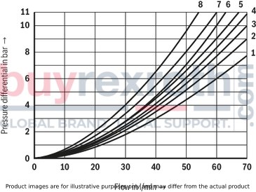
Throttle insert "...B"
The use of a throttle insert is required when, due to prevailing operating conditions, flows occur during the switching processes, which exceed the performance limit of the valve.
(measured with HLP46, ϑOil = 40 °C ±5 °C)
Δp-qV characteristic curves
|
Symbol |
Direction of flow |
|||||
|
P – A |
P – B |
A – T |
B – T |
B – A |
P – T |
|
|
D, Y |
5 |
5 |
3 |
3 |
– |
– |
|
E |
3 |
3 |
1 |
1 |
– |
– |
|
J |
1 |
1 |
2 |
1 |
– |
– |
|
G |
6 |
6 |
9 |
9 |
– |
8 |
|
C |
3 |
3 |
5 |
3 |
– |
– |
|
H |
2 |
1 |
2 |
2 |
– |
– |
|
T |
8 |
8 |
4 |
4 |
– |
– |
| Other symbols upon request |
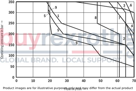
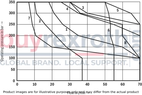
Performance limits (measured with HLP46, ϑOil = 40 °C ± 5 °C)
Notice:
The specified performance limits are valid for use with two directions of flow (e. g. from P → A and simultaneous return flow from B → T).
Due to the flow forces acting within the valves, the admissible performance limit may be considerably lower with only one direction of flow (e. g. from P → A while port B is blocked).
In such cases, please consult us.
The performance limits were determined when the solenoids were at operating temperature, at 10 % undervoltage and without tank preloading.
Direct voltage "G24"
|
Characteristic curve |
Symbol |
|
1 |
J |
|
2 |
G |
|
3 |
E |
|
4 |
D |
|
5 |
C |
|
6 |
H |
|
7 |
Y |
|
8 |
D/OF |
|
9 |
T |
AC voltage “W120R”
|
Characteristic curve |
Symbol |
|
1 |
J |
|
2 |
G |
|
3 |
E |
|
4 |
D |
|
5 |
C |
|
6 |
H |
|
7 |
Y |
|
8 |
D/OF |
Symbols

| 1) |
Example: Symbol E with spool position "a" ordering code ..EA.. |
Notices:
Representation according to DIN ISO 1219-1.
Hydraulic interim positions are shown by dashes.
Circuit diagram
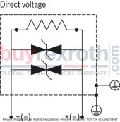
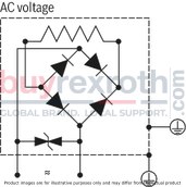
The FM-tested valve solenoid of the valve is equipped with a connection compartment and an NPT connection thread (NPT 1/2") for pipelines.
The connection is polarity-independent.
Notice:
When establishing the electrical connection, the protective grounding conductor (PE) has to be connected properly.
Connectable operating voltage conductors and protective grounding conductors
|
Function |
Maximum connectable line cross-section |
|
Terminal area, rated connection (min. 0.13 mm2) |
2.5 mm2 |
|
Conductor connection cross-section AWG (min. AWG 26) |
AWG 14 |
|
Single-wire, min. H05(07) V-U 0.13 mm2 |
2.5 mm2 |
|
Finely stranded, min. H05(07) V-K 0.13 mm2 |
2.5 mm2 |
|
Wire end ferrule with collar DIN 46 228/4 (min. 0.25 mm2) |
1.5 mm2 |
|
Wire end ferrule according to DIN 46 228/1 (min. 0.25 mm2) |
1.5 mm2 |
Connection line
|
Line type |
non-armored cables and lines (outer sheath sealing) | |
|
Temperature range |
°C |
-20 … ≥ +110 |
Over-current fuse and switch-off voltage peaks
|
Voltage data in the valve type code |
Nominal voltage valve solenoid |
Rated current valve solenoid |
Recommended pre-fuse characteristic: medium time-lag according to DIN 41571 |
Maximum voltage value when switching off |
Rated current |
Interference protection circuit |
|
G24 |
24 V DC |
0.899 A DC |
100 mA |
–36 V |
1.65 A |
Suppressor diode bi-directional |
|
W120R |
120 V AC |
0.221 A DC |
200 mA |
– |
0.384 A |
Bridge rectifier 1000 V |
Notice:
Corresponding to the rated current, a fuse according to DIN 41571 and EN / IEC 60127 has to be connected upstream of every valve solenoid (max. 3 x IG).
The shut-off threshold of the fuse has to match the prospective short-circuit current of the supply source.
The prospective short-circuit current of the supply source may amount to a maximum of 1500 A.
This fuse may only be installed outside the potentially explosive area or must be of an explosion-proof design.
When inductivities are switched off, voltage peaks result which may cause faults in the connected control electronics.
The voltage peak must be damped by a suitable external circuitry. We recommend a circuitry with a suppressor diode with a limitation voltage of approx. 50 V.
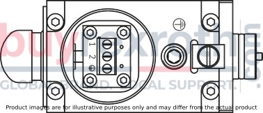
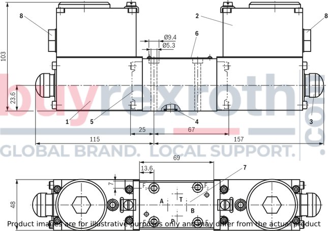
Dimensions in mm

|
|
Required surface quality of the valve contact surface |
|
1 |
Solenoid |
|
2 |
Terminal box |
|
3 |
Manual override "N" |
|
4 |
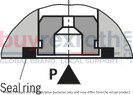
Identical seal rings for ports P, A, B, T |
|
5 |
Cap for valves with one solenoid |
|
6 |
Name plate |
|
7 |
Porting pattern according to ISO 4401-03-02-0-05 (with locating hole for locking pin ISO 8752-3x8-St, material no. R900005694, separate order) |
|
8 |
Piping connection NPT 1/2” |
Valve mounting screws (separate order)
For reasons of stability, use exclusively the following valve mounting screws:
4 hexagon socket head cap screws
ISO 4762 - M5 x 50 - 10.9-CM-Fe-ZnNi-5-Cn-T0-H-B
(friction coefficient μtotal = 0.09 … 0.14);
material no. R913043758
Subplates (separate order) with porting pattern according to ISO 4401-03-02-0-05 , see data sheet 45100.
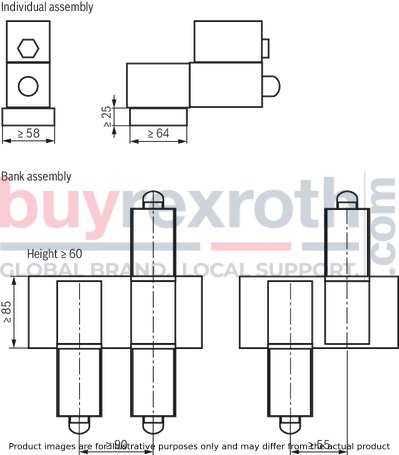
Installation conditions (dimensions in mm)
|
Single assembly |
Bank assembly |
|
|
Subplate dimensions |
Minimum dimensions: |
Minimum cross-section: |
|
Thermal conductivity of the subplate (EN-GJS-500-7) |
≥ 38 W/mK |
|
|
Minimum distance between the longitudinal valve axes |
see schematic diagram below |
|
Schematic diagram
Dimensions in mm
Notice:
Observe the "Special application conditions for safe application" see technical data.
Related Products
R901458466
$2,338.00 USD
R901458467
$2,557.00 USD
R901479320
$2,475.00 USD
R901460507
$2,557.00 USD
R901459598
$2,030.00 USD


