FLOAT SWITCH ABZMS-41-1X/1200/M2/DC-K24
Manufacturer: Bosch Rexroth
Material #: R901269289
Model : ABZMS-41-2X/1200/M2/DC-K24
***Disclaimer: The following summary contains information gathered from various sources such as product descriptions, technical specifications and catalogs. While efforts have been made to provide accurate details, inaccuracies may occur. It is advised to verify all information by contacting Bosch Rexroth directly.***
The Bosch Rexroth ABZMS-41-1X/1200/M2/DC-K24 (R901269289) is a sophisticated float switch designed for precise fluid level control in hydraulic power unit tanks. This device operates by using a float that moves with the fluid level, activating switching contacts to manage the system's operation. The model boasts two switching contacts with adjustable switching points, ensuring versatile application and customization to specific requirements.
The ABZMS-41-1X/1200/M2/DC-K24 is capable of handling maximum pressures with ease, and it features an electrical connection via a Connector pole, M12 standard. The inclusion of surge protection enhances the durability and longevity of the device in challenging environments. A clear display is integrated into the unit for easy monitoring and setup, while its compatibility with various hydraulic fluids such as HLP, HFAE, HFC, HFDR, HFDU, HETG, HEES, and HEPG makes it highly adaptable.
This model also stands out due to its resistance measuring chain for continuous level recording and an optional temperature sensor for monitoring fluid temperature. It provides a supply voltage range up to 30 VDC and can be ordered in various lengths to suit different tank sizes. With an output signal comprising two switching outputs and a weight of 0.7 kg, this float switch is both functional and manageable.
Furthermore, the ABZMS-41-1X/1200/M2/DC-K24 includes advanced features like adjustable PNP switching outputs and programmable alarm conditions displayed via integrated LEDs. Its microprocessor-controlled display unit allows for straightforward menu navigation and parameter setting through pushbuttons.
Overall, the Bosch Rexroth ABZMS-41-1X/1200/M2/DC-K24 float switch represents a reliable solution for maintaining accurate fluid levels in hydraulic systems while providing ease of use through its user-friendly interface and robust construction.
$950.00 USD
Availability: 1 In Stock
Qty: Delivered as early as January 28, 2026 when ordered in
Qty: Delivered as early as July 16, 2026 when ordered in
Float switch
Unpacked Weight: 3.28 kg
Float switches are switching devices operated by a float moved by fluid. These are used to control fluid levels in power unit tanks.
Three series are available:
Float switches typeABZMS…M with a maximum of four adjustable switching contacts normally closed contact/ normally open contact or a maximum of three switching contacts and optionally fixedly set temperature contact as normally closed contact for 60 °C, 70 °C or 80 °C Float switches type ABZMS…RTA with resistance measuring chain (level) and resistance thermometer (temperature) with analog output from 4 to 20 mA. Float switches type ABZMS…D with resistance measuring chain and resistance thermometer as with type ABZMS...RTA and additional display and control unit for level and temperature setting.Level function
Level contacts:
The sliding tubes contain the adjustable reed contacts (normally closed contact and normally open contact) that are switched by the permanent magnets installed in the float.
If with decreasing oil level, the float reaches the switching points, the contacts are magnetically operated. The spool positions of the contacts are maintained until the float passes the switching points once again due to the increasing oil level.
The switching points can be adjusted in the device.
Rotating the contacts by 180° changes the switching function; the normally closed contact type becomes a normally open contact or vice versa.
Resistance measuring chain:
The sliding tube contains the resistance measuring chain (contact distance 5 mm / resolution) for the continuous recording of the filling level height. If the individual reed contact is switched (closed) by the permanent magnet located in the float, a resistance will in each case be activated.
The added resistance value is converted by a transformer into 4 … 20 mA.
Temperature function
Temperature contact:
At the lowest point within the sliding tube, the bi-metal temperature contacts are attached to the circuit board and secured by means of a shrinkable tubing (the same procedure is used with the versions with PT 100 temperature sensor and resistance thermometer with analog output 4 … 20 mA). If the desired temperature switching point is reached, the bi-metal contact is opened or closed.
Temperature sensor PT100:
The PT100 consists of a temperature sensor guaranteeing continuous temperature recording. In this connection, the max. cable length of [si]6 m[/si][mp]236 in[/imp] is to be observed.
Resistance thermometer with measuring transducer, output 4 … 20 mA:
The PT100 resistance thermometer with measuring transducer is also attached to the circuit board in the sliding tube. The temperature-dependent signal is converted into a linear current change from 4 … 20 mA.
Display and control unit function (version D)
The micro-processor controlled display and control unit processes the analog input signals for the analysis of the level and temperature control. Level and temperature can be set at the control unit in an easy menu navigation by means of pushbuttons and the settings can be read off at the LED display.
The display and control unit has a four-digit, red seven-segment LED display and 3 pushbuttons for the operation as well as up to 4 LEDs integrated in the front plate for the display of alarm conditions.
Apart from that, the device has four freely adjustable PNP switching outputs plus the adjustable switch-back points (version D1) and alternatively (version D2) two freely programmable PNP switching outputs and 2 x 4 … 20 mA output for the continuous measurement of oil level and temperature. The switching conditions are shown in the display.
The output 4 … 20 mA can optionally be set to 0 … 10 V, 2 … 10 V or 0 … 5 V.
Depending on the setting, the display shows the measured temperature or filling level value in the desired unit (°C, °F, L, cm, %, inch or mm). By default, the temperature display is set to °C.
During the setting and/or programming of the corresponding process parameters, the parameter values and/or the related menu items are shown in the display.
In case of energy supply failure, all input values will be stored, the max/min values can be called from a permanent memory, if necessary.
Parameterization
The menu navigation is based on the VDMA standard sheet for fluid sensors 24574-1.
The operating menu is designed hierarchically as tree structure.
That means that frequently used functions and adjustment points are quickly accessible and rarely used menu items can be found in a submenu.
Using the ▲ and ▼ keys, the corresponding parameters are set and/or the next menu item is displayed.
Using the ► key, the selected menu item is selected and/or the set parameter is accepted and stored.
The parameter may be a numerical value and a selection of functions (e.g. NO [output as normally open contact], NC [output as normally closed contact] or i1 [analog output 4 … 20 mA]).
After confirmation of a parameter or function selection by means of the ► key, the display will switch back to the current menu item. Then, you can use ▲ and ▼ to display the next menu item and ► to select it.
| Surge protection |
| Float switches are switching devices operated by a float moved by fluid. |
| Two switching contacts |
| Switching points: 800 mm /600 mm |
| Data Sheet | Download Data Sheet |
| Manual | Download Manual |
| Manual | Download Manual |
| Manual | Download Manual |
| Manual | Download Manual |
| Manual | Download Manual |
| Max. pressure | 1 |
| Output signal | 2 switching outputs |
| Supply voltage | 10...36 VDC |
| Display | yes |
| Electrical connection description | Connector, 4-pole, M12 x 1, coding A according to EN 61076-2-101 |
| Hydraulic fluid | HLP,HFA-E,HFC,HFDR,HFDU,HETG,HEES,HEPG |
| Hydraulic fluid | HLP,HFA-E,HFC,HFDR,HFDU,HETG,HEES,HEPG |
| Productgroup ID | 9,10,11,12,13,14 |
| Length | 1200 |
| Weight | 3.28 |
Ordering code
|
01 |
02 |
03 |
04 |
05 |
06 |
07 |
08 |
||||||
|
ABZM |
S |
‒ |
41 |
‒ |
1X |
/ |
/ |
/ |
‒ |
|
Power unit accessories |
||
|
01 |
Measuring devices |
ABZM |
|
02 |
Float switches |
S |
|
03 |
Version |
41 |
|
04 |
Component series 10 ... 19 (10 ... 19: unchanged installation and connection dimensions) |
1X |
|
Ordering length in mm |
||
|
05 |
L = 370 mm |
0370 |
|
L = 500 mm |
0500 |
|
|
L = 800 mm |
0800 |
|
|
L = 1000 mm |
1000 |
|
|
L = 1200 mm |
1200 |
|
|
Level and temperature measurement 1) |
||
|
06 |
Number of level contacts normally closed contact/normally open contact 2) |
|
|
1 x |
M1 |
|
|
2 x |
M2 |
|
|
3 x |
M3 |
|
|
4 x |
M4 |
|
|
Number of level contacts normally closed contact/normally open contact and temperature contact 70 °C normally closed contact 3) |
||
|
1 x |
M1-T70F |
|
|
2 x |
M2-T70F |
|
|
3 x |
M3-T70F |
|
|
Number of level contacts normally closed contact/normally open contact and temperature sensor PT100, output resistance signal Ω |
||
|
1 x |
M1-TS |
|
|
2 x |
M2-TS |
|
|
3 x |
M3-TS |
|
|
Number of level contacts normally closed contact/normally open contact and resistance thermometer, output 4 … 20 mA |
||
|
1 x |
M1-TA |
|
|
2 x |
M2-TA |
|
|
3 x |
M3-TA |
|
|
06 |
Resistance measuring chain (level) and resistance thermometer analog output 4 … 20 mA |
RTA |
|
Display and control unit with resistance measuring chain and resistance thermometer with four programmable PNP switching outputs |
D1 |
|
|
Display and control unit with resistance measuring chain and resistance thermometer with two programmable PNP switching outputs and two analog outputs 4 … 20 mA |
D2 |
|
|
Voltage |
||
|
07 |
VDC 10 … 36 |
DC |
|
VAC 10 … 230 |
AC |
|
|
Without temperature contact |
no code |
|
|
Electrical connection 4) |
||
|
08 |
Connector, 4-pole M12 x 1 (standard) |
K24 |
|
Connector 4-pole (3 + PE) DIN EN 175301-803 |
K14 |
|
|
Connector 7-pole (6 + PE) DIN EN 175201-804 |
K6 |
|
| 1) | Combination possibilities function / electrical connection |
| 2) | Pinout, see “Electrical connection” |
| 3) |
Option: Temperature contact 60 °C = T60F Temperature contact 80 °C = T80F |
| 4) | Mating connectors, separate order (see R.08006) |
| Order example: | |
| Float switch with flange connection, ordering length 370 mm, two pre-set level contacts and temperature contact, normally closed contact at 70 °C, connector K24: | |
| ABZMS-S-41-1X/0370/M2-T70/DC-K24 |
|
Function |
Voltage |
|||||
|
VDC 10-36 |
VAC 10-230 |
|||||
|
K24 |
2K24 |
K14 |
K6 |
K14 |
K6 |
|
|
M1 |
X |
‒ |
X |
X |
X |
X |
|
M2 |
X |
‒ |
X |
X |
X |
X |
|
M3 |
‒ |
‒ |
‒ |
X |
‒ |
‒ |
|
M4 |
‒ |
‒ |
‒ |
X |
‒ |
‒ |
|
M1-T70F |
‒ |
X |
X |
X |
X |
X |
|
M2-T70F |
‒ |
X |
‒ |
X |
‒ |
X |
|
M3-T70F |
‒ |
‒ |
‒ |
X |
‒ |
‒ |
|
M1-TS |
‒ |
X |
‒ |
X |
‒ |
‒ |
|
M2-TS |
‒ |
X |
‒ |
X |
‒ |
‒ |
|
M3-TS |
‒ |
‒ |
‒ |
X |
‒ |
‒ |
|
M1-TA |
‒ |
X |
‒ |
X |
‒ |
‒ |
|
M2-TA |
‒ |
X |
‒ |
X |
‒ |
‒ |
|
M3-TA |
‒ |
‒ |
‒ |
X |
‒ |
‒ |
|
RTA |
X |
‒ |
‒ |
‒ |
‒ |
‒ |
|
D1 |
‒ |
X |
‒ |
‒ |
‒ |
‒ |
|
D2 |
‒ |
X |
‒ |
‒ |
‒ |
‒ |
Resistance
|
Hydraulic fluids |
||||
|
Mineral oils |
Mineral oil |
HLP |
according to DIN 51524 |
Resistant |
|
Flame-resistant hydraulic fluids |
Emulsions |
HFA-E |
according to DIN 24320 |
|
|
Water solutions |
HFC |
according to VDMA 24317 |
||
|
Phosphoric acid esters |
HFD-R |
|||
|
Organic esters |
HFD-U |
|||
|
Fast bio-degradable hydraulic fluids |
Triglycerides (rape seed oil) |
HETG |
according to VDMA 24568 |
|
|
Synthetic esters |
HEES |
|||
|
Polyglycols |
HEPG |
|||
electrical
|
Plug-in connection |
4-pole M12 x 1 (material: metal) (K24) 4-pole (3 + PE) DIN EN 175301-803 (K14) 7-pole (6 + PE) DIN EN 175201-804 (K6) |
Reed contacts of the float switches
with connection K24, K14, K6/DC
|
Switching voltage range |
V DC |
10 … 36 |
|
Maximum switching current |
A |
0.5 |
|
Maximal contact load |
VA |
10 |
Temperature contacts of the float switches
with connection K24, K14, K6/DC
|
Switching voltage range |
V DC |
10 … 50 |
|
Maximum switching current |
A |
0.5 |
|
Maximal contact load |
VA |
10 |
|
Maximum switching cycles |
100000 | |
|
Response tolerance |
K |
± 3 |
|
Hysteresis |
K |
≤10 |
|
Maximum temperature change velocity |
K/min |
1 |
Reed contacts of the float switches
with connection K14 according to DIN EN 175301-803 / K6 according to DIN EN 175201-804/AC
|
Switching voltage range |
V AC/DC |
10 … 230 |
|
Maximum switching current |
A |
0.5 |
|
Maximal contact load |
VA |
10 |
Temperature contacts of the float switches
with connection K14 according to DIN EN 175301-803 / K6 according to DIN EN 175201-804/AC
|
Switching voltage range |
V AC/DC |
10 … 230 |
|
Maximum switching current |
A |
2.5 |
|
Maximal contact load |
VA |
100 |
|
Maximum switching cycles |
100000 | |
|
Response tolerance |
K |
± 3 |
|
Hysteresis |
K |
≤10 |
|
Maximum temperature change velocity |
K/min |
1 |
Temperature sensor Pt100
|
Sensor element |
Pt100 class B DIN EN 60751 | |
|
Temperature measuring range |
°C |
0 … 100 |
|
Accuracy |
K |
± 0.8 |
Resistance measuring chain and resistance thermometer
with connection K24 for mating connector M12 x 1; 4-pole
|
Outlet 1) |
mA |
4 … 20 |
|
Resolution resistance measuring chain |
mm |
5 |
|
Maximum load resistance |
(U ‒ 9 V) / (0.02 A) | |
|
Temperature measuring range |
°C |
0 … 100 |
| 1) | Alternatively 0 … 20, 2 … 10 or 0 … 5 V adjustable |
Display and control unit
|
Power supply |
V DC |
10 … 32 | |
|
Display range |
°C |
-20 … +120 | |
|
Alarm adjustment range |
Temperature |
°C |
0 … 100 |
|
Level |
% |
0 … 100 | |
|
l |
0 … 999 | ||
|
Switching points |
4 programmable switching outputs (2 level + 2 temperature) | ||
|
Housing design |
PA, IP65 (antistatisch) | ||
|
Current consumption upon switch-on |
more than 100 ms |
mA |
≈ 100 |
|
Current consumption during operation |
with UB 24 V |
mA |
≈50 |
|
Switching output |
|
PNP | |
|
Maximum switching power |
A |
0.5 | |
|
Operation |
3 keys | ||
For applications outside these parameters, please consult us!
With two switching contacts

With two switching contacts and one temperature contact

With resistance measuring chain/resistance thermometer

With display and control unit, resistance measuring chain/resistance thermometer

Connection versions and pin assignment
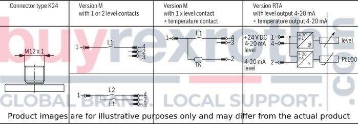


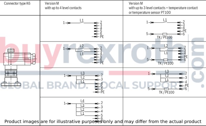
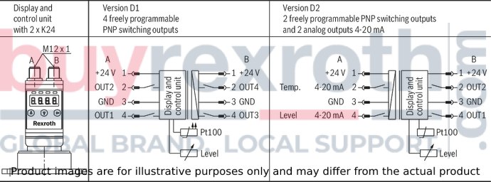
By default, the switching point L1 is set as normally closed contact and switching points L2 to L4 as normally open contact. The switching points can be adjusted in the device.
Rotating the contacts by 180° changes the switching function; the normally closed contact type becomes a normally open contact or vice versa.
Pre-set switching points Type M
|
Float switch Ordering length "L" |
Number of switching points |
||||
|
Switching points pre-set |
|||||
|
|
1 |
2 |
3 |
4 |
|
|
mm |
mm |
mm |
mm |
mm |
|
| 370 | L1 | 220 | 220 | 220 | 280 |
| L2 | - | 140 | 140 | 220 | |
| L3 | - | - | 60 | 140 | |
| L4 | - | - | - | 60 | |
| 500 | L1 | 280 | 280 | 280 | 340 |
| L2 | - | 160 | 160 | 280 | |
| L3 | - | - | 60 | 160 | |
| L4 | - | - | - | 60 | |
| 800 | L1 | 600 | 600 | 600 | 700 |
| L2 | - | 400 | 400 | 600 | |
| L3 | - | - | 200 | 400 | |
| L4 | - | - | - | 200 | |
| 1000 | L1 | 700 | 700 | 700 | 800 |
| L2 | - | 500 | 500 | 700 | |
| L3 | - | - | 200 | 500 | |
| L4 | - | - | - | 200 | |
| 1200 | L1 | 800 | 800 | 800 | 1000 |
| L2 | - | 600 | 600 | 800 | |
| L3 | - | - | 300 | 600 | |
| L4 | - | - | - | 300 | |
Dimensions:
Float switch with level and temperature contacts (version M - T..F)Float switch with resistance measuring chain and resistance thermometer (version RTA)Dimensions in mm
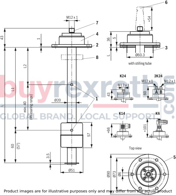
|
1 |
Switching points |
|
2 |
Flat seal |
|
3 |
Stilling tube from L = 500 mm |
|
4 |
Name plate |
|
5 |
Installation opening of the tank |
|
6 |
Mating connector for plug-in connections K24 (M12 x 1), see table "Mating connector" |
|
7 |
Connector K24; 4-pole M12 x 1 |
|
8 |
Stroke limitation ring set to 20 mA (Type RTA) |
|
Version M: L1 = min. 70 mm |
|
|
Version RTA: L1 = L ‒ min. 57 mm |
|
Dimensions: Float switch with display and control unit (version D..)
Dimensions in mm
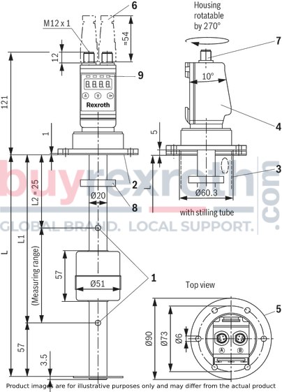
|
1 |
Measuring range 4 … 20 mA |
|
2 |
Flat seal |
|
3 |
Stilling tube from L = 500 mm |
|
4 |
Name plate |
|
5 |
Installation opening of the tank |
|
6 |
Mating connector for plug-in connections K24 (M12 x 1), see table "Mating connector" |
|
7 |
Connector K24; 4-pole M12 x 1 |
|
8 |
Stroke limitation ring set to 20 mA (Type RTA) |
|
9 |
LEDs for the display of alarm switching points |
Oil volume specification for float switch
Type M with two switching contacts
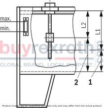
|
1 |
Residual quantity with switching point L1 |
|
2 |
Residual quantity with switching point L2 |
|
Float switch Ordering length "L" |
Switching points pre-set |
Residual hydraulic fluid volume at switching point |
|||
|
|
|
AB 40-40, AB 40-43, AB 40-44 |
|||
|
L1 |
L2 |
NG |
L1 |
L2 |
|
|
mm |
mm |
mm |
l |
l |
|
| 370 | 220 | 140 | 63 | 28 | 42 |
| 220 | 140 | 100 | 45 | 67 | |
| 220 | 140 | 160 | 74 | 100 | |
| 220 | 140 | 250 | 120 | 174 | |
| 220 | 140 | 400 | 190 | 277 | |
| 220 | 140 | 630 | 365 | 475 | |
| 220 | 140 | 800 | 460 | 600 | |
| 500 | 280 | 160 | 1000 | 490 | 740 |
| 280 | 160 | 1250 | 780 | 1030 | |
| 280 | 160 | 1600 | 990 | 1310 | |
| 280 | 160 | 2000 | 1380 | 1730 | |
Attention!
Before the commissioning, the switching contacts are to be set according to the necessary operating conditions.
Adjustment of the switching height
The contacts installed in the float switch are screwed to a contact strip within the sliding tube. They are set to the switching points according to the preceding table and can be adjusted to higher or lower values retroactively (observe minimum distances!). For adjusting the contacts, proceed as follows:
Interrupt the voltage supply Loosen the plug-in connection Loosen the screws of the connector base and pull out the connector base with the contact strip Loosen the contact from the strip and fasten it at the desired position (it can be adjusted in steps of 10 mm) Carefully insert the contact strip Fasten the connector base by means of the screws Re-establish the plug-in connection and the power connectionType RTA, D1 and D2
in tank according to AB 40-40, AB 40-43 and AB 40-44
Tank size DN100 to 800
Dimensions in mm

Tank size DN1000 to 2000
Dimensions in mm

Installation opening of the tank cover
Dimensions in mm

Standard breakthrough AB 03-39.73 similar to DIN 24557 part 2
Fastening screws:
6 HEXAGONSOCKET HEAD CAP SCREWS ISO4762-M5X18-8.8-A2P; Material no. R900202612
Assembly information
Vertical installation according to technical data (see "Technical Data") Avoid flows Do not expose the switch to strong impact and bends Avoid external magnetic fields. They may impair the function of the reed contacts.
Electrical connections:
Electrical connections may only be performed by specialists Before performing any works at electrical parts, the voltage supply is to be interrupted Tighten round connector M12 x 1 or mating connectors after connection Only plug in the round connector M12 x 1 or mating connector if it is de-energized Do not overload the contacts (see technical data) In case of inductive load, provide for a protective circuit!Normative reference
AB 24-02
Cable sets and distributors
AB 40-40
Tank made of steel, form AN, cover form C, oil pan according to WHG
AB 40-43
Tank made of steel, cover form C
AB 40-44
Tank made of steel, with frame
R.08006
Mating connectors for controlling electric valves and sensors
DIN 24320
Flame-resistant fluids - Hydraulic fluids of categories HFAE and HFAS - Properties and requirements
DIN 51524
Hydraulic fluids; hydraulic oils
DIN EN 175201-804
Detail specification - Circular connectors - Round contacts, size diameter 1.6mm, threaded coupling; German version EN 175201-804:1999
DIN EN 175301-803
Detail specification: Rectangular connectors - Flat contacts, 0,8mm thickness, locking screw not detachable; German version EN 175301-803:1999
DIN EN 60751
Industrial platinum resistance thermometers and platinum temperature sensors (IEC 60751:2008)
DIN EN 60529
Protection classes by housing
VDMA 24317
Fluid technology – Flame-resistant fluids – Technical minimum requirements
VDMA 24568
Fluid technology – Fast bio-degradable fluids – Technical minimum requirements
VDMA 24574-1
Fluid technology – Terms, menu navigation and electrical connection for fluid sensors
Mating connectors
|
For detailed information see data sheet 08006 |
|||
|
Mating connector for connector K14 according to DIN EN 175301-803 |
Mating connector for connector K6 according to DIN EN 175201-804 |
||
|
Denomination |
Part number |
Denomination |
Part number |
|
LEITUNGSDOSE 4P Z14 M SW SPEZ |
R901017012 |
LEITUNGSDOSE 7P Z6 N6RFFK |
R900002803 |
|
|
|||
|
Mating connector for connector K24 |
Mating connector for connector K24 with potted-in PVC cable, 3 m long |
||
|
Denomination |
Part number |
Denomination |
Part number |
|
LEITUNGSDOSE 4P Z24 SPEZ |
R900031155 |
LEITUNGSDOSE 4P Z24M12X1+3MSPEZ |
R900064381 |
Mating connectors for mechanical pressure switches with connector “K14”, without circuitry, standard
4P Z14
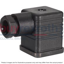
Mating connectors for mechanical pressure switches with connector “K14”, without circuitry, standard
4P Z14
For mechanical pressure switches with connector “K14”, according to EN 175301-803 and ISO 4400, 3-pole + PE, “large cubic connector”Data sheet
Spare parts & repair
Mating connectors for sensors and valves with connector “K24”, “K35” and “K72”, M12 x 1
4P Z24

Mating connectors for sensors and valves with connector “K24”, “K35” and “K72”, M12 x 1
4P Z24
For sensors and valves with connector “K24”, “K35” and “K72” Mating connectors M12, 4-pole, line cross-section 0.75 mm2Data sheet
Spare parts & repair
Mating connectors for sensors and valves with connector “K24”, “K35” and “K72”, M12 x 1, with assembled connection line
4P Z24 +
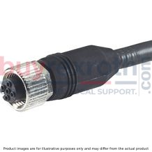
Mating connectors for sensors and valves with connector “K24”, “K35” and “K72”, M12 x 1, with assembled connection line
4P Z24 +
For sensors and valves with connector “K24”, “K35” and “K72” Mating connectors M12, 4-pole, line cross-section 0.75 mm2Data sheet
Spare parts & repair
Mating connectors for mechanical position switches, mechanical pressure switches and valves with central connection with connector “K6” and “DK6L”, 6-pole + PE
7P Z6
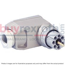
Mating connectors for mechanical position switches, mechanical pressure switches and valves with central connection with connector “K6” and “DK6L”, 6-pole + PE
7P Z6
Mating connectors for mechanical position switches, mechanical pressure switches and valves with central connection with connector “K6”Data sheet
Spare parts & repair
Use in explosive areas according to directive 94/9/EC (ATEX)
The float switches ABZMS-41 are not suitable for the use in explosive areas.
Related Products
R901550016
$6,382.00 USD
R901501193
$4,584.00 USD
R901501205
$4,584.00 USD
R901501003
$4,021.00 USD
R901483125
$5,929.00 USD


