DIRECTIONAL SPOOL VALVE H-4WMMH16E7X/6ET/B08D3
Manufacturer: Bosch Rexroth
Material #: R901257705
Model : H-4WMMH16E7X/6ET/B08D3
***Disclaimer: The following summary contains information gathered from various sources such as product descriptions, technical specifications and catalogs. While efforts have been made to provide accurate details, inaccuracies may occur. It is advised to verify all information by contacting Bosch Rexroth directly.***
The Bosch Rexroth H-4WMMH16E7X/6ET/B08D3 (R901257705) is a high-performance directional spool valve designed for controlling the start, stop, and direction of fluid flow in hydraulic systems. This particular model is a part of the WMMH series, which is known for its robust construction and reliable mechanical-hydraulic actuation. The valve features a main housing, a control spool, one or two return springs, and a mechanically actuated pilot control valve similar to the WPH type valves.
This model is equipped for subplate mounting with porting patterns according to ISO standards. It includes options for hand lever actuation and allows for various types of control such as spring centering, spring end position or hydraulic end position. The H-4WMMH16E7X/6ET/B08D3 also offers additional customization through optional features like auxiliary operating devices, switching time adjustment, preload valves in channel P of the main valve, as well as stroke setting at the main spool.
For ensuring precise control and feedback, optional inductive position switches and proximity sensors can be integrated into the design. It should be noted that any modifications to the pilot oil supply must be undertaken by authorized specialists or directly at the factory to maintain system integrity and performance.
The valve operates effectively within its maximum operating pressure and flow rate parameters. Its size and component series options provide versatility to meet various application requirements while maintaining optimal performance levels. With these capabilities, this Bosch Rexroth directional spool valve stands out as an essential component for advanced hydraulic systems requiring precise flow direction control.
$2,850.00 USD
More are expected on July 15, 2026
| Qty | Price | Savings |
|---|---|---|
| 5-24 | $2,778.75 USD | $71.25 USD |
| 25+ | $2,707.50 USD | $142.50 USD |
Status: This product is temporarily out of stock.
Qty: Delivered as early as July 15, 2026 when ordered in
This product is eligible for factory repair.
Size 16, symbol E, with manual actuation
Industrial hydraulic valve in a high performance range. Reliable switching of the oil flow direction according to hydraulic symbol
Unpacked Weight: 9.320 kg
Types of actuation: Hand lever For subplate mounting Porting pattern according to ISO 4401 Subplates according to data sheets 45054 to 45060 (separate order) Spring centering, spring end position or hydraulic end position Optional auxiliary operating device Switching time adjustment, optional Preload valve in channel P of the main valve, optional Stroke setting at main spool, optional Stroke setting and/or end position control, optional Inductive position switch and proximity sensors (contactless)
Type 4WMMH …
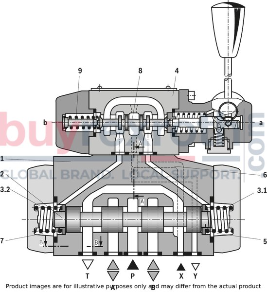
Valves of type H–.WMMH are directional spool valves with mechanical-hydraulic actuation. They control the start, stop and direction of a flow.
The directional valves basically consist of the main valve with housing (1), the main control spool (2), one or two return springs (3.1) and (3.2), as well as the pilot control valve (4).
The function of the valves corresponds to the function of valves of type WPH. The pilot control valve is, however, actuated mechanically.
Pilot oil supply
NG10
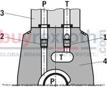
Pilot oil supply
NG16
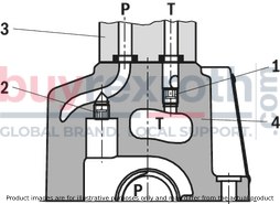
Pilot oil supply
NG25 (type 4W.H 22 .7X/…)
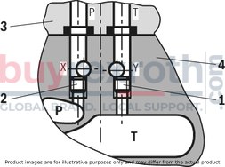
Pilot oil supply
NG25 (type 4W.H 25 .6X/…)
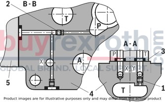
Pilot oil supply
Size 32
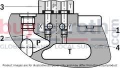
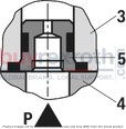
Attention!
The pilot oil supply may only be modified by authorized specialists or at the factory!
– External pilot oil supply X or return Y :
with NG10, version SO30 has to be used if sandwich plates are installed. The identification SO30 has to be used at the end of the type designation (sandwich plate). the maximum admissible operating parameters of the pilot control valve must be observed! maximum pilot pressure: please observe Technical data!– Internal pilot oil supply (version “ET” and “E”):
minimum pilot pressure: please observe Technical data! to prevent inadmissibly high pressure peaks, a “B10” throttle insert must be provided in port P of the pilot control valve. in connection with version “H-”, the “D3” pressure reducing valve (see Pressure reducing valve) has to be installed in addition.| Spool valve |
| Pilot-operated |
| Internal pilot oil supply, internal pilot oil return |
| Maximum operating pressure 280 bar |
| Component series 4X, 7X, 6X |
| Size 10 , 16 , 25 (4W.H22) , 25 (4W.H25) , 32 |
| Maximum flow 1100 l/min |
| Data Sheet | Download Data Sheet |
| Manual | Download Manual |
| Connection diagram | ISO 4401-07-07-0-05 |
| Max. pressure | 350 |
| Max. flow | 300 |
| Spool symbol | Symbol E |
| Type of connection | Subplate mounting |
| Size | 16 |
| Type of actuation | with manual actuation |
| Number of ports | 4 |
| Number of switching positions | 3 |
| Hydraulic fluid | HL,HLP,HETG |
| Seals | NBR |
| Productgroup ID | 9,10,11,12,13,14 |
| Connection diagram NFPA | NFPA T3.5.1 R2-2002 D07 |
| Size_CETOP | D07 |
| Weight | 9.320 |
|
01 |
02 |
03 |
04 |
05 |
06 |
07 |
08 |
09 |
10 |
11 |
12 |
13 |
14 |
15 |
16 |
17 |
18 |
19 |
||
|
H – |
WMMH |
/ |
6 |
/ |
* |
|
01 |
up to 350 bar 1; 2) |
H – |
|
02 |
3-way version |
3 |
|
4-way version |
4 |
|
|
Types of actuation |
||
|
03 |
mechanical-hydraulic: Hand lever |
WMMH |
|
Size |
||
|
04 |
NG10 |
10 |
|
NG16 |
16 |
|
|
NG25 (type 4W.H 22 .7X/…) |
22 |
|
|
NG25 (type 4W.H 25 .6X/…) |
25 |
|
|
Size 32 |
32 |
|
|
Spool return in the main valve |
||
|
05 |
by means of springs |
no code |
|
hydraulic 3) |
H |
|
|
06 |
Symbols; for the possible version, see "Symbols/Circuit diagrams" |
|
|
Component series |
||
|
07 |
40 to 49 – NG10 (40 to 49: unchanged installation and connection dimensions) |
4X |
|
60 to 69 – NG25 (4W.H 25.) and NG32 (60 to 69: unchanged installation and connection dimensions) |
6X |
|
|
70 to 79 – NG16 (from series 72) and NG25 (4W.H 22.) (70 to 79: unchanged installation and connection dimensions) |
7X |
|
|
Spool return in the pilot control valve with 2 spool positions only possible with spools B, C, D and hydraulic control spool return in the main valve: |
||
|
08 |
With spring return |
no code |
|
Without spring return with detent |
F |
|
|
Pilot control valve |
||
|
09 |
with mechanical, manual actuation |
6 |
|
10 |
Without manual override |
no code |
|
11 |
External pilot oil supply, external pilot oil return 1) |
no code |
|
Internal pilot oil supply, external pilot oil return 1; 2) |
E |
|
|
Pilot oil supply internal, pilot oil return internal 2) |
ET |
|
|
External pilot oil supply, internal pilot oil return 1) |
T |
|
|
12 |
without switching time adjustment |
no code |
|
Switching time adjustment as supply control |
S |
|
|
Switching time adjustment as discharge control |
S2 |
|
|
Spool position monitoring |
||
|
13 |
Without position switch |
no code |
|
Monitored spool position "a" |
QMAG24 |
|
|
Monitored spool position "b" |
QMBG24 |
|
|
Monitored spool position "a" and "b" |
QMABG24 |
|
|
Monitored rest position |
QM0G24 |
|
|
14 |
Stroke setting see stroke setting in type key table |
|
|
Throttle insert |
||
|
15 |
Without throttle insert |
no code |
|
Throttle Ø 0.8 mm |
B08 |
|
|
Throttle Ø 1.0 mm |
B10 |
|
|
Throttle Ø 1.2 mm |
B12 |
|
|
Throttle Ø 1.5 mm |
B15 |
|
|
Throttle Ø 2.0 mm |
B20 |
|
|
Throttle Ø 2.5 mm |
B25 |
|
|
preload valve (not for NG10) 4) |
||
|
16 |
without preload valve |
no code |
|
with preload valve (pö = 4.5 bar) |
P4,5 |
|
|
17 |
without pressure reducing valve |
no code |
|
with pressure reducing valve |
D3 4) |
|
|
Seal material |
||
|
18 |
NBR seals |
no code |
|
FKM seals (other seals upon request) |
V |
|
|
Observe compatibility of seals with hydraulic fluid used. |
||
|
19 |
Information in the plain text |
* |
| 1) External pilot oil supply X or return Y: | |
| – with NG10, version SO30 has to be used if sandwich plates are installed. The identification SO30 has to be used at the end of the type designation (sandwich plate). | |
| – the maximum admissible operating parameters of the pilot control valve must be observed! | |
| – observe the maximum pilot pressure! | |
| 2) Internal pilot oil supply (version “ET” and “E”): | |
| – minimum pilot pressure: please observe Technical data! | |
| – to prevent inadmissibly high pressure peaks, a “B10” throttle insert must be provided in port P of the pilot control valve (see Pilot oil supply). | |
| – in connection with version “H”, the “D3” pressure reducing valve must be installed in addition. | |
| 3) 2 spool positions (hydraulic end position): only piston C, D, Y, K ,Z | |
| 4) only in connection with throttle insert “B10” |
|
pSt |
Pilot pressure |
|
ppilot min |
Pilot pressure, minimum |
|
ptank |
Tank pressure |
|
pö |
Cracking pressure |
Preferred types and standard units are contained in the EPS (standard price list).
general
|
Size |
10 | 16 | 25 (4W.H22) | 25 (4W.H25) | 32 | ||
|
Weight (approx.) |
kg |
6.4 | 8.5 | 11.5 | 17.6 | ||
|
Switching time adjustment |
kg |
0.8 | |||||
|
Pressure reducing valve |
kg |
0.4 | |||||
|
Installation position |
any; horizontal with valves with hydraulic control spool return “H” and spool symbol B, C, D, K, Z, Y | ||||||
|
Ambient temperature range |
°C |
-30 … +50 | |||||
|
Storage temperature range |
°C |
-20 … +70 | |||||
|
Surface protection |
Valve body |
Coating, layer thickness max. 100 μm | |||||
hydraulic
|
Size |
10 | 16 | 25 (4W.H22) | 25 (4W.H25) | 32 | |||
|
Maximum operating pressure |
Port P |
bar |
350 | |||||
|
Anschluss A |
bar |
350 | ||||||
|
Port B |
bar |
350 | ||||||
|
Port T |
External pilot oil return Y |
bar |
315 | 250 | ||||
|
Internal pilot oil return Y 1) |
bar |
160 | ||||||
|
Port Y |
Pilot oil return, external |
bar |
160 | |||||
|
Hydraulic fluid 2) |
see table | |||||||
|
Hydraulic fluid temperature range |
NBR seals |
°C |
-30 … +80 | |||||
|
FKM seals |
°C |
-20 … +80 | ||||||
|
Viscosity range |
mm²/s |
2.8 … 500 | ||||||
|
Maximum admissible degree of contamination of the hydraulic fluid 3) |
Class 20/18/15 according to ISO 4406 (c) | |||||||
|
Maximum pilot pressure 4) |
bar |
250 | 210 | 250 | ||||
|
Minimum pilot pressure |
External or internal pilot oil supply X (with control spool D, K, E, J, L, M, Q, R, U, W) |
3-spool position valve, spring-centered |
bar |
10 | 14 | 12.5 | 13 | 8.5 |
|
3-spool position valve, pressure-centered |
bar |
- | 14 | - | 18 | 8.5 | ||
|
2-spool position valve with spring end position |
bar |
10 | 14 | 13 | 10 | |||
|
2-spool position valve with hydraulic end position |
bar |
7 | 14 | 8 | 5 | |||
|
Internal pilot oil supply X (with control spool C, F, G, H, P, T, V, Z, S) |
bar |
4.5 5) | 4.5 6) 7) | 4.5 7) | ||||
|
Pilot volume for switching process |
3-spool position valve, spring-centered |
cm³ |
2.04 | 5.72 | 7.64 | 14.2 | 29.4 | |
|
2-spool position valve |
from zero position in switching position “a” |
cm³ |
4.08 | 11.45 | 15.28 | 28.4 | 58.8 | |
|
from switching position “a” in zero position |
cm³ |
- | 2.9 | - | 7 | 15.1 | ||
|
from zero position in switching position “b” |
cm³ |
- | 5.72 | - | 14.15 | 29.4 | ||
|
from switching position “b” in zero position |
cm³ |
- | 2.83 | - | 5.73 | 14.4 | ||
|
Pilot flow for shortest switching time, approx. |
l/min |
35 | 45 | |||||
| 1) | As a 3-spool position valve, pressure-centered only possible if ppilot ≥ 2 x ptank + ppilot min |
| 2) | The ignition temperature of the process and operating medium used must be over the maximum solenoid surface temperature. |
| 3) | The cleanliness classes specified for the components must be adhered to in hydraulic systems. Effective filtration prevents faults and simultaneously increases the life cycle of the components. For the selection of the filters, see www.boschrexroth.com/filter. |
| 4) | Internal pilot oil supply: With a higher pilot pressure, use of a pressure reducing valve is required. In connection with version “H-”, the “D3” pressure reducing valve must be additionally provided. (If it is not used, pilot pressure = operating pressure at the port) External pilot oil return: In connection with version “H-”, compliance with the maximum pilot pressure must be ensured by appropriate measures (e. g. protection of the separate pilot oil circuit by means of a pressure relief valve)! |
| 5) | For symbols C, F, G, H, P, T, V, Z, an internal pilot oil supply is only possible if the flow from P → T in the central position (for 3-spool position valve) or while crossing the central position (for 2-spool position valve) is so large that the pressure differential of P → T reaches a value of at least 6.5 bar. |
| 6) | Spool S only for NG16 |
| 7) | For spools C, F, G,J, H, P, T, V, Z, S – by means of preload valve (not NG10) or correspondingly high flow. (Determination of the required flow, see preload valve) |
|
Hydraulic fluid |
Classification |
Suitable sealing materials |
Standards |
|
|
Mineral oil |
HL, HLP |
FKM, NBR |
DIN 51524 |
|
|
Bio-degradable |
Insoluble in water |
HEES (synthetic esters) |
FKM |
VDMA 24568 |
|
HETG (rape seed oil) |
FKM, NBR |
|||
|
Soluble in water |
HEPG (polyglycols) |
FKM |
VDMA 24568 |
|
|
Other hydraulic fluids on request |
||||
Free flow cross-sections in zero position with spools Q, V and W
|
Size |
10 | 16 | 25 (4W.H22) | 25 (4W.H25) | 32 | ||
|
Spool Q |
A – T; B – T |
mm² |
13 | 32 | 78 | 83 | 78 |
|
Spool V |
P – A |
mm² |
13 | 32 | 73 | 83 | 73 |
|
A – T; B – T |
mm² |
13 | 32 | 84 | 83 | 84 | |
|
Spool W |
A – T; B – T |
mm² |
2.4 | 6 | 10 | 14 | 20 |
Inductive position switch type QM: electrical connection
The electric connection is realized via a 4-pole mating connector (separate order) with connection thread M12 x 1.
electrical
|
Connection voltage (DC voltage) |
V |
24 | ||
|
Voltage tolerance (connection voltage) |
+30 %/-15 % | |||
|
Admissible residual ripple |
% |
≤ 10 | ||
|
Max. load capacity |
mA |
400 | ||
|
Switching outputs 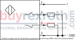
|
PNP transistor outputs, load between switching outputs and GND | |||
|
Pinout 
|
1 |
V |
24 | |
|
2, 4 |
Switching output |
mA |
400 | |
|
3 |
Earthing (GND) |
V |
0 | |
For applications outside these parameters, please consult us!
(measured with HLP46, ϑOil = 40 °C ± 5 °C)
Size 10
Δp-qV characteristic curves

|
Piston |
Spool position |
Piston |
Zero position |
|||||
|
P – A |
P – B |
A – T |
B – T |
A – T |
B – T |
P – T |
||
|
E, Y, D |
2 |
2 |
4 |
5 |
||||
|
F |
1 |
4 |
1 |
4 |
F |
3 |
– |
6 |
|
G, T |
4 |
2 |
2 |
6 |
G, T |
– |
– |
7 |
|
H, C |
4 |
4 |
1 |
4 |
H |
1 |
3 |
5 |
|
J, K |
1 |
2 |
1 |
3 |
||||
|
L |
2 |
3 |
1 |
4 |
L |
3 |
– |
– |
|
M |
4 |
4 |
3 |
4 |
||||
|
P |
4 |
1 |
3 |
4 |
P |
– |
7 |
5 |
|
Q, V, W, Z |
2 |
2 |
3 |
5 |
||||
|
R |
2 |
2 |
3 |
– |
||||
|
U |
3 |
3 |
3 |
4 |
U |
– |
4 |
– |
|
B |
2 |
2 |
– |
– |
||||
Performance limits: (measured with HLP46, ϑoil = 40 ±5 °C)
NG10
|
2-spool position valve – qV max |
|||
|
Piston |
Operating pressure pmax in bar |
||
|
200 bar |
250 bar |
315 bar |
|
|
E, J, L, M, Q, R, U, V, W, C, D, K, Z, Y |
160 l/min |
160 l/min |
160 l/min |
|
H |
160 l/min |
150 l/min |
120 l/min |
|
G, T |
160 l/min |
160 l/min |
140 l/min |
|
F, P |
160 l/min |
140 l/min |
120 l/min |
Size 16
Δp-qV characteristic curves

|
Symbol |
Spool position |
Zero position |
|||||
|
P – A |
P – B |
A – T |
B – T |
P – T |
A – T |
B – T |
|
|
D, E, Y |
1 |
1 |
3 |
3 |
|||
|
F |
1 |
2 |
5 |
5 |
4 |
3 |
– |
|
G |
4 |
1 |
5 |
5 |
7 |
– |
– |
|
C, H |
1 |
1 |
5 |
6 |
2 |
4 |
4 |
|
K, J |
2 |
2 |
6 |
6 |
– |
3 |
– |
|
L |
2 |
2 |
5 |
4 |
– |
3 |
– |
|
M |
1 |
1 |
3 |
4 |
|||
|
P |
2 |
1 |
3 |
6 |
5 |
– |
– |
|
Q |
1 |
1 |
6 |
6 |
|||
|
R |
2 |
4 |
7 |
– |
|||
|
S |
3 |
3 |
3 |
– |
9 |
– |
– |
|
T |
4 |
1 |
5 |
5 |
7 |
– |
– |
|
U |
2 |
2 |
3 |
4 |
6 |
||
|
V, Z |
1 |
1 |
6 |
6 |
10 |
8 |
8 |
|
W |
1 |
1 |
3 |
4 |
|||
Performance limits: (measured with HLP46, ϑoil = 40 ±5 °C)
NG16
|
2-spool position valve – qV max |
|||||
|
Piston |
Operating pressure pmax in bar |
||||
|
70 bar |
140 bar |
210 bar |
280 bar |
350 bar |
|
|
X external, spring end position in the main valve (with ppilotmin = 12 bar) |
|||||
|
C, D, K, Y, Z |
300 l/min |
300 l/min |
300 l/min |
300 l/min |
300 l/min |
|
X external – spring end position in the main valve 1) |
|||||
|
C |
300 l/min |
300 l/min |
300 l/min |
300 l/min |
300 l/min |
|
D, Y |
300 l/min |
270 l/min |
260 l/min |
250 l/min |
230 l/min |
|
K |
300 l/min |
250 l/min |
240 l/min |
230 l/min |
210 l/min |
|
Z |
300 l/min |
260 l/min |
190 l/min |
180 l/min |
160 l/min |
|
X external – hydraulic end position in the main valve |
|||||
|
HC, HD, HK, HZ, HY |
300 l/min |
300 l/min |
300 l/min |
300 l/min |
300 l/min |
| Attention! | |
| 1) If the specified flow values are exceeded, the function of the return spring is no longer guaranteed if the pilot pressure fails! |
|
3-spool position valve – qV max |
|||||
|
Piston |
Operating pressure pmax in bar |
||||
|
70 bar |
140 bar |
210 bar |
280 bar |
350 bar |
|
|
X external – spring-centered |
|||||
|
E, H, J, L, M, Q, U, W, R |
300 l/min |
300 l/min |
300 l/min |
300 l/min |
300 l/min |
|
F, P |
300 l/min |
250 l/min |
180 l/min |
170 l/min |
150 l/min |
|
G, T |
300 l/min |
300 l/min |
240 l/min |
210 l/min |
190 l/min |
|
S |
300 l/min |
300 l/min |
300 l/min |
250 l/min |
220 l/min |
|
V |
300 l/min |
250 l/min |
210 l/min |
200 l/min |
180 l/min |
|
X external – pressure-centered (at minimum pilot pressure of 16 bar) |
|||||
|
all spools 2) |
300 l/min |
300 l/min |
300 l/min |
300 l/min |
300 l/min |
| 2) With spool V, the pilot control valve is not required for flows > 160 l/min. | |
(measured with HLP46, ϑOil = 40 °C ± 5 °C)
Size 25 (type W.H 22)
Δp-qV characteristic curves

|
Piston |
Spool position |
Piston |
Zero position |
||||||
|
P – A |
P – B |
A – T |
B – T |
B – A |
A – T |
B – T |
P – T |
||
|
C, E, M, P, Q, U, V, Z |
2 |
2 |
1 |
4 |
– |
F |
– |
– |
4 |
|
F |
1 |
2 |
1 |
2 |
– |
G, P |
– |
– |
6 |
|
G, T |
2 |
2 |
2 |
4 |
– |
H |
– |
– |
2 |
|
H, J, W, K, D |
2 |
2 |
1 |
3 |
– |
L |
4 |
– |
– |
|
L |
2 |
2 |
1 |
2 |
– |
T |
– |
– |
5 |
|
R |
1 |
2 |
1 |
– |
5 |
U |
– |
6 |
– |
|
B |
2 |
2 |
– |
– |
– |
||||
Performance limits: (measured with HLP46, ϑoil = 40 ±5 °C)
NG25 (type W.H 22)
|
2-spool position valve – qV max |
|||||
|
Piston |
Operating pressure pmax in bar |
||||
|
70 bar |
140 bar |
210 bar |
280 bar |
350 bar |
|
|
X external – spring end position in the main valve (with ppilot min = 11 bar / 14 bar) |
|||||
|
C, D, K, Y, Z |
450 l/min |
450 l/min |
450 l/min |
450 l/min |
450 l/min |
|
X external – spring end position in the main valve 1) |
|||||
|
C |
450 l/min |
450 l/min |
320 l/min |
250 l/min |
200 l/min |
|
D, Y |
450 l/min |
450 l/min |
450 l/min |
400 l/min |
320 l/min |
|
K |
450 l/min |
215 l/min |
150 l/min |
120 l/min |
100 l/min |
|
Z |
350 l/min |
300 l/min |
290 l/min |
260 l/min |
160 l/min |
|
X external – hydraulic end position in the main valve |
|||||
|
HC, HD, HK, HZ, HY |
450 l/min |
450 l/min |
450 l/min |
450 l/min |
450 l/min |
|
HC./F... HD./F... HK./F... HZ./F... |
450 l/min |
450 l/min |
450 l/min |
450 l/min |
450 l/min |
|
3-spool position valve – qV max |
|||||
|
Piston |
Operating pressure pmax in bar |
||||
|
70 bar |
140 bar |
210 bar |
280 bar |
350 bar |
|
|
X external – spring-centered |
|||||
|
E, J, L, M, Q, U, W, R |
450 l/min |
450 l/min |
450 l/min |
450 l/min |
450 l/min |
|
H |
450 l/min |
450 l/min |
300 l/min |
260 l/min |
230 l/min |
|
G |
400 l/min |
350 l/min |
250 l/min |
200 l/min |
180 l/min |
|
F |
450 l/min |
270 l/min |
175 l/min |
130 l/min |
110 l/min |
|
V |
450 l/min |
300 l/min |
240 l/min |
220 l/min |
160 l/min |
|
T |
400 l/min |
300 l/min |
240 l/min |
200 l/min |
160 l/min |
|
P |
450 l/min |
270 l/min |
180 l/min |
170 l/min |
110 l/min |
(measured with HLP46, ϑOil = 40 °C ± 5 °C)
Size 25 (type W.H 25)
Δp-qV characteristic curves

|
Symbol |
Spool position |
Zero position |
|||||
|
P – A |
P – B |
A – T 1) |
B – T 1) |
A – T |
B – T |
P – T |
|
|
E, Y, D |
1 |
1 |
3 |
4 |
|||
|
F |
1 |
1 |
2 |
4 |
2 |
– |
5 |
|
G, T |
1 |
1 |
2 |
5 |
– |
– |
7 |
|
H |
1 |
1 |
2 |
5 |
2 |
2 |
4 |
|
C |
1 |
1 |
2 |
5 |
|||
|
J |
1 |
1 |
2 |
5 |
6 |
5 |
– |
|
K |
1 |
1 |
2 |
5 |
|||
|
L |
1 |
1 |
2 |
4 |
5 |
– |
– |
|
M |
1 |
1 |
3 |
4 |
|||
|
P |
1 |
1 |
3 |
5 |
– |
3 |
5 |
|
Q |
1 |
1 |
2 |
3 |
|||
|
R |
1 |
1 |
3 |
– |
|||
|
U |
1 |
1 |
2 |
5 |
– |
5 |
– |
|
V |
1 |
1 |
2 |
5 |
8 |
7 |
– |
|
Z |
1 |
1 |
2 |
5 |
|||
|
W |
1 |
1 |
3 |
4 |
|||
|
8 Symbol R, spool position B – A |
|||||||
| 1) | The pressure differential refers to the use of port T. If port T1 is additionally used, the pressure differential maybe lower. If only port T1 is used, the relations A – T and B – T may be reversed. |
|
7 |
Spool G central position P – T |
|
8 |
Spool T central position P – T |
Performance limits: (measured with HLP46, ϑoil = 40 ±5 °C)
NG25 (type W.H 25)
|
2-spool position valve – qV max |
|||||
|
Piston |
Operating pressure pmax in bar |
||||
|
70 bar |
140 bar |
210 bar |
280 bar |
350 bar |
|
|
X external – spring end position in the main valve (with ppilotmin = 13 bar) |
|||||
|
C, D, K, Y, Z |
700 l/min |
700 l/min |
700 l/min |
700 l/min |
650 l/min |
|
X external – spring end position in the main valve 1) |
|||||
|
C |
700 l/min |
700 l/min |
700 l/min |
700 l/min |
650 l/min |
|
D, Y |
700 l/min |
650 l/min |
400 l/min |
350 l/min |
300 l/min |
|
K |
700 l/min |
650 l/min |
420 l/min |
370 l/min |
320 l/min |
|
Z |
700 l/min |
700 l/min |
650 l/min |
480 l/min |
400 l/min |
|
X external – hydraulic end position in the main valve |
|||||
|
HC, HD, HK, HZ, HY |
700 l/min |
700 l/min |
700 l/min |
700 l/min |
700 l/min |
|
HC./F... HD./F... HK./F... HZ./F... |
700 l/min |
700 l/min |
700 l/min |
700 l/min |
700 l/min |
|
3-spool position valve – qV max |
|||||
|
Piston |
Operating pressure pmax in bar |
||||
|
70 bar |
140 bar |
210 bar |
280 bar |
350 bar |
|
|
X external – spring-centered |
|||||
|
E, L, M, Q, U, W |
700 l/min |
700 l/min |
700 l/min |
700 l/min |
650 l/min |
|
G, T |
400 l/min |
400 l/min |
400 l/min |
400 l/min |
400 l/min |
|
F |
650 l/min |
550 l/min |
430 l/min |
330 l/min |
300 l/min |
|
H |
700 l/min |
650 l/min |
550 l/min |
400 l/min |
360 l/min |
|
J |
700 l/min |
700 l/min |
650 l/min |
600 l/min |
520 l/min |
|
p |
650 l/min |
550 l/min |
430 l/min |
330 l/min |
300 l/min |
|
V |
650 l/min |
550 l/min |
400 l/min |
350 l/min |
310 l/min |
|
R |
700 l/min |
700 l/min |
700 l/min |
650 l/min |
580 l/min |
|
X external – pressure-centered (at minimum pilot pressure of 18 bar) |
|||||
|
E, F, H, J, L, M, P, Q, R, U, V, W |
700 l/min |
700 l/min |
700 l/min |
700 l/min |
650 l/min |
|
G, T |
400 l/min |
400 l/min |
400 l/min |
400 l/min |
400 l/min |
|
X external – pressure-centered (with pilot pressure > 30 bar) |
|||||
|
G, T |
700 l/min |
700 l/min |
700 l/min |
700 l/min |
650 l/min |
| Attention! | |
| 1) If the specified flow values are exceeded, the function of the return spring is no longer guaranteed if the pilot pressure fails! |
(measured with HLP46, ϑOil = 40 °C ± 5 °C)
Size 32
∆p-qv-characteristic curves – Symbol E, R and W

|
Piston |
Spool position |
||||
|
P – A |
P – B |
A – T |
B – T |
B – A |
|
|
E |
4 |
4 |
3 |
2 |
– |
|
R |
4 |
4 |
3 |
– |
1 |
|
W |
4 |
4 |
3 |
2 |
– |
Size 32
∆p-qv- characteristic curves – Symbol G and T

|
Piston |
Spool position |
||||
|
P – A |
P – B |
A – T |
B – T |
P – T |
|
|
G |
7 |
8 |
7 |
5 |
6 |
|
T |
7 |
8 |
7 |
5 |
6 |
Performance limits: (measured with HLP46, ϑoil = 40 ±5 °C)
Size 32
|
2-spool position valve – qV max |
|||||
|
Piston |
Operating pressure pmax in bar |
||||
|
70 bar |
140 bar |
210 bar |
280 bar |
350 bar |
|
|
X external – spring end position in the main valve (with ppilot min = 10 bar) |
|||||
|
C, D, K, Y, Z |
1100 l/min |
1040 l/min |
860 l/min |
750 l/min |
680 l/min |
|
X external – spring end position in the main valve 1) |
|||||
|
C |
1100 l/min |
1040 l/min |
860 l/min |
800 l/min |
700 l/min |
|
D, Y |
1100 l/min |
1040 l/min |
540 l/min |
480 l/min |
420 l/min |
|
K |
1100 l/min |
1040 l/min |
860 l/min |
500 l/min |
450 l/min |
|
Z |
1100 l/min |
1040 l/min |
860 l/min |
700 l/min |
650 l/min |
|
X external – hydraulic end position in the main valve |
|||||
|
HC, HD, HK, HZ, HY |
1100 l/min |
1040 l/min |
860 l/min |
750 l/min |
680 l/min |
|
3-spool position valve – qV max |
|||||
|
Piston |
Operating pressure pmax in bar |
||||
|
70 bar |
140 bar |
210 bar |
280 bar |
350 bar |
|
|
X external – spring-centered |
|||||
|
E, J, L, M, Q, U, W |
1100 l/min |
1040 l/min |
860 l/min |
750 l/min |
680 l/min |
|
G, T, H, F, P |
900 l/min |
900 l/min |
800 l/min |
650 l/min |
450 l/min |
|
V |
1100 l/min |
1000 l/min |
680 l/min |
500 l/min |
450 l/min |
|
X external – pressure-centered (at minimum pilot pressure of 8.5 bar) |
|||||
|
all spools |
1100 l/min |
1040 l/min |
860 l/min |
750 l/min |
680 l/min |
| 1) If the specified flow values are exceeded, the function of the return spring is no longer guaranteed if the pilot pressure fails! |
Performance limits: important information
Notice (applies to all sizes):
The specified switching power limits apply to the use with two directions of flow (e. g. from P to A and simultaneous return flow from B to T at a ratio of 1:1). Due to the flow forces acting within the valves, the admissible switching power limit may be considerably lower with only one direction of flow (e. g. from P to A while port B is blocked, with flow in the same or in different directions)! In such cases of application, please consult us!
The switching power limit was established while the solenoids were at operating temperature, at 10% undervoltage, and without tank preloading.
|
Attention! |
|
|
NG16 |
With pilot oil supply X internal a preload valve has to be used for flows < 160 l/min due to the negative overlap of spools C, Z and HC, HZ. If the 4/3 directional valves with pressure centering of the control spool in the main valve are used exceeding the specified performance limit, a higher pilot pressure is required. For example, with an operating pressure of pmax = 350 bar and a flow of qV = 300 l/min, you need a pilot pressure of 16 bar. The maximum flow for these valves thus only depends on the Δp value acceptable for the system. With pilot oil supply X internal a preload valve (see preload valve) must generally be used due to the negative overlap of spools F, G, H, J, P, S and T. |
|
NG25 |
With pilot oil supply X internal a preload valve has to be used for flows < 180 l/min due to the negative overlap of spools Z, HZ and V. With pilot oil supply X internal sufficient flow needs to be ensured due to the negative overlap of symbols C, HC, F, G, H, P and T (for determination of the required flow, see “Preload valve” characteristic curves. If the required flow is not reached, a preload valve has to be used (see technical data). |
|
NG32 |
With pilot oil supply X internal a preload valve has to be used for flows < 180 l/min due to the negative overlap of spools Z, HZ and V. If the 4/3 directional valves with pressure centering of the control spool in the main valve are used exceeding the specified performance limit, a higher pilot pressure is required. For example, with an operating pressure of pmax = 350 bar and a flow of qV = 1100 l/min, you need a pilot pressure of 15 bar. The maximum flow for these valves thus only depends on the Δp value acceptable for the system. With pilot oil supply X internal a preload valve must generally be used due to the negative overlap of spools C, HC, F, G, H, P and T. |
pSt min > 6 … 10 bar > Tank pressure
(measured with HLP46, ϑOil = 40 ±5 °C)


| 1) | only for NG10 and 25 (4W.H 22.) if operating pressure > tank pressure, port T is to be used as a leakage port! |
| 2) | only type WMRH/WMUH and WMMH available. |
Attention!
Caution in conjunction with differential cylinders due to pressure intensification!
|
Order details |
Type of actuation |
|
|
Symbol |
Spool return |
Hand lever |
|
C, D, K, Z |
..H../F |

|

|
||
|
B, Y |

|
|
|
Y |
..H../F |

|
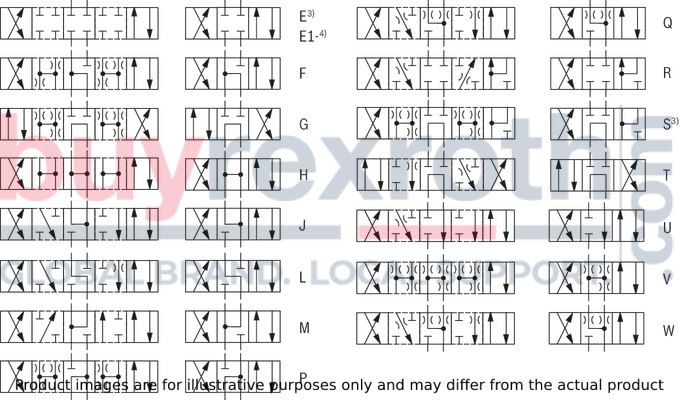
| 3) Example: | |
| – Spool E with actuating side “a” → ordering code ..EA.. | |
| – Spool E with actuating side “b” → ordering code ..EB.. | |
| 4) Spool symbol E1-: P → A/B pre-opening |
Attention!
Caution in conjunction with differential cylinders due to pressure intensification!
|
Order details |
Type of actuation |
||
|
Symbol |
Actuating side |
Spool return |
Hand lever |
|
E, E1-, F, G, H, J, L, M, Q, R, S, T, U, V, W |
.A |
..H../F |

|

|
|||
|
.B |
..H../F |

|
|

|
|||
|
..H../F |

|
||

|
|||
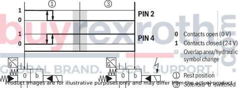
Version QM0
(Position switch on side A, monitored spool position of the main stage "0")
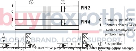
Version QM0
(Position switch on side B, monitored spool position of the main stage "0")
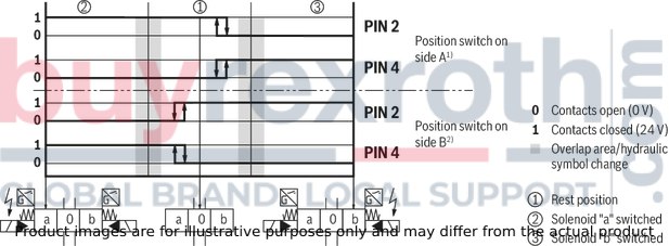
Version QM0
(Position switch on side A and B, monitored spool position "0")
version QMAB
(Position switch on side A and B, monitored spool position "a" and "b")
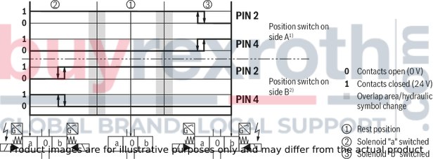
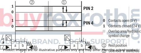
Version QMB
(Position switch on side A, monitored spool position of the main stage "b")

Version QMB
(Position switch on side A, monitored spool position of the main stage "b")
Version QMA
(Position switch on side B, monitored spool position of the main stage "a")
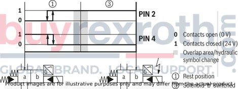
Version QMA
(Position switch on side B, monitored spool position of the main stage "a")
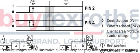
Inductive position switch type QM Switching logics
2 spool positions
3 spool positions
NG10
Dimensions in mm

|
1 |
Main valve |
|
2 |
Pilot control valve: For unit dimensions, see basic data sheets |
|
3 |
Manual override, “N”, optional Actuation of the manual override is only possible up to a tank pressure of approx. 50 bar. Avoid damage to the bore of the manual override! (Special tool for actuation, separate order, material no. R900024943). |
|
5 |
Switching time adjustment (wrench size 6), optional |
|
6 |
Pressure reducing valve, optional |
|
7.1 |
Machined valve contact surface; porting pattern according to ISO 4401-05-05-0-05 |
|
8 |
Seal rings |
|
9 |
Name plate complete valve |
NG16
Dimensions in mm
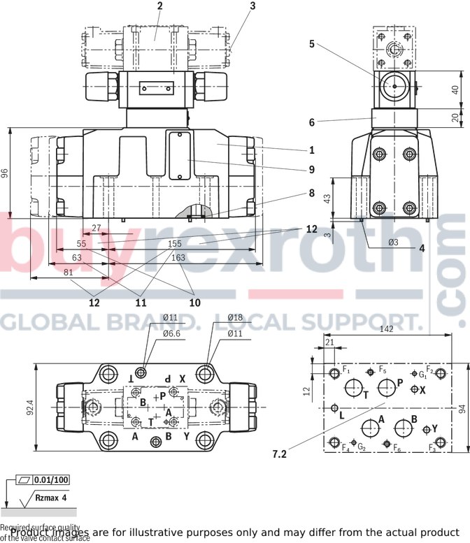
|
1 |
Main valve |
|
2 |
Pilot control valve: For unit dimensions, see basic data sheets |
|
3 |
Manual override, “N”, optional Actuation of the manual override is only possible up to a tank pressure of approx. 50 bar. Avoid damage to the bore of the manual override! (Special tool for actuation, separate order, material no. R900024943). |
|
4 |
Locking pin |
|
5 |
Switching time adjustment (wrench size 6), optional |
|
6 |
Pressure reducing valve, optional |
|
7.2 |
machined valve contact surface; porting pattern according to ISO 4401-07-07-0-05 |
|
8 |
Seal rings |
|
9 |
Name plate complete valve |
|
10 |
2-spool position valves with spring end position in the main valve (spool symbols A, C, D) |
|
11 |
2-spool position valves with spring end position in the main valve (spool symbols B, Y) |
|
12 |
3-spool position valves, spring-centered; |
NG25 (type W.H 22)
Dimensions in mm
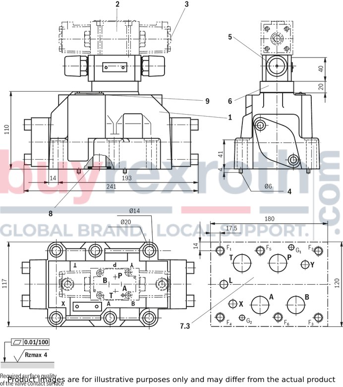
|
1 |
Main valve |
|
2 |
Pilot control valve: For unit dimensions, see basic data sheets |
|
3 |
Manual override, “N”, optional Actuation of the manual override is only possible up to a tank pressure of approx. 50 bar. Avoid damage to the bore of the manual override! (Special tool for actuation, separate order, material no. R900024943). |
|
4 |
Locking pin |
|
5 |
Switching time adjustment (wrench size 6), optional |
|
6 |
Pressure reducing valve, optional |
|
7.3 |
machined valve contact surface; porting pattern according to ISO 4401-08-08-0-05 |
|
8 |
Seal rings |
|
9 |
Name plate complete valve |
NG25 (type W.H 25)
Dimensions in mm
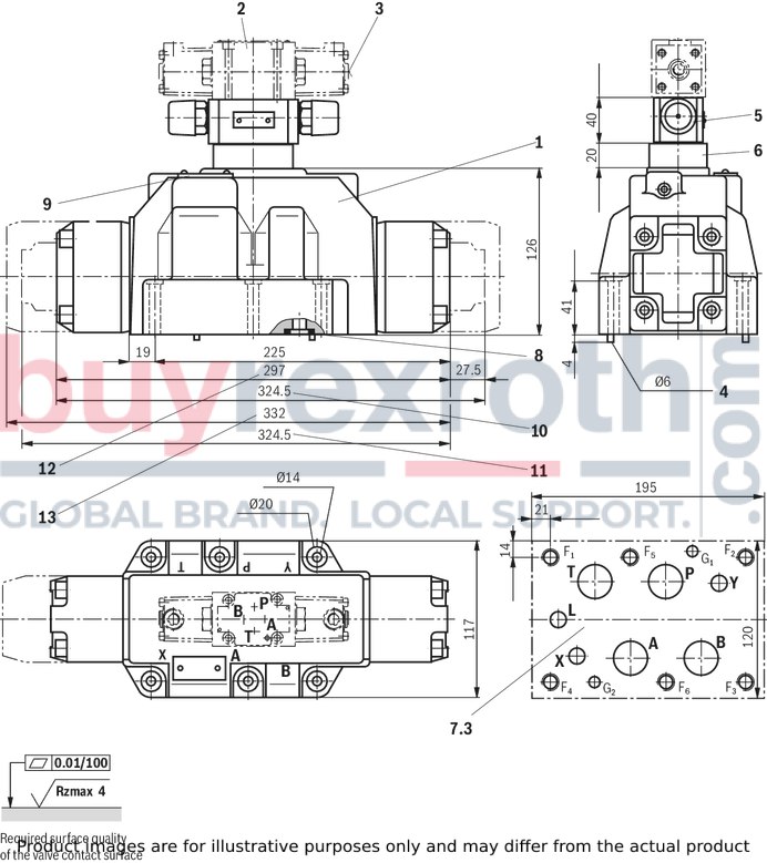
|
1 |
Main valve |
|
2 |
Pilot control valve: For unit dimensions, see basic data sheets |
|
3 |
Manual override, “N”, optional Actuation of the manual override is only possible up to a tank pressure of approx. 50 bar. Avoid damage to the bore of the manual override! (Special tool for actuation, separate order, material no. R900024943). |
|
4 |
Locking pin |
|
5 |
Switching time adjustment (wrench size 6), optional |
|
6 |
Pressure reducing valve, optional |
|
7.3 |
machined valve contact surface; porting pattern according to ISO 4401-08-08-0-05 |
|
8 |
Seal rings |
|
9 |
Name plate complete valve |
|
10 |
2-spool position valves with spring end position in the main valve (spool symbols A, C, D) |
|
11 |
2-spool position valves with spring end position in the main valve (spool symbols B, Y) |
|
12 |
3-spool position valves, spring-centered; |
|
13 |
3-spool position valves, pressure-centered |
Size 32
Dimensions in mm

|
1 |
Main valve |
|
2 |
Pilot control valve: For unit dimensions, see basic data sheets |
|
3 |
Manual override, “N”, optional Actuation of the manual override is only possible up to a tank pressure of approx. 50 bar. Avoid damage to the bore of the manual override! (Special tool for actuation, separate order, material no. R900024943). |
|
4 |
Locking pin |
|
5 |
Switching time adjustment (wrench size 6), optional |
|
6 |
Pressure reducing valve, optional |
|
7.4 |
machined valve contact surface; porting pattern according to ISO 4401-10-09-0-05 |
|
8 |
Seal rings |
|
9 |
Name plate complete valve |
|
10 |
2-spool position valves with spring end position in the main valve (spool symbols A, C, D) |
|
11 |
2-spool position valves with spring end position in the main valve (spool symbols B, Y) |
|
12 |
3-spool position valves, spring-centered; |
|
13 |
3-spool position valves, pressure-centered |
Subplates (separate order)
– NG10 (according to data sheet 45054)
without port X, Y:G 534/01 (G3/4)
G 534/12 (SAE-12; 1 1/16-12)1)
with port X, Y:G 535/01 (G3/4)
G 536/01 (G1)
G 535/12 (SAE-12; 1 1/16-12)1)
G 536/12 (SAE-16; 1 5/16-12)1)
– NG16 (according to data sheet 45056)
G 172/01 (G3/4)
G 172/02 (M27 x 2)
G 174/01 (G1)
G 174/02 (M33 x 2)
G 174/08 (flange)
G 172/12 (SAE-12; 1 1/16-12)1)
G 174/12 (SAE-16; 1 5/16-12)1)
– NG25 (type W.H 22 according to data sheet 45058)
G 151/01 (G1)
G 154/01 (G1 1/4)
G 156/01 (G1 1/2)
G 155/12 (SAE-16; 1 5/16-12)1)
G 154/12 (SAE-20; 1 5/8-20)1)
G 156/12 (SAE-24; 1 7/8-20)1)
– NG25 (type W.H 25 according to data sheet 45058)
G 151/01 (G1)
G 153/01 (G1), for valves with pressure-centered zero position
G 154/01 (G1 1/4)
G 154/08 (flange)
G 156/01 (G1 1/2)
G 153/12 (SAE-16; 1 5/16-12)1)
G 154/12 (SAE-20; 1 5/8-20)1)
G 156/12 (SAE-24; 1 7/8-20)1)
– NG32 (according to data sheet 45060)
G 157/01 (G1 1/2)
G 157/02 (M48 x 2)
G 158/10 (flange)
G 157/12 (SAE-24; 1 7/8-12)1)
1) on request
Valve mounting screws (separate order)
– NG10:
4 metric hexagon socket head cap screws
ISO 4762 - M6 x 45 - 10.9-flZn-240h-L
(friction coefficient μtotal = 0.09 to 0.14);
tightening torque MA = 12.5 Nm ± 10%,
material no. R913000258
4 hexagon socket head cap screws UNC
1/4-20 UNC x 1 3/4″ ASTM-A574
on request
– NG16:
4 metric hexagon socket head cap screws
ISO 4762 - M10 x 60 - 10.9-flZn-240h-L
(friction coefficientμtotal = 0.09 to 0.14);
tightening torqueMA = 75 Nm ± 10%,
material no. R913000116
2 metric hexagon socket head cap screws
ISO 4762 - M6 x 60 - 10.9-flZn-240h-L
(friction coefficientμtotal = 0.09 to 0.14);
tightening torque MA = 12.5 Nm ± 10%,
material no. R913000115
4 hexagon socket head cap screws UNC
3/8-16 UNC x 2 1/4″ ASTM-A574
on request
2 hexagon socket head cap screws UNC
1/4-20 UNC x 1/4″ ASTM-A574
on request
– NG25:
6 metric hexagon socket head cap screws
ISO 4762 - M12 x 60 - 10.9-flZn-240h-L
(friction coefficient μtotal = 0.09 to 0.14);
tightening torqueMA = 130 Nm ± 10%,
material no. R913000121
6 hexagon socket head cap screws UNC
1/2-13 UNC x 2 1/2″ ASTM-A574
on request
– NG32:
6 metric hexagon socket head cap screws
ISO 4762 - M20 x 80 - 10.9-flZn-240h-L
(friction coefficient μtotal = 0.09 to 0.14);
tightening torque MA = 430 Nm ± 10%,
material no. R901035246
6 hexagon socket head cap screws UNC
3/4-10 UNC x 3 1/4″ ASTM-A574
on request
Stroke setting, mounting options

The stroke of the control spool (1) is limited by the stroke setting.
The piston stroke is shortened by loosening the lock nut (2) and clockwise rotation of the adjustment spindle (3). The control chamber (4) must be depressurized for this.
|
NG |
L4 |
|
mm |
|
| 10 | 6.5 |
| 16 | 10 |
| 25 (4W.H22) | 9.5 |
| 25 (4W.H25) | 12.5 |
| 32 | 15 |
5 adjustment range
– NG10:
1 rotation = 1 mm adjustment travel
– NG16 to 32:
1 rotation = 1.5 mm adjustment travel
Stroke setting, mounting options
Stroke limitation on side A

Stroke setting, mounting options
Stroke limitation on side B

|
Mounting options |
NG |
3-spool position valve 1) |
|||||
|
Spring-centered |
Pressure-centered |
||||||
|
L1 (mm) |
L2 (mm) |
L3 (mm) |
L1 (mm) |
L2 (mm) |
L3 (mm) |
||
|
Stroke setting on valve side A and B |
10 |
90 |
144 |
234 |
|
|
|
|
16 |
100 |
200 |
300 |
|
|
|
|
|
25 2) |
96 |
241 |
337 |
|
|
|
|
|
25 3) |
123 |
276 |
399 |
|
|
|
|
|
32 |
133 |
344 |
477 |
|
|
|
|
|
Stroke setting on valve side A |
10 |
90 |
106 |
196 |
|
|
|
|
16 |
100 |
156 |
256 |
|
|
|
|
|
25 2) |
96 |
193 |
289 |
|
|
|
|
|
25 3) |
123 |
225 |
348 |
|
|
|
|
|
32 |
133 |
287 |
420 |
|
|
|
|
|
Stroke setting on valve side B |
10 |
52 |
144 |
196 |
– |
– |
– |
|
16 |
56 |
200 |
256 |
81 |
200 |
281 |
|
|
25 2) |
48 |
241 |
289 |
– |
– |
– |
|
|
25 3) |
72 |
276 |
348 |
107 |
276 |
283 |
|
|
32 |
76 |
344 |
420 |
120 |
344 |
464 |
|
| 1) | With symbol A only version "11", with symbol B only version "12" possible. |
| 2) | Version "W.H 22" |
| 3) | Version "W.H 25" |
| 1) With symbol A only version "11", with symbol B only version "12" possible. | |
| 2) Version "H-WEH 22" | |
| 3) Version "H-WEH 25" |
|
Mounting options |
NG |
2-spool position valve |
||||||||
|
Spring end position |
Hydraulic end position |
|||||||||
|
A, C, D, K, Z |
B, Y |
HC, HD, HK, HZ, HY |
||||||||
|
L1 (mm) |
L2 (mm) |
L3 (mm) |
L1 (mm) |
L2 (mm) |
L3 (mm) |
L1 (mm) |
L2 (mm) |
L3 (mm) |
||
|
Stroke setting on valve side A and B |
10 |
90 |
144 |
234 |
90 |
144 |
234 |
90 |
144 |
234 |
|
16 |
– |
– |
– |
– |
– |
– |
100 |
200 |
300 |
|
|
25 1) |
96 |
241 |
337 |
96 |
241 |
337 |
96 |
241 |
337 |
|
|
25 2) |
– |
– |
– |
– |
– |
– |
123 |
276 |
399 |
|
|
32 |
– |
– |
– |
– |
– |
– |
133 |
344 |
477 |
|
|
Stroke setting on valve side A |
10 |
90 |
106 |
196 |
– |
– |
– |
90 |
106 |
196 |
|
16 |
100 |
180 |
280 |
– |
– |
– |
100 |
156 |
256 |
|
|
25 1) |
96 |
193 |
289 |
96 |
193 |
289 |
96 |
193 |
289 |
|
|
25 2) |
123 |
253 |
376 |
– |
– |
– |
123 |
225 |
348 |
|
|
32 |
133 |
316 |
449 |
– |
– |
– |
133 |
287 |
420 |
|
|
Stroke setting on valve side B |
10 |
52 |
144 |
196 |
52 |
144 |
196 |
52 |
144 |
196 |
|
16 |
– |
– |
– |
80 |
200 |
280 |
56 |
200 |
256 |
|
|
25 1) |
48 |
241 |
289 |
48 |
241 |
289 |
48 |
241 |
289 |
|
|
25 2) |
– |
– |
– |
100 |
276 |
376 |
72 |
276 |
348 |
|
|
32 |
– |
– |
– |
105 |
344 |
449 |
76 |
344 |
420 |
|
| 1) | Version "W.H 22" |
| 2) | Version "W.H 25" |
| 1) Type 4W.H 22 | |
| 2) Type 4W.H 25 |
Spool position monitoring
Dimensions in mm

Inductive position switch type QM
Dimensions in mm

| 1) | Without mating connector |
Notice:
The dimensions are nominal dimensions which are subject to tolerances.
|
Mounting options – 2-spool position valve |
||||||||||||||
|
Monitored spool position |
Ordering code |
NG |
Hydraulic end position HC, HD, HK, HZ |
Spring end position C, D, K, Z |
Spring end position Y |
|||||||||
|
L1 (mm) 1) |
L2 (mm) 1) |
L3 (mm) |
L4 (mm) |
L1 (mm) 1) |
L2 (mm) 1) |
L3 (mm) |
L4 (mm) |
L1 (mm) 1) |
L2 (mm) 1) |
L3 (mm) |
L4 (mm) |
|||
|
„a“ Position switch on side B |
QMAG24 |
10 |
211 |
57 |
211 |
57 |
211 |
57 |
||||||
|
16 |
259 |
55 |
259 |
55 |
||||||||||
|
25 2) |
294 |
47 |
294 |
47 |
294 |
47 |
||||||||
|
25 3) |
325 |
72 |
325 |
72 |
||||||||||
|
32 |
371 |
76 |
371 |
76 |
||||||||||
|
„b“ Position switch on side A |
QMBG24 |
10 |
157 |
111 |
157 |
111 |
157 |
111 |
||||||
|
16 |
159 |
155 |
159 |
155 |
||||||||||
|
25 2) |
149 |
192 |
149 |
192 |
149 |
192 |
||||||||
|
25 3) |
172 |
225 |
172 |
225 |
||||||||||
|
32 |
161 |
287 |
161 |
287 |
||||||||||
|
"a" and "b" Position switch on side A and B |
QMABG24 |
10 |
157 |
211 |
157 |
211 |
157 |
211 |
||||||
|
16 |
159 |
259 |
||||||||||||
|
25 2) |
149 |
294 |
149 |
294 |
149 |
294 |
||||||||
|
25 3) |
172 |
325 |
||||||||||||
|
32 |
161 |
371 |
||||||||||||
| 1) | Without mating connector |
| 2) | Version "W.H 22" |
| 3) | Version "W.H 25" |
| 1) Without mating connector | |
| 2) Type 4W.H 22.. | |
| 3) Type 4W.H 25.. |
|
Mounting options – 3-spool position valve |
||||||||||
|
Monitored spool position |
Ordering code |
NG |
Spring-centered |
Pressure-centered |
||||||
|
L1 (mm) 1) |
L2 (mm) 1) |
L3 (mm) |
L4 (mm) |
L1 (mm) 1) |
L2 (mm) 1) |
L3 (mm) |
L4 (mm) |
|||
|
„a“ Position switch on side B |
QMAG24 |
10 |
211 |
57 |
||||||
|
16 |
259 |
55 |
259 |
81 |
||||||
|
25 2) |
294 |
47 |
||||||||
|
25 3) |
325 |
72 |
325 |
107 |
||||||
|
32 |
371 |
76 |
371 |
120 |
||||||
|
„b“ Position switch on side A |
QMBG24 |
10 |
157 |
111 |
||||||
|
16 |
159 |
155 |
||||||||
|
25 2) |
149 |
192 |
||||||||
|
25 3) |
172 |
225 |
||||||||
|
32 |
161 |
287 |
||||||||
|
"a" and "b" Position switch on side A and B |
QMABG24 |
10 |
157 |
211 |
||||||
|
16 |
159 |
259 |
||||||||
|
25 2) |
149 |
294 |
||||||||
|
25 3) |
172 |
325 |
||||||||
|
32 |
161 |
371 |
||||||||
|
Zero position Position switch on side A and B 2 position switches |
QM0G24 4) |
10 |
157 |
211 |
||||||
|
16 |
159 |
259 |
||||||||
|
25 2) |
149 |
294 |
||||||||
|
25 3) |
172 |
325 |
||||||||
|
32 |
161 |
371 |
||||||||
| 1) | Without mating connector |
| 2) | Version "W.H 22" |
| 3) | Version "W.H 25" |
| 4) | 3-spool position valve |
| 1) Without mating connector | |
| 2) Type 4W.H 22 | |
| 3) Type 4W.H 25 | |
| 4) 3-spool position valve | |
|
Mounting options – 3-spool position valve with one solenoid |
||||||||||||||
|
Monitored spool position |
Ordering code |
NG |
Side A (EA, FA…) Spring-centered |
Solenoids on side B (EB, FB…) Spring-centered |
Side A (EA, FA…) Pressure-centered |
|||||||||
|
L1 (mm) 1) |
L2 (mm) 1) |
L3 (mm) |
L4 (mm) |
L1 (mm) 1) |
L2 (mm) 1) |
L3 (mm) |
L4 (mm) |
L1 (mm) 1) |
L2 (mm) 1) |
L3 (mm) |
L4 (mm) |
|||
|
„a“ Position switch on side B |
QMAG24 |
10 |
211 |
57 |
||||||||||
|
16 |
259 |
55 |
259 |
81 |
||||||||||
|
25 2) |
294 |
47 |
||||||||||||
|
25 3) |
325 |
72 |
325 |
107 |
||||||||||
|
32 |
371 |
371 |
120 |
|||||||||||
|
„b“ Position switch on side A |
QMBG24 |
10 |
157 |
111 |
||||||||||
|
16 |
159 |
155 |
||||||||||||
|
25 2) |
149 |
192 |
||||||||||||
|
25 3) |
172 |
225 |
||||||||||||
|
32 |
161 |
287 |
||||||||||||
|
Zero position Position switch on side A or B 1 position switches |
QM0G24 4) |
10 |
211 |
57 |
157 |
111 |
||||||||
|
16 |
259 |
55 |
159 |
155 |
259 |
81 |
||||||||
|
25 2) |
294 |
47 |
149 |
192 |
||||||||||
|
25 3) |
325 |
72 |
172 |
225 |
325 |
107 |
||||||||
|
32 |
371 |
76 |
161 |
287 |
371 |
120 |
||||||||
| 1) Without mating connector | |
| 2) Type 4W.H 22.. | |
| 3) Type 4W.H 25.. | |
| 4) 2-spool position valve | |
Switching time adjustment
Type 4W.H 10 ..4X/…S, type 4W.H 10 ..4X/…S2

The switching time of the main valve (1) is influenced by using a twin throttle check valve (2) (type Z2FS 6; data sheet 27506).
Modification of supply (3) to discharge control (4):
Remove the pilot control valve (5) – The plate (6) to accept the seal rings stays in place – Turn the switching time adjustment (2) around its longitudinal axis and put it back, install the pilot control valve (5).
Notice:
The modification may only be performed by authorized specialists or at the factory!
"D3” pressure reducing valve
Type 4W.H 10 ..4X/…/..D3
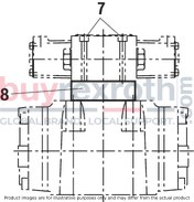
The pressure reducing valve (8) has to be used at a pilot pressure above 250 bar (with type 4W.H 22 …: 210 bar) and with version “H”.
The secondary pressure is kept at a constant level of 45 bar.
Notice:
If a pressure reducing valve "D3" (8) is used, a "B10" throttle insert has to be installed in channel P of the pilot control valve. The modification may only be performed by authorized specialists or at the factory!Preload valve (not for NG10)
In case of valves with depressurized circulation and internal pilot oil supply, the installation of the preload valve (9) in channel P of the main valve is required in order to build up the minimum pilot pressure.
The pressure differential of the preload valve is to be added to the pressure differential of the main valve (see characteristic curves) to result in one total value.
The cracking pressure is approx. 4.5 bar.
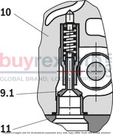

|
9.1 |
Preload valve NG16 |
|
9.2 |
Preload valve NG25 and NG32 |
|
10 |
Main valve |
|
11 |
Subplate |
|
Type |
Material number P4,5 |
|
4W.H 16 … |
R901002365 |
|
4W.H 22 … |
R900315596 |
|
4W.H 25 … |
R900303717 |
|
4W.H 32 … |
R900317066 |
Δp–qVcharacteristic curve (measured with HLP46, ϑOil = 40 °C ± 5 °C)

The secondary pressure is kept at a constant level of 45 bar.
|
1 |
NG16 |
|
2 |
NG25 (type 4W.H 25 …) |
|
3 |
NG25 (type 4W.H 22 …) |
|
4 |
Size 32 |
Related Products
R900962784
$2,379.00 USD
R900965477
$1,456.00 USD
R900433818
$574.00 USD
R978017099
$445.00 USD
R900571712
$1,095.00 USD


