VANE PUMP PVQ2-1X/068RJ15UMB
Manufacturer: Bosch Rexroth
Material #: R900955044
Model : PVQ2-1X/068RJ15UMB
***Disclaimer: The following summary contains information gathered from various sources such as product descriptions, technical specifications and catalogs. While efforts have been made to provide accurate details, inaccuracies may occur. It is advised to verify all information by contacting Bosch Rexroth directly.***
The Bosch Rexroth PVQ2-1X/068RJ15UMB (R900955044) is a high-efficiency displacement pump designed for mobile and industrial applications within an open circuit system. This robust pump features a displacement size of 68 ccm and is capable of withstanding a maximum pressure of 280 bar, making it suitable for demanding operations. It incorporates an axial gap compensation mechanism that enhances its efficiency, particularly in mobile applications.
The PVQ2-1X/068RJ15UMB employs a double-stroke vane pump design that is internally force compensated, which eliminates the need for hydraulic bearing load and contributes to an extended life cycle. It is fitted with NBR seals and has a durable cast iron housing that ensures resilience under challenging conditions. The pump operates with a clockwise rotation direction and has been engineered without through-drive capabilities.
This fixed displacement rotary vane pump is optimized for open loop control systems in mobile applications, offering consistent performance with its constant displacement type. It comes with flange connection working ports for secure installation and maintenance ease. The product's design allows for quick servicing due to the ability to remove the pump insert without detaching the housing from the pump carrier.
In terms of technical specifications, this model operates at a minimum speed of 600 rpm and can achieve a maximum speed of 1800 rpm. The maximum flow rate delivered by this unit is dependent on operating conditions but ensures efficient fluid transfer within the system. The PVQ2-1X/068RJ15UMB does not require an external supply voltage as it functions purely hydraulically.
Overall, the Bosch Rexroth PVQ2-1X/068RJ15UMB offers reliable performance with low wear characteristics, reduced operating noise, and excellent serviceability, making it an ideal choice for both stationary and mobile hydraulic systems requiring consistent fluid power delivery.
$1,540.00 USD
Availability: 1 In Stock
| Qty | Price | Savings |
|---|---|---|
| 5-24 | $1,501.50 USD | $38.50 USD |
| 25+ | $1,463.00 USD | $77.00 USD |
Qty: Delivered as early as December 26, 2025 when ordered in
Qty: Delivered as early as February 13, 2026 when ordered in
This product is eligible for factory repair.
Displacement pump, size 68 ccm, pressure 210 bar for mobile and industrial applications, open circuit
Displacement pump with high efficiency in mobile applications thanks to axial gap compensation. Double-stroke vane pump, internally force compensated without hydraulic bearing load allows for a long life cycle.
Unpacked Weight: 14.201 kg
Fixed displacement Long bearing life through hydraulic relief of the shaft Low wear due to hydraulically unloaded vanes Low operating noise Easy to service due to exchangable pump cartridges Good efficiency Position of the pressure ports can be chosen Drive direction of rotation clockwise or counterclockwise Drive shaft optionally cylinderical or splined Double pump Very compact build Position of the pressure ports can be chosen separately
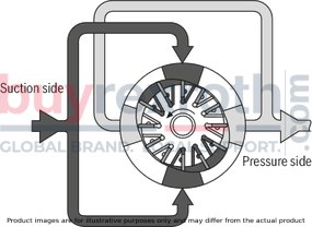
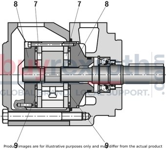
Hydraulic pumps of type PVQ are vane pumps with constant displacement. The rotor (2) running in a stator ring (3) is located on the tooth profile of the drive shaft (1). The slots of the rotor accommodate the vanes (4) which are pressed against the internal surfaces of the stator ring by the centrifugal force upon rotation of the rotor. The displacer chambers are laterally sealed by the control plates (5). Due to the double-eccentric design of the stator ring, there are in each case two pressure chambers opposite of two suction chambers, which provides for hydraulic unloading of the shaft. So it only has to transmit the torque. The vanes are partially unloaded upon passage through the suction range. This unloading has a wear-reducing effect and ensures high efficiency. By simply removing the cover (6), the pump insert (consisting of rotor, vane, stator ring and control plates) can be removed without the need of removing the housing (7) from the pump carrier. This allows for fast maintenance and repair of the pump. Due to the structural design, type PVQ is particularly suitable for mobile applications. The special design of the control plates allows for compensation of the thermal expansion of the rotor and perfect counteraction to sudden pressure changes. Due to the division of the control plates into flexible discs (7) and cover plates (8), counter pressure chambers (9) are formed which are balanced against the pressure in the displacer. This ensures the perfect play between rotor and flexible discs and thus best volumetric efficiencies.
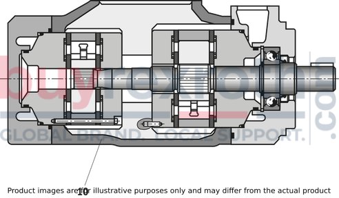
Double pumps are formed by installing two pump installation kits on one joint shaft. The oil inlet is realized by one joint suction port in the central housing (10). The oil outlet is realized separately by both pump installation kits. For the front pump installation kit, the pressure port is located in the flange housing, for the back pump installation kit in the cover. The larger pump installation kit is always located on the flange housing side. Pump installation kits of the same frame size cannot be used as double pumps.
| linear sets with aluminum or cast iron housing |
| Rotary vane fixed displacement pump |
| For mobile applications with open control loop |
| With NBR seals |
| Cast iron housing |
| Size 18 … 193 |
| Maximum operating pressure 210 bar |
| Frame size 1 , 2 , 4 , 5 |
| Fixed displacement |
| Data Sheet | Download Data Sheet |
| 3D CAD | Download 3D CAD |
| 3D CAD | Download 3D CAD |
| 3D CAD | Download 3D CAD |
| Displacement type | constant |
| Size | 68 |
| Max. pressure | 210 |
| Max. flow | 170 |
| Controls | without |
| Supply voltage | 24 VDC |
| Through-drive | without |
| Direction of rotation | clockwise rotation |
| Shaft end | Geared 22-4, 13T 16/32 DP, ISO 3019-1 |
| Fastening | 2-hole mounting flange 101-2 according to ISO 3019-1 |
| Standards | SAE |
| Connection type, working port | Flange connection |
| Hydraulic fluid | HLP,HLPD,HVLP,HVLPD |
| Seals | NBR |
| Speed min. | 600 |
| Productgroup ID | 9,10,11,12,13,14 |
| Speed max. | 2500 |
| Weight | 14.201 |
|
01 |
02 |
03 |
04 |
05 |
06 |
07 |
08 |
09 |
10 |
11 |
12 |
13 |
||
|
PVQ |
– |
1X |
/ |
15 |
* |
|
Pump type |
|||
|
01 |
Mobile version |
PVQ |
|
|
Frame size |
|||
|
02 |
See selection table (e.g. single pump = 2, double pump = 52) |
||
|
Component series |
|||
|
03 |
Component series 10 ... 19 (10 ... 19: unchanged installation and connection dimensions) |
1X |
|
|
Displacement |
|||
|
04 |
See selection table (e.g. 55.2 cm3 = 055) |
||
|
Direction of rotation |
|||
|
05 |
clockwise |
R |
|
|
counterclockwise rotation |
L |
||
|
Shaft end version |
|||
|
06 |
Cylindrical drive shaft (standard) |
A 1) |
|
|
Cylindrical drive shaft (reinforced version) only BG2 to B54 |
B |
||
|
Multi-spline shaft |
J |
||
|
Line connection |
|||
|
07 |
Suction and pressure port: SAE flange connection, mounting thread UNC |
15 |
|
|
Position of the pressure connection at the flange (looking at the cover) |
|||
|
08 |
top (0° from the input) |
D |
|
|
right (90° to the right of the input) |
R |
||
|
counterclockwise (90° to the left of the input) |
L |
||
|
bottom (180° from the input) |
U |
||
|
Position of the pressure connection at the cover (looking at the cover), only with double pumps |
|||
|
09 |
BG21, 41, 42, 51, 52 |
top (45° from the input) |
D |
|
right (135° to the right of the input) |
R |
||
|
counterclockwise (45° to the left of the input) |
L |
||
|
bottom (135° to the left of the input) |
U |
||
|
BG54 |
top (0° from the input) |
D |
|
|
right (90° to the right of the input) |
R |
||
|
counterclockwise (90° to the left of the input) |
L |
||
|
bottom (180° from the input) |
U |
||
|
Seal material |
|||
|
10 |
NBR seals |
M |
|
|
FKM seals |
V |
||
|
Flange design |
|||
|
11 |
BG1, 2, 21 |
101-2 (SAE-B) |
B |
|
BG4, 5, 41, 42, 51, 52, 54 |
127-2 (SAE-C) |
C |
|
|
Through-drive |
|||
|
12 |
Non through-drive |
no code |
|
|
82-2, 16-4 (SAE-A, 9T) |
K01 |
||
|
101-2, 22-4 (SAE-B, 13T) |
K02 |
||
|
127-2, 32-4 (SAE-C, 14T) |
K07 |
||
|
Additional details |
|||
|
13 |
Further details in the plain text |
||
| 1) | Not available for through-drive pumps |
Order example
Single pump: Industrial version (also as mobile version)
PVV 2-1X/055RA15DMB
Double pump: Mobile version (also as industrial version)
PVQ 52-1X/154-068RB15DDMC
Selection table
|
Single pump without through-drive |
|
Single pump with through-drive |
||||
|
Frame size |
Displacement Frame size |
Frame size |
Displacement |
|||
|
1 |
18 cm3 |
= 018 |
2 |
40,1 cm3 |
= 040 |
|
|
27,4 cm3 |
= 027 |
45,4 cm3 |
= 045 |
|||
|
36,4 cm3 |
= 036 |
55,2 cm3 |
= 055 |
|||
|
39,5 cm3 |
= 040 |
60,0 cm3 |
= 060 |
|||
|
45,9 cm3 |
= 046 |
67,5 cm3 |
= 068 |
|||
|
2 |
40,1 cm3 |
= 040 |
4 |
69,0 cm3 |
= 069 |
|
|
45,4 cm3 |
= 045 |
81,6 cm3 |
= 082 |
|||
|
55,2 cm3 |
= 055 |
97,7 cm3 |
= 098 |
|||
|
60,0 cm3 |
= 060 |
112,7 cm3 |
= 113 |
|||
|
67,5 cm3 |
= 068 |
121,6 cm3 |
= 122 |
|||
|
4 |
69,0 cm3 |
= 069 |
5 |
138,6 cm3 |
= 139 |
|
|
81,6 cm3 |
= 082 |
153,5 cm3 |
= 154 |
|||
|
97,7 cm3 |
= 098 |
162,2 cm3 |
= 162 |
|||
|
112,7 cm3 |
= 113 |
183,4 cm3 |
= 183 |
|||
|
121,6 cm3 |
= 122 |
193,4 cm3 |
= 193 |
|||
|
5 |
138,6 cm3 |
= 139 |
||||
|
153,5 cm3 |
= 154 |
|||||
|
162,2 cm3 |
= 162 |
|||||
|
183,4 cm3 |
= 183 |
|||||
|
193,4 cm3 |
= 193 |
|||||
Selection table
|
Double pump |
||||
|
Frame size |
flange-side |
cover-side |
||
|
Displacement |
||||
|
21 |
40,1 cm3 |
= 040 |
18 cm3 |
= 018 |
|
45,4 cm3 |
= 045 |
27,4 cm3 |
= 027 |
|
|
55,2 cm3 |
= 055 |
36,4 cm3 |
= 036 |
|
|
60,0 cm3 |
= 060 |
39,5 cm3 |
= 040 |
|
|
67,5 cm3 |
= 068 |
45,9 cm3 |
= 046 |
|
|
41 |
69,0 cm3 |
= 069 |
18 cm3 |
= 018 |
|
81,6 cm3 |
= 082 |
27,4 cm3 |
= 027 |
|
|
97,7 cm3 |
= 098 |
36,4 cm3 |
= 036 |
|
|
112,7 cm3 |
= 113 |
39,5 cm3 |
= 040 |
|
|
121,6 cm3 |
= 122 |
45,9 cm3 |
= 046 |
|
|
42 |
69,0 cm3 |
= 069 |
40,1 cm3 |
= 040 |
|
81,6 cm3 |
= 082 |
45,4 cm3 |
= 045 |
|
|
97,7 cm3 |
= 098 |
55,2 cm3 |
= 055 |
|
|
112,7 cm3 |
= 113 |
60,0 cm3 |
= 060 |
|
|
121,6 cm3 |
= 122 |
67,5 cm3 |
= 068 |
|
|
51 |
138,6 cm3 |
= 139 |
18 cm3 |
= 018 |
|
153,5 cm3 |
= 154 |
27,4 cm3 |
= 027 |
|
|
162,2 cm3 |
= 162 |
36,4 cm3 |
= 036 |
|
|
183,4 cm3 |
= 183 |
39,5 cm3 |
= 040 |
|
|
193,4 cm3 |
= 193 |
45,9 cm3 |
= 046 |
|
|
52 |
138,6 cm3 |
= 139 |
40,1 cm3 |
= 040 |
|
153,5 cm3 |
= 154 |
45,4 cm3 |
= 045 |
|
|
162,2 cm3 |
= 162 |
55,2 cm3 |
= 055 |
|
|
183,4 cm3 |
= 183 |
60,0 cm3 |
= 060 |
|
|
193,4 cm3 |
= 193 |
67,5 cm3 |
= 068 |
|
|
54 |
138,6 cm3 |
= 139 |
69,0 cm3 |
= 069 |
|
153,5 cm3 |
= 154 |
81,6 cm3 |
= 082 |
|
|
162,2 cm3 |
= 162 |
97,7 cm3 |
= 098 |
|
|
183,4 cm3 |
= 183 |
112,7 cm3 |
= 113 |
|
|
193,4 cm3 |
= 193 |
121,6 cm3 |
= 122 |
|
|
01 |
02 |
03 |
04 |
05 |
06 |
|||
|
INSTALLATION KIT |
PVQ |
– |
1X |
/ |
|
Pump type |
|||
|
01 |
Industrial version |
PVQ |
|
|
Frame size |
|||
|
02 |
Frame Size 1 |
1 |
|
|
Frame Size 2 |
2 |
||
|
Frame size 4 |
4 |
||
|
Frame size 5 |
5 |
||
|
Component series |
|||
|
03 |
Component series 10 ... 19 (10 ... 19: unchanged installation and connection dimensions) |
1X |
|
|
Size / displacement |
|||
|
04 |
Frame Size 1 |
18,0 cm3 |
018 |
|
27,4 cm3 |
027 |
||
|
45,4 cm3 |
036 |
||
|
39,5 cm3 |
040 |
||
|
45,9 cm3 |
046 |
||
|
Frame Size 2 |
40,1 cm3 |
040 |
|
|
45,4 cm3 |
045 |
||
|
55,2 cm3 |
055 |
||
|
60,0 cm3 |
060 |
||
|
67,5 cm3 |
068 |
||
|
Frame size 4 |
69,0 cm3 |
069 |
|
|
81,6 cm3 |
082 |
||
|
97,7 cm3 |
098 |
||
|
112,7 cm3 |
113 |
||
|
121,6 cm3 |
122 |
||
|
Frame size 5 |
138,6 cm3 |
139 |
|
|
153,5 cm3 |
154 |
||
|
162,2 cm3 |
162 |
||
|
183,4 cm3 |
183 |
||
|
193,4 cm3 |
193 |
||
|
Direction of rotation |
|||
|
05 |
clockwise |
R |
|
|
counterclockwise rotation |
L |
||
|
06 |
Installation kit for single pumps or flange-side for double pump |
no code |
|
|
Installation kit for cover-side installation in double pumps |
D |
||
|
Frame size |
|
1 | 2 | 4 | 5 | ||||||||||||||||||
|
Size |
|
18 | 27 | 27 | 27 | 46 | 40 | 45 | 55 | 60 | 68 | 69 | 82 | 98 | 113 | 122 | 139 | 154 | 162 | 183 | 193 | ||
|
Component series |
|
1X | |||||||||||||||||||||
|
Mounting type |
|
Flange mounting according to SAE J744 | |||||||||||||||||||||
|
Line connections |
|
SAE flange design (mounting thread: UNC) | |||||||||||||||||||||
|
Installation position |
|
Any, inlet port at top preferred | |||||||||||||||||||||
|
Shaft load |
|
Radial and axial forces cannot be transmitted | |||||||||||||||||||||
|
Direction of rotation |
|
Drive direction of rotation clockwise or counterclockwise | |||||||||||||||||||||
|
Drive |
|
Direct, coaxial drive | |||||||||||||||||||||
|
Drive speed 1) 2) |
n |
rpm |
600 ... 2,700 | 600 ... 2,500 | 600 ... 2,400 | 600 ... 2,200 | |||||||||||||||||
|
Displacement |
Vg |
cm³ |
18 | 27.4 | 36.4 | 39.5 | 45.9 | 40.1 | 45.4 | 55.2 | 60 | 67.5 | 69 | 81.6 | 97.7 | 112.7 | 121.6 | 138.6 | 153.5 | 162.2 | 183.4 | 193.4 | |
|
Drive power 3) |
Pmax |
kW |
1.1 | 1.5 | 2.2 | 3 | 4 | 5.5 | 7.5 | 11 | |||||||||||||
|
Flow, max. 4) |
qV |
l/min |
26 | 39 | 53 | 59 | 70 | 59 | 66 | 80 | 89 | 100 | 101 | 120 | 141 | 167 | 177 | 203 | 223 | 234 | 267 | 285 | |
|
Operating pressure, absolute |
Inlet 5) |
pmin-max |
bar |
0.83 ... 2.4 6) | 0.83 ... 2.4 | 0.83 ... 2.4 6) | |||||||||||||||||
|
Outlet |
pmax |
bar |
210 | 160 | 140 | 210 | 175 | ||||||||||||||||
|
Pressure peak |
pmax |
|
At most 10 % over the max. permanent output pressure; not longer than 0.5 s | ||||||||||||||||||||
|
Mass 7) |
m |
kg |
12 | 14.8 | 23 | 34 | |||||||||||||||||
| 1) | At 1 bar inlet pressure |
| 2) | If phosphoric acid esters (HFD-R) are used, adm. nmax = 1200 rpm |
| 3) | At Δp ≈ 0 bar, n ≈ 1450 rpm |
| 4) | at n = 1500 rpm, p = 0,7 bar, v = 25 mm2/s |
| 5) | Recommended: 1 ... 1,35 bar |
| 6) | If liquids containing water and phosphoric acid esters are used, at least 0,9 bar |
| 7) | Single pump without through-drive |
Hydraulic fluid
|
Permissible hydraulic fluid 1) |
Mineral oil (HLP) to DIN 51524-2 | |
|
Hydraulic fluid temperature range 2) |
°C |
-10 … +70 |
|
Viscosity range |
mm²/s |
13 … 860 |
|
Maximum admissible degree of contamination of the hydraulic fluid 3) |
Class 20/18/15 according to ISO 4406 (c) |
| 1) | For more information and data on the use of other hydraulic fluids please contact us. |
| 2) | Observe the admissible viscosity range! |
| 3) | The cleanliness classes specified for the components must be adhered to in hydraulic systems. Effective filtration prevents faults and simultaneously increases the life cycle of the components. For the selection of the filters, see www.boschrexroth.com/filter. |
For applications outside these parameters, please consult us!
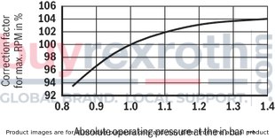
The specified values for the max. drive speed apply to an absolute pressure at the input of 1 bar.
Depending on the absolute pressure at the input, the admissible max. speed must be corrected according to the following diagram.
BG1; BG2; BG4; BG21; BG41; BG42
BG5; BG51; BG52; BG54

Drive torque (measured with ν = 41 mm2/s; ϑ = 50 °C)

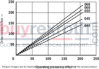
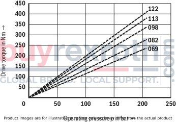

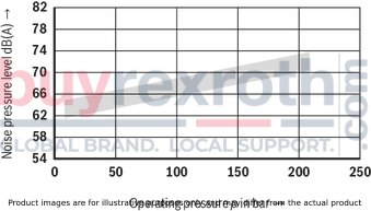
Sound pressure level measured in the low-noise chamber according to DIN 45635 part 26.
Distance microphone - pump = 1 m. ν = 41 mm2/s; n = 1500 and ϑ = 50 °C
BG1

BG2

BG4
BG5

The sound pressure levels for double pumps are - on the average - 1 to 3 db(A) higher than the values for single pumps.
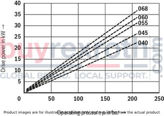
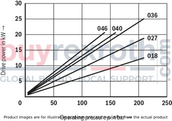
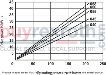
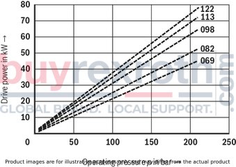
Drive power (measured with ν = 41 mm2/s; ϑ = 50 °C)
n = 1500 min-1
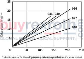


n = 1800 min-1

Displacement, speed-dependent (measured with ν = 41 mm2/s; ϑ = 50 °C; p = 7 bar)

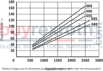
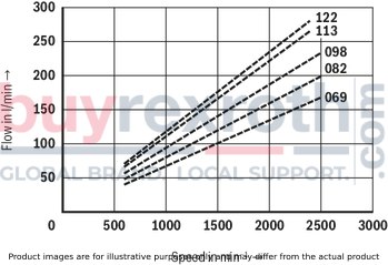
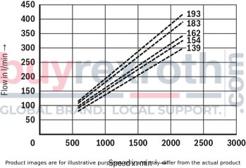
Double pump

Single pump

Single pump PVV / PVQ, BG1
Dimensions in mm
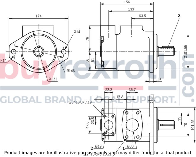
|
1 |
Suction port SAE 1 1/2“ |
|
2 |
Pressure connection SAE 3/4" |
|
3 |
cylindrical drive shaft |
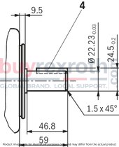
Shaft end for BG1
Version "A"
Cylindrical drive shaft (standard)
4 fitting key ▢ 4.76 x 31.8
Admissible torque 250 Nm
Dimensions in mm
Version J
Multi-spline shaft SAE-B 7/8”
13 teeth 16/32DP
Tooth thickness t = 2.261
Admissible torque 316 Nm
Dimensions in mm

Single pump PVV / PVQ, BG2; 4; 5
Dimensions in mm

|
1 |
Suction port |
|
2 |
Pressure port |
|
3 |
Cylindrical drive shaft (nominal dimensions of the drive shafts see double pump PVV / PVQ, BG54) |
|
BG |
Suction port |
||||||
|
ØD5 |
D8-2B |
B3 |
L6 |
L4 |
H1 |
||
|
2 |
SAE 1 1/2" |
38 mm |
1/2"-13UNC; 22 mm |
69,9 mm |
35,7 mm |
120,6 mm |
76,2 mm |
|
4 |
SAE 2" |
50,8 mm |
1/2"-13UNC; 23,8 mm |
77,7 mm |
42,8 mm |
125,5 mm |
82,6 mm |
|
5 |
SAE 3" |
76,2 mm |
5/8"-13UNC; 28,6 mm |
106,3 mm |
61,9 mm |
153,2 mm |
93,6 mm |
|
BG |
Pressure port |
|||||
|
ØD6 |
D7-2B |
B4 |
L7 |
L3 |
||
|
2 |
SAE 1" |
25,4 mm |
3/8"-16UNC; 19 mm |
52,4 mm |
26,2 mm |
38,1 mm |
|
4 |
SAE 1 1/4" |
31,8 mm |
7/16"-14UNC; 22 mm |
58,7 mm |
30,1 mm |
38,1 mm |
|
5 |
SAE 1 1/2" |
38,1 mm |
1/2"-13UNC; 23,8 mm |
69,9 mm |
35,7 mm |
42,9 mm |
|
BG |
Mounting flange |
B2 |
L1 |
H2 |
|||||||
|
B1 |
ØD1 |
ØD2 |
ØD3 |
ØD4-0,05 mm |
L2 |
L5 |
|||||
|
2 |
SAE-B |
174 mm |
14 mm |
146 mm |
121 mm |
101,6 mm |
9,5 mm |
13 mm |
117 mm |
163 mm |
64 mm |
|
4 |
SAE-C |
212 mm |
17,5 mm |
181 mm |
148 mm |
127 mm |
9,5 mm |
16 mm |
140 mm |
186 mm |
70 mm |
|
5 |
SAE-C |
212 mm |
17,5 mm |
181 mm |
148 mm |
127 mm |
12,7 mm |
16 mm |
159 mm |
216 mm |
83 mm |
PVV / PVQ 2...K.. - with through-drive
Dimensions in mm

PVV / PVQ 4...K.. - with through-drive
Dimensions in mm
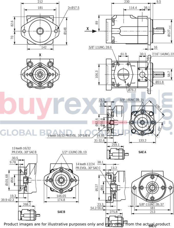
PVV, PVQ 5...K.. - with through-drive
Dimensions in mm
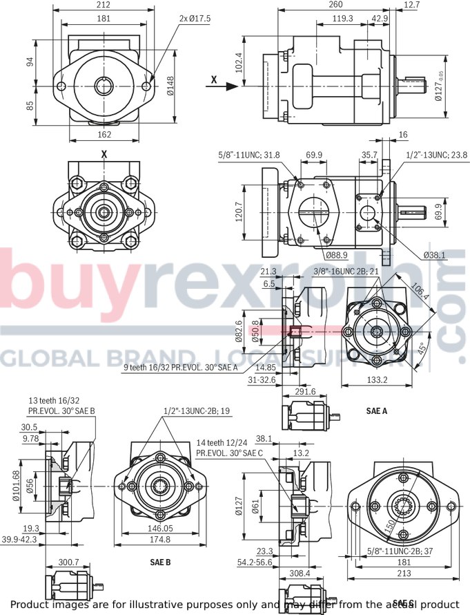
Double pump PVV / PVQ, BG21; 41; 42; 51; 52
Dimensions in mm
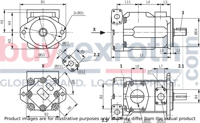
|
1 |
Suction port |
|
2.1 |
Pressure connection, flange-side |
|
2.2 |
Pressure connection, cover-side |
|
3 |
Cylindrical drive shaft (nominal dimensions of the shaft ends see shaft end for BG2 to 54) |
|
BG |
Mounting flange |
|||||||
|
B1 |
ØD1 |
ØD2 |
ØD3 |
ØD4-0,05 mm |
L2 |
L5 |
||
|
21 |
SAE-B |
174 mm |
14 mm |
146 mm |
121 mm |
101,6 mm |
9,5 mm |
13 mm |
|
41; 42 |
SAE-C |
212 mm |
17,5 mm |
181 mm |
148 mm |
127 mm |
9,5 mm |
16 mm |
|
51; 52 |
SAE-C |
212 mm |
17,5 mm |
181 mm |
148 mm |
127 mm |
12,7 mm |
16 mm |
|
BG |
Suction port |
||||||
|
ØD5 |
D8-2B |
B3 |
L6 |
L4 |
H1 |
||
|
21 |
SAE 1 1/2" |
63,5 mm |
1/2"-13UNC; 23,8 mm |
88,5 mm |
50,8 mm |
101,6 mm |
84,1 mm |
|
41; 42 |
SAE 3" |
76,2 mm |
5/8"-11UNC; 28,6 mm |
106,3 mm |
61,9 mm |
114,4 mm |
88,9 mm |
|
51; 52 |
SAE 3 1/2" |
88,9 mm |
5/8"-11UNC; 31,8 mm |
120,7 mm |
69,9 mm |
119,3 mm |
102,4 mm |
|
BG |
Pressure connection, flange-side |
||||||
|
ØD6 |
D7-2B |
B4 |
L7 |
L3 |
H4 |
||
|
21 |
SAE 1" |
25,4 mm |
3/8"- 16UNC; 19,1 mm |
52,4 mm |
26,2 mm |
38,1 mm |
76,2 mm |
|
41; 42 |
SAE 1 1/4" |
31,8 mm |
7/16"- 14UNC; 21,6 mm |
58,7 mm |
30,1 mm |
38,1 mm |
82,6 mm |
|
51; 52 |
SAE 1 1/2" |
38,1 mm |
1/2"- 13UNC; 23,8 mm |
69,9 mm |
35,7 mm |
42,9 mm |
93,6 mm |
|
BG |
Pressure connection, cover-side |
|||||||||
|
ØD11 |
D12-2B |
B5 |
L12 |
L11 |
H6 |
B2 |
L1 |
H2 |
||
|
21 |
SAE 3/4" |
19,1 mm |
3/8"-16UNC; 19,1 mm |
47,6 mm |
22,2 mm |
88 mm |
76,2 mm |
132 mm |
252 mm |
64 mm |
|
41 |
SAE 3/4" |
19,1 mm |
3/8"-16UNC; 19,1 mm |
47,6 mm |
22,2 mm |
99,5 mm |
74,7 mm |
140 mm |
275 mm |
70 mm |
|
42 |
SAE 1" |
25,4 mm |
3/8"-16UNC; 19,1 mm |
52,4 mm |
26,2 mm |
109,5 mm |
76,2 mm |
143 mm |
288 mm |
74 mm |
|
51 |
SAE 3/4" |
19,1 mm |
3/8"-16UNC; 19,1 mm |
47,6 mm |
22,2 mm |
119,5 mm |
74,7 mm |
162 mm |
306 mm |
85 mm |
|
52 |
SAE 1" |
25,4 mm |
3/8"-16UNC; 19,1 mm |
52,4 mm |
26,2 mm |
135,8 mm |
76,2 mm |
162 mm |
324 mm |
85 mm |
Double pump PVV / PVQ, BG54
Dimensions in mm
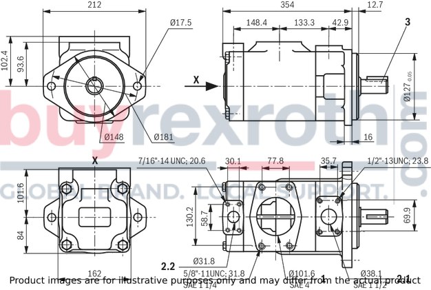
|
1 |
Suction port |
|
2.1 |
Pressure connection, flange-side |
|
2.2 |
Pressure connection, cover-side |
|
3 |
Cylindrical drive shaft (nominal dimensions of the shaft ends see tables) |
|
4 |
Fitting key (dimensions see table) |
Shaft end for BG2 to 54
Dimensions in mm

|
Shaft design A |
||||||
|
BG |
L8 |
L9 |
H3 |
ØD9 |
Fitting key |
Tmax in Nm |
|
2; 21 |
46,8 mm |
59 mm |
24,5-0,2 mm |
22,23-0,3 mm |
▢ 4,76 mm x 31,8 mm |
250 |
|
4; 41; 42 |
61,9 mm |
73,2 mm |
35,2-0,3 mm |
31,75-0,3 mm |
▢ 7,9 mm x 38,1 mm |
407 |
|
5; 51; 52; 54 |
47,8 mm |
62 mm |
35,2-0,3 mm |
31,75-0,3 mm |
▢ 7,9 mm x 28,4 mm |
610 |
|
Shaft design B |
||||||
|
BG |
L8 |
L9 |
H3 |
ØD9 |
Fitting key |
Tmax in Nm |
|
2; 21 |
64 mm |
78 mm |
28,3-0,2 mm |
25,37-0,02 mm |
▢ 6,36 mm x 50,8 mm |
400 |
|
4; 41; 42 |
74,6 mm |
86 mm |
38,6-0,3 mm |
34,9-0,03 mm |
▢ 7,9 mm x 54,6 mm |
600 |
|
5; 51; 52; 54 |
73 mm |
88 mm |
42,37-0,23 mm |
38,07-0,02 mm |
▢ 9,5 mm x 54,6 mm |
810 |
|
Shaft design J |
||||||
|
BG |
L8 |
L9 |
L10 |
ØD10 |
Tmax in Nm |
Gearing data |
|
2; 21 |
33,3 mm |
41 mm |
4 mm |
27,8 mm |
316 |
SAE-B 7/8", 13 teeth, 16/32 DP |
|
4; 41; 42 |
42,1 mm |
56 mm |
3,04 mm |
35,05 mm |
580 |
SAE-C 1/4", 14 teeth, 12/24 DP |
|
5; 51; 52; 54 |
46,6 mm |
56 mm |
9,7 mm |
41,28 mm |
818 |
SAE-C 1/4", 14 teeth, 12/24 DP |
|
Maximum admissible through-drive torques in Nm |
|||
|
BG |
Through-drive |
||
|
K01 (SAE-A, 9T) |
K02 (SAE-B, 13T) |
K07 (SAE-C, 14T) |
|
|
2 |
131 |
316 |
- |
|
4 |
131 |
316 |
437 |
|
5 |
131 |
384 |
702 |
SAE connection flanges
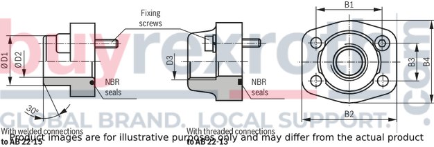
|
Suction port |
Pressure connection for PVV / PVQ 1) |
NG |
Seal material |
Material number for flange with |
B1 |
B2 |
B3 |
B4 |
ØD1 |
ØD2 |
D3 |
Mounting screws |
|
|
Welded connection |
Threaded connection |
||||||||||||
|
1; 21; 41; 51 |
3/4“ |
NBR |
R900211169 |
R900063050 |
47,6 mm |
65 mm |
22,2 mm |
52 mm |
25 mm |
19 mm |
G3/4 |
3/8"-16UNC |
|
|
2; 21; 42; 52 |
1“ |
NBR |
R900211170 |
R900211175 |
52,4 mm |
70 mm |
26,2 mm |
59 mm |
30 mm |
22 mm |
G1 |
3/8"-16UNC |
|
|
4; 41; 42; 54 |
1 1/4" |
NBR |
R900211363 |
R900211172 |
58,7 mm |
79 mm |
30,2 mm |
68 mm |
38 mm |
28 mm |
G1 1/4 |
7/16"-14UNC |
|
|
5; 51; 52; 54 |
1 1/2" |
NBR |
R900211168 |
R900211171 |
69,9 mm |
95 mm |
35,7 mm |
76 mm |
38 mm |
30 mm |
G1 1/2 |
1/2"-13UNC |
|
|
1; 2 |
1 1/2" |
NBR |
R900211165 |
R900211171 |
69,9 mm |
95 mm |
35,7 mm |
76 mm |
48 mm |
39 mm |
G1 1/2 |
1/2"-13UNC |
|
|
4 |
2" |
NBR |
R900211434 |
R900211173 |
77,8 mm |
102 mm |
42,9 mm |
90 mm |
60 mm |
49 mm |
G2 |
1/2"-13UNC |
|
|
21 |
2 1/2" |
NBR |
R900063063 |
R900211174 |
88,9 mm |
114 mm |
50,8 mm |
104 mm |
76 mm |
62 mm |
G2 1/2 |
1/2"-13UNC |
|
|
5; 41; 42 |
3" |
NBR |
R900211362 |
‒ |
106,3 mm |
135 mm |
61,9 mm |
131 mm |
76 mm |
70 mm |
‒ |
5/8"-11UNC |
|
|
51; 52 |
3 1/2" |
NBR |
R900211166 |
‒ |
130,7 mm |
152 mm |
69,9 mm |
140 mm |
89 mm |
82 mm |
‒ |
5/8"-11UNC |
|
|
54 |
4" |
NBR |
R900211167 |
‒ |
130,2 mm |
162 mm |
77,8 mm |
152 mm |
114 mm |
107 mm |
‒ |
5/8"-11UNC |
|
| 1) | Bold figure specifies the stage for which the flange (with double pumps) is intended. |
The material numbers comprise the flange, the O-ring and the mounting screws.
Pipe thread "G" according to ISO 228/1
Comprehensive information and suggestions are contained in the Hydraulics Trainer, volume 3, RE 00281, “Project planning information and design of hydraulic systems".
When using vane pumps, we recommend particularly observing the information specified below.
Technical data
All specified Technical data depend on production tolerances and are valid at certain boundary conditions.
Please note that consequently, fluctuations are possible and that with certain boundary conditions (e.g. viscosity), the Technical data may also change.
Characteristic curves
When designing the drive motor, please observe the maximum application parameters possible shown by the presented characteristic curves.
Noise
The values for sound pressure level shown on page 8 have been measured based on DIN 45635, sheet 26. That means that only the sound emission of the pump is shown.
Environmental influences (place of installation, piping, etc.) have not been considered.
These values are in each case only valid for one pump.
With unfavorable influences at the place of installation of the power unit, the sound pressure level may, however, still be 5 to 10 db(A) higher than the values of the pump itself.
Drive
Electric motor + pump carrier + coupling + pump

Attention!
no radial and axial forces on the pump drive shaft admissible! Motor and pump must be exactly aligned! use a torsionally flexible couplingFluid tank
Adjust useful volume of the tank to the operating conditions.Attention!
The admissible fluid temperature must not be exceeded use coolers, if necessary!Lines and connections
Cut with an inclination of 45° Remove the protective plug at the pump We recommend using seamless precision steel pipes according to DIN 2391 and releasable pipe connections. Select the inner width of the pipes according to the connections Pipelines and fittings must be carefully cleaned before assembly. – min. distance 120 mm to the tank bottom Dirt deposits are not sucked in or raised min. 50 mm immersion depth, also with lowest fluid level admissible Foam formation is avoided Leakage and return fluid must not be directly sucked in again under any circumstances! Liquid temperature remains low For the inlet pressure refer to the Technical dataRecommendation for pipe-laying
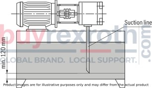 Return fluid must not be directly sucked in again under any circumstances, i.e. select the largest distance possible between suction and return line Return flow outlet must always lie below the oil level Ensure suction-tight assembly of the pipelines
Filter
Use return flow or pressure filter if possible. (Suction filters only in connection with underpressure switch/clogging indicator).Hydraulic fluid
Please observe our provisions according to catalog sheet RE 07075. We recommend brand hydraulic fluids. Different hydraulic fluid types must not be mixed as this might result in degradation and deterioration of the lubricity. According to the operating conditions, the liquid must be renewed at certain time intervals. In this connection, it is also necessary to clean the fluid tank from residues.admissible installation positions
horizontal position preferredB3

B5

V1

Commissioning
Check whether the system has been assembled carefully and properly. Only fill in hydraulic fluid through filters with the required minimum retention rate. Observe the arrow indicating the direction of rotation. Start up the pump without load and allow to pump at zero pressure for some seconds in order to allow for sufficient lubrication. Do not operate the pump without oil under any circumstances. If the pump does not deliver medium without bubbles after approx. 20 seconds, the system must be checked once again. After the operating values have been reached, check the pipe connections for leak-tightness. Check the operating temperature.Bleeding
Before the initial commissioning, we recommend filling the housing and the suction line of the pump with oil. This increases the operational safety and prevents wear in case of unfavorable installation conditions. During the initial commissioning, the foaming oil has to be discharged in circulation at zero pressure by carefully opening the pressure flange (provide splashguard, if necessary). Only re-tighten the fitting applying the specified torque if bubble-free oil exits.General information
The pumps delivered by us have been checked for function and performance. Changes of any kind at the pump are not admissible; otherwise, the warranty will become void! Repair works may only be carried out by the manufacturer or their authorized dealers and agencies. No warranty is accepted for independently performed repairs.Notice!
Assembly, maintenance and repair of the pump may only be carried out by authorized, trained and instructed personnel. Pump may only be operated with the admissible data (see Technical data)! The pump may only be operated if it is in an unobjectionable condition. For all works at the pump, depressurize the system! Unauthorized modifications or changes which affect the safety and function are not admissible! Apply protective devices (e. g. coupling guard) and/or do not remove existing protective devices! Always ensure tight seat of all mounting screws! (Observe the specified tightening torque) The generally valid safety and accident prevention regulations must be imperatively complied with!For limitation of the operating pressure or (and) for the solenoid-actuated unloading of the operating pressure, we recommend our pump safety blocks according to RE 25880 and RE 25890.
Related Products
R987108710
$3,389.00 USD
R901088695
$2,918.00 USD
R978918406
$3,897.00 USD
R978916360
$3,897.00 USD
R900710468
$2,230.00 USD


