***Disclaimer: The following summary contains information gathered from various sources such as product descriptions, technical specifications and catalogs. While efforts have been made to provide accurate details, inaccuracies may occur. It is advised to verify all information by contacting Bosch Rexroth directly.***
The Bosch Rexroth PGF2-2X/016RA20VP2 (R900932275) is a high-quality internal gear pump designed for efficient fluid displacement in hydraulic systems. This model boasts a constant displacement feature, thanks to its leakage gap-compensated design, ensuring a reliable and consistent performance. The pump is composed of durable materials including an aluminum alloy for the housing, bearing covers, end covers, and axial washers; steel for the internal gear, pinion shaft, and stop pin; a coppertin compound with a steel back for the plain bearings; brass alloy for the segment and segment support; and plastic sheet seals.
The PGF2-2X/016RA20VP2 is engineered with an involute tooth system which minimizes flow and pressure pulsation, contributing to its notably quiet operation. Its axial compensation ensures excellent sealing of the pressure chamber by maintaining minimal longitudinal gaps between rotating and fixed parts. The radial compensation mechanism provides near leakage gap-free sealing between critical components.
This model's hydrodynamic and hydrostatic mounting allow it to handle forces effectively with hydrodynamically lubricated radial plain bearings for the pinion shaft and a hydrostatic bearing for the internal gear. These features combine to extend service life through reduced wear and tear on components.
With its high efficiency maintained even at low viscosities due to sealing gap compensation, this pump is suitable across a wide range of viscosity and speed conditions. It also demonstrates superior suction characteristics. The unit can be integrated with various other pumps like PGH internal gear pumps, PV vane pumps, or axial piston pumps if needed.
The Bosch Rexroth PGF series is versatile enough to be used in both industrial applications such as machine tools and mobile applications that require high operating pressure like lifting equipment or spreaders. It supports maximum operating pressures up to several hundred bars and offers multiple frame sizes for different displacement volumes measured in cubic centimeters (cm³). Integrated valve technology can also be incorporated upon request to further enhance system functionality.
$1,358.00 USD
More are expected on August 26, 2026
Status: This product is temporarily out of stock.
Qty: Delivered as early as August 26, 2026 when ordered in
This product is eligible for factory repair.
Fixed displacement Low operating noise Low flow pulsation High efficiency also at low viscosity due to sealing gap compensation Long service life due to plain bearings and sealing gap compensation Suitable for broad viscosity and speed ranges Very good suction characteristic All frame sizes and sizes can be combined with each other Can be combined with internal gear pumps PGH, vane pumps PV7 and axial piston pumps Integrated valve technology in the connection cover possible upon request For drives in the minor and medium performance and pressure range in industrial applications, e.g. machine tools With high operating pressure for fatigue-resistant drives in mobile applications, for example lifting equipment, fans and spreaders
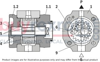
Set-up
Hydraulic pumps of type PGF are leakage gap-compensated internal gear pumps with constant displacement. They basically comprise of housing (1), bearing cover (1.1), end cover (1.2), internal gear (2), pinion shaft (3), plain bearings (4), axial washers (5) and stop pin (6), as well as the segment filler element (7) consisting of segment (7.1), segment support (7.2) and the seal rolls (7.3).
Suction and displacement procedure
The hydrodynamically supported pinion shaft (3) drives the internally geared internal gear (2) in the displayed direction of rotation. During the rotation, there is a volume increase over an angle of approx. 180° in the suction range. An underpressure results and fluid flows into the chambers. The sickle-shaped segment filler element (7) separates suction and pressure chamber. In the pressure chamber, the teeth of the pinion shaft (3) engage in the space between the teeth of the internal gear (2) again. The liquid is displaced via the pressure channel (P).
Axial compensation
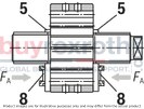
The axial compensation force FA takes effect in the area of the pressure chamber and is generated with the pressure field (8) in the axial washers (5). So the axial longitudinal gaps between the rotating and the fixed parts are extraordinarily small and ensure perfect axial sealing of the pressure chamber.
Radial compensation
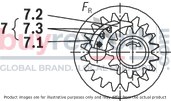
The radial compensation force FR acts on segment (7.1) and segment support (7.2). The area ratios and the position of the sheet seals (7.3) between the segment and segment support are designed so that an almost leakage gap-free sealing between internal gear (2), segment filler element (7) and pinion shaft (3) is achieved. Spring elements under the sheet seal (7.3) ensure sufficient contact pressure, also with very low pressures.
Hydrodynamic and hydrostatic mounting
The forces acting on the pinion shaft (3) are accepted by hydrodynamically lubricated radial plain bearings (4); the forces acting on the internal gear (2) by the hydrostatic bearing (9).
Gear tooth system
The gear tooth system is an involute tooth system. Its large meshing length results in little flow and pressure pulsation; these little pulsation rates considerably contribute to the low-noise running.
Materials used
Housings (1), bearing covers (1.1), end covers (1.2) and axial washers (5): Aluminum alloy internal gear (2), pinion shaft (3) and stop pin (6): steel plain bearing (4): Copper-tin with steel back segment (7.1) and segment support (7.2): brass alloy sheet seals (7.3): Plastic
|
01 |
02 |
03 |
04 |
05 |
06 |
07 |
09 |
10 |
11 |
||
|
PG |
F |
- |
/ |
V |
* |
|
Type |
|||||
|
01 |
Internal gear pump, fixed displacement, gap-compensated |
PG |
|||
|
Series |
|||||
|
02 |
Medium pressure pump, peak pressure 250 bar |
F |
|||
|
Frame size BG |
|||||
|
03 |
BG1 |
1 |
|||
|
BG2 |
2 |
||||
|
BG3 |
3 |
||||
|
Series |
BG1 |
BG2 |
BG3 |
||
|
04 |
Series 20 to 29 (20 to 29: unchanged installation and connection dimensions) |
● |
● |
- |
2X |
|
Series 30 to 39 (30 to 39: unchanged installation and connection dimensions) |
- |
- |
● |
3X |
|
|
Size |
NG |
||||
|
05 |
BG1 |
1.7 |
1,7 |
||
|
2.2 |
2,2 |
||||
|
2.8 |
2,8 |
||||
|
3.2 |
3,2 |
||||
|
4.1 |
4,1 |
||||
|
5.0 |
5,0 |
||||
|
BG2 |
6.3 |
006 |
|||
|
8.0 |
008 |
||||
|
11.0 |
011 |
||||
|
13.0 |
013 |
||||
|
16.0 |
016 |
||||
|
19.0 |
019 |
||||
|
22.0 |
022 |
||||
|
BG3 |
20.0 |
020 |
|||
|
25.0 |
025 |
||||
|
32.0 |
032 |
||||
|
40.0 |
040 |
||||
|
Direction of rotation |
|||||
|
06 |
When looking at the drive shaft |
right |
R |
||
|
counterclockwise |
L |
||||
|
Drive shaft |
|||||
|
07 |
Parallel keyed shaft, ISO 3019-2 |
A |
|||
|
Cylindrical shaft with fitting key, ISO 3019-2 with through-drive |
E |
||||
|
Splined shaft SAE J744 with involute tooth system according to ANSI B92.1a |
J |
||||
|
Dihedral for claw coupling |
N |
||||
|
Dihedral for claw coupling with through-drive |
L |
||||
|
Conical shaft 1:5 with through-drive 1) |
O |
||||
|
Line connections |
|||||
|
08 |
Pipe thread according to ISO 228-1 |
01 |
|||
|
Suction and pressure port according to SAE J518 |
07 |
||||
|
Square flange connection, metric mounting thread |
20 |
||||
|
Seal material |
|||||
|
09 |
FKM (fluor-caoutchouc) |
V |
|||
|
Mounting flange |
|||||
|
10 |
Special flange according to ISO 7653-1985 (for ancillary truck output) |
K4 |
|||
|
4-hole mounting flange according to ISO 3019-2 and VDMA 24560 part 1 |
E4 |
||||
|
2-hole mounting flange according to ISO 3019-1 |
U2 |
||||
|
2-hole mounting flange, centering diameter 32 mm (BG1), centering diameter 52 mm (BG2 and BG3) |
M |
||||
|
2-hole mounting flange, centering diameter 50 mm |
P |
||||
|
2-hole mounting flange, centering diameter 45.24 mm |
P1 |
||||
|
2-hole mounting flange, centering diameter 63 mm |
P2 |
||||
|
Option |
|||||
|
11 |
Anti-cavitation valve |
N |
|||
|
End cover for attachment of the next smaller frame size |
K |
||||
|
12 |
Further details in the plain text |
* |
|||
| 1) | With adapter for truck ancillary drive |
|
Type |
Material number |
|
PGF22X/011RE01VE4 |
R900932271 |
|
Not all variants according to the type key are possible! Please select the desired pump using the selection tables from dimensions to “Conical shaft, with through-drive” or after consultation with Bosch Rexroth! Upon request, special options are possible, for example integrated pressure relief valves. |
|
Multiple pumps
|
01 |
02 |
03 |
04 |
05 |
06 |
07 |
08 |
09 |
10 |
11 |
12 |
13 |
|||||||
|
P3 |
GF2 |
/ |
022 |
+ |
GF2 |
/ |
011 |
+ |
GF1 |
/ |
2.8 |
+ |
+ |
|
Type |
|||
|
01 |
2-fold |
P2 |
|
|
3-fold |
P3 |
||
|
02 |
Series of the 1st pump 1) |
||
|
03 |
Size of the 1st pump 1) |
||
|
04 |
Series of the 2nd pump 1) |
||
|
05 |
Size of the 2nd pump 1) |
||
|
06 |
Series of the 3rd pump 1) |
||
|
07 |
Size of the 3rd pump 1) |
||
|
Direction of rotation |
|||
|
08 |
When looking at the drive shaft |
right |
R |
|
counterclockwise |
L |
||
|
Drive shaft of the 1st pump |
|||
|
09 |
Cylindrical shaft with fitting key, ISO 3019-2 with through-drive |
E |
|
|
Splined shaft SAE J744 with involute tooth system according to ANSI B92.1a |
J |
||
|
Dihedral for claw coupling with through-drive |
L |
||
|
Line connections of the 1st pump |
|||
|
10 |
Pipe thread according to ISO 228-1 |
01 |
|
|
Suction and pressure port according to SAE J518 |
07 |
||
|
Square flange connection, metric mounting thread |
20 |
||
|
Line connections of the 2nd pump |
|||
|
11 |
Pipe thread according to ISO 228-1 |
01 |
|
|
Suction and pressure port according to SAE J518 |
07 |
||
|
Square flange connection, metric mounting thread |
20 |
||
|
Line connections of the 3rd pump |
|||
|
12 |
Pipe thread according to ISO 228-1 |
01 |
|
|
Suction and pressure port according to SAE J518 |
07 |
||
|
Square flange connection, metric mounting thread |
20 |
||
|
Mounting flange of the 1st pump |
|||
|
13 |
Special flange according to ISO 7653-1985 (for ancillary truck output) |
K4 |
|
|
4-hole mounting flange according to ISO 3019-2 and VDMA 24560 part 1 |
E4 |
||
|
2-hole mounting flange according to ISO 3019-1 |
U2 |
||
|
2-hole mounting flange, centering diameter 32 mm (BG1), centering diameter 52 mm (BG2 and BG3) |
M |
||
|
2-hole mounting flange, centering diameter 50 mm |
P |
||
| 1) | Detailed information see type key |
|
Frame size |
1 | 2 | 3 | |||||||||||||||||||
|
Size |
|
1.7 | 2.2 | 2.8 | 3.2 | 4.1 | 5.0 | 6.3 | 8 | 11 | 13 | 16 | 19 | 22 | 20 | 25 | 32 | 40 | ||||
|
Displacement |
geometric |
Vg |
cm³ |
1.7 | 2.2 | 2.8 | 3.2 | 4.1 | 5 | 6.5 | 8.2 | 11 | 13.3 | 16 | 18.9 | 22 | 20.6 | 25.4 | 32.5 | 40.5 | ||
|
Drive speed |
nmin |
rpm |
600 | 500 | ||||||||||||||||||
|
nmax |
rpm |
4500 | 3600 | 4000 | 3600 | 3000 | 3600 | 3200 | 3000 | 2500 | ||||||||||||
|
Operating pressure, absolute |
Inlet |
p |
bar |
0.6 ... 3 | ||||||||||||||||||
|
Outlet |
continuous |
Standard liquid |
pN |
bar |
180 | 210 | 180 | 210 | 180 | 210 | 180 | |||||||||||
|
Outlet |
intermittent 1) |
Standard liquid |
pmax |
bar |
210 | 250 | 210 | 250 | 210 | 250 | 210 | |||||||||||
|
Flow 2) |
qV |
l/min |
2.4 | 3.2 | 4.1 | 4.6 | 6 | 7.2 | 9.4 | 11.9 | 16 | 19.3 | 23.3 | 27.4 | 31.9 | 29.9 | 36.8 | 47.1 | 58.7 | |||
|
Power consumption |
Minimum drive power required 3) |
pzu |
kW |
0.75 | 1.1 | 1.5 | ||||||||||||||||
|
Mass 4) |
m |
kg |
0.8 | 0.9 | 1 | 1.1 | 1.3 | 2.1 | 2.2 | 2.4 | 2.6 | 2.7 | 2.9 | 3.1 | 3.3 | 4.1 | 4.5 | 4.9 | ||||
|
Shaft load |
Radial and axial forces (e.g. belt pulley) only after coordination | |||||||||||||||||||||
|
Mounting type |
Flange mounting | |||||||||||||||||||||
| 1) | Maximum 6s, at most 15% of the duty cycle, maximum 2 x 10⁶ load cycles |
| 2) | at n = 1450 rpm, p = 10 bar, v = 30 mm2/s |
| 3) | at p ≈ 1 bar |
| 4) |
For pumps with 2-hole mounting as flange version - Frame size 2 approx. 0.9 kg heavier - Frame size 3 approx. 1.0 kg heavier |
Hydraulic fluid
|
Hydraulic fluid |
|||
|
Permissible hydraulic fluid 1) |
Mineral oil (HL, HLP) according to DIN 51524-1 and DIN 51524-2 HEES liquids according to DIN ISO 15380 HEPR liquids according to DIN ISO 15380 |
||
|
Operating temperature range |
Standard liquid |
°C |
-20 … -100 |
|
Ambient temperature range |
°C |
-20 … +60 | |
|
Viscosity range |
mm²/s |
10 … 300 | |
|
Admissible start viscosity |
mm²/s |
2000 | |
|
Maximum admissible degree of contamination of the hydraulic fluid 2) |
Class 20/18/15 according to ISO 4406 (c) | ||
|
Admissible radial loads of the pinion shaft |
Upon request | ||
| 1) | Other hydraulic fluids on request |
| 2) | The cleanliness classes specified for the components must be adhered to in hydraulic systems. Effective filtration prevents faults and simultaneously increases the life cycle of the components. For the selection of the filters, see www.boschrexroth.com/filter. |
For applications outside these parameters, please consult us!
Notice
For applications outside these parameters, please consult us. Observe our provisions according to data sheet 90220.For applications outside these parameters, please consult us!
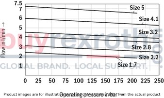
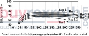
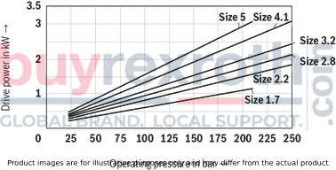
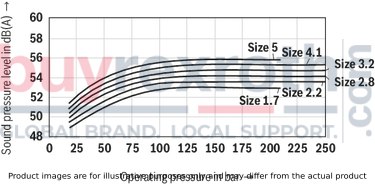
Frame size 1
Flow
Efficiency
Drive power
Sound pressure level
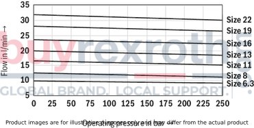
Frame size 2
Flow
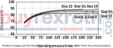
Efficiency
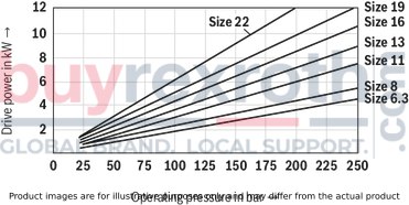
Drive power
Sound pressure level

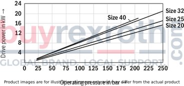
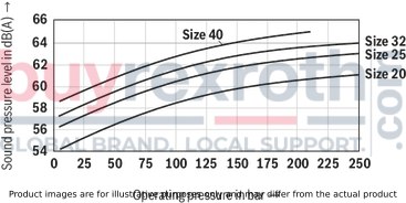
Frame size 3
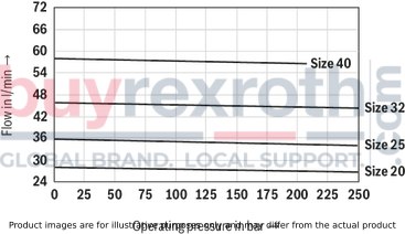
Flow
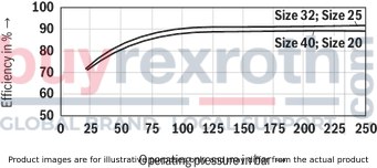
Efficiency
Drive power
Sound pressure level
Notice
Characteristic curves measured with n = 1450 min-1; ν = 40 mm2/s; θ = 40 °C Sound pressure level measured in the sound measuring chamber according to DIN 45635, sheet 26: Distance: Microphone ‒ pump = 1 m
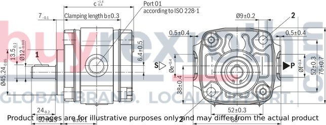
Frame size 1
Cylindrical shaft with fitting key DIN 6885, without through-drive
Dimensions in mm
|
Type |
Material numbers |
a |
b |
c |
Øe |
Øf |
Suction port S according to ISO 228-1 |
Pressure port P according to ISO 228-1 |
||||
|
PGF1-2X/ |
1,7 |
R |
A |
01VP1 |
R9000932132 |
29,6 mm |
49,1 mm |
61,1 mm |
23 mm |
23 mm |
G1/4; 14 mm deep |
G1/4; 12.5 mm deep |
|
2,2 |
R |
A |
01VP1 |
R9000932133 |
29,6 mm |
49,1 mm |
61,1 mm |
23 mm |
23 mm |
G1/4; 14 mm deep |
G1/4; 12.5 mm deep |
|
|
2,8 |
R |
A |
01VP1 |
R9000932134 |
30,7 mm |
51,4 mm |
63,4 mm |
26 mm |
23 mm |
G3/8; 14 mm deep |
G1/4; 12.5 mm deep |
|
|
3,2 |
R |
A |
01VP1 |
R9000932135 |
31,5 mm |
53 mm |
65 mm |
26 mm |
23 mm |
G3/8; 14 mm deep |
G1/4; 12.5 mm deep |
|
|
4,1 |
R |
A |
01VP1 |
R9000932136 |
33,4 mm |
56,7 mm |
68,7 mm |
26 mm |
26 mm |
G3/8; 14 mm deep |
G3/8; 12.5 mm deep |
|
|
5,0 |
R |
A |
01VP1 |
R9000932137 |
35,2 mm |
60,4 mm |
72,4 mm |
27 mm |
26 mm |
G1/2; 14 mm deep |
G3/8; 12.5 mm deep |
|
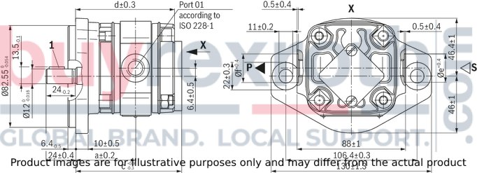
Cylindrical shaft with fitting key DIN 6885, with through-drive
Dimensions in mm
|
Type |
Material numbers |
a |
c |
d |
Øe |
Øf |
Suction port S according to ISO 228-1 |
Pressure port P according to ISO 228-1 |
||||
|
PGF1-2X/ |
1,7 |
R |
E |
01VU2 |
R900086159 |
48,6 mm |
85,7 mm |
79,7 mm |
23 mm |
23 mm |
G1/4; 14 mm deep |
G1/4; 12.5 mm deep |
|
2,2 |
R |
E |
01VU2 |
R900086160 |
48,6 mm |
85,7 mm |
79,7 mm |
23 mm |
23 mm |
G1/4; 14 mm deep |
G1/4; 12.5 mm deep |
|
|
2,8 |
R |
E |
01VU2 |
R900086161 |
49,7 mm |
88 mm |
82 mm |
26 mm |
23 mm |
G3/8; 14 mm deep |
G1/4; 12.5 mm deep |
|
|
3,2 |
R |
E |
01VU2 |
R900086162 |
50,5 mm |
89,6 mm |
83,6 mm |
26 mm |
23 mm |
G3/8; 14 mm deep |
G1/4; 12.5 mm deep |
|
|
4,1 |
R |
E |
01VU2 |
R900086163 |
52,4 mm |
93,3 mm |
87,3 mm |
26 mm |
26 mm |
G3/8; 14 mm deep |
G3/8; 12.5 mm deep |
|
|
5,0 |
R |
E |
01VU2 |
R900086164 |
54,2 mm |
97 mm |
91 mm |
27 mm |
26 mm |
G1/2; 14 mm deep |
G3/8; 14 mm deep |
|
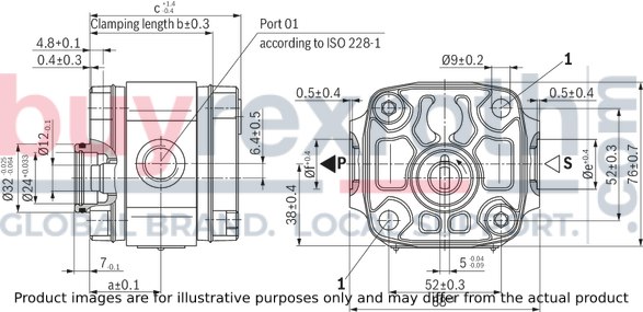
Shaft for claw coupling, without through-drive, back pump
Dimensions in mm
|
Type |
Material numbers |
a |
c |
d |
Øe |
Øf |
Suction port S according to ISO 228-1 |
Pressure port P according to ISO 228-1 |
||||
|
PGF1-2X/ |
1,7 |
L |
N |
01VM |
R900086147 |
29,6 mm |
49,1 mm |
61,1 mm |
23 mm |
23 mm |
G1/4; 14 mm deep |
G1/4; 12.5 mm deep |
|
2,2 |
L |
N |
01VM |
R900086148 |
29,6 mm |
49,1 mm |
61,1 mm |
23 mm |
23 mm |
G1/4; 14 mm deep |
G1/4; 12.5 mm deep |
|
|
3,2 |
L |
N |
01VM |
R900086150 |
31,5 mm |
53 mm |
65 mm |
26 mm |
23 mm |
G3/8; 14 mm deep |
G1/4; 12.5 mm deep |
|
|
4,1 |
L |
N |
01VM |
R900932131 |
33,4 mm |
56,7 mm |
68,7 mm |
26 mm |
26 mm |
G3/8; 14 mm deep |
G3/8; 12.5 mm deep |
|
Driver
Dimensions in mm
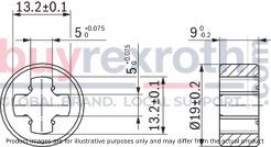
The driver (material number R900984336) is included in the scope of delivery.
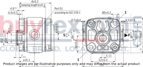
Shaft for claw coupling, with through-drive, central or back pump
Dimensions in mm
|
Type |
Material numbers |
a |
b |
c |
d |
Øe |
Øf |
Suction port S according to ISO 228-1 |
Pressure port P according to ISO 228-1 |
||||
|
PGF1-2X/ |
1,7 |
R |
L |
01VM |
R900086165 |
29,6 mm |
49,1 mm |
66,7 mm |
60,7 mm |
23 mm |
23 mm |
G1/4; 14 mm deep |
G1/4; 12.5 mm deep |
|
L |
R900932093 |
||||||||||||
|
2,2 |
R |
L |
01VM |
R900086166 |
29,6 mm |
49,1 mm |
66,7 mm |
60,7 mm |
23 mm |
23 mm |
G1/4; 14 mm deep |
G1/4; 12.5 mm deep |
|
|
L |
R900932094 |
||||||||||||
|
2,8 |
R |
L |
01VM |
R900932138 |
30,7 mm |
51,4 mm |
69 mm |
63 mm |
26 mm |
23 mm |
G3/8; 14 mm deep |
G1/4; 12.5 mm deep |
|
|
L |
R900951293 |
||||||||||||
|
3,2 |
R |
L |
01VM |
R900086168 |
31,5 mm |
53 mm |
70,6 mm |
64,6 mm |
26 mm |
23 mm |
G3/8; 14 mm deep |
G1/4; 12.5 mm deep |
|
|
L |
R900951294 |
||||||||||||
|
4,1 |
R |
L |
01VM |
R900086169 |
33,4 mm |
56,7 mm |
74,3 mm |
68,3 mm |
26 mm |
26 mm |
G3/8; 14 mm deep |
G3/8; 12.5 mm deep |
|
|
L |
R900088913 |
||||||||||||
|
5,0 |
R |
L |
01VM |
R900086170 |
35,2 mm |
60,4 mm |
78 mm |
72 mm |
27 mm |
26 mm |
G1/2; 14 mm deep |
G3/8; 12.5 mm deep |
|
|
L |
R900951295 |
||||||||||||
Driver
Dimensions in mm

The driver (material number R900984336) is included in the scope of delivery.
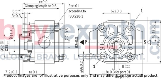
Frame size 2
Shaft for claw coupling, without through-drive, back pump
Dimensions in mm
|
Type |
Material numbers |
a |
b |
c |
Port standard |
Port optional |
||||
|
PGF2-2X/ |
006 |
L |
N |
01VM |
R900563948 |
46 mm |
76 mm |
87,2 mm |
01 |
20 |
|
008 |
L |
N |
01VM |
R900062364 |
47,8 mm |
79,5 mm |
90,7 mm |
01 |
20 |
|
|
011 |
L |
N |
01VM |
R900077364 |
50,5 mm |
85 mm |
96,2 mm |
01 |
20 |
|
|
013 |
L |
N |
20VM |
R900034010 |
53 mm |
90 mm |
101,2 mm |
20 |
01 |
|
|
016 |
L |
N |
20VM |
R900033354 |
55,5 mm |
95 mm |
106,2 mm |
20 |
01 |
|
|
019 |
L |
N |
20VM |
R900932120 |
58,5 mm |
101 mm |
112,2 mm |
20 |
01 |
|
|
022 |
L |
N |
20VM |
R900081192 |
61,5 mm |
107 mm |
118,2 mm |
20 |
- |
|
|
Port 01, pipe thread according to ISO 228-1 |
||
|
NG |
Suction port S |
Pressure port P |
|
006, 008, 011, 013 |
G3/4; 16 deep |
G1/2; 14 mm deep |
|
016, 019 |
G1; 18 mm deep |
G1/2; 14 mm deep |
Driver
Dimensions in mm
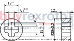
The driver (material number R900981428) is included in the scope of delivery.
Port 20, square flange connection
Suction port S
Dimensions in mm
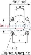
Pressure port P
Dimensions in mm

|
NG |
g |
h |
Pitch circle |
G |
t |
M |
|
006, 008, 011, 013, 016 |
20 mm |
28,3±0.2 mm |
40 mm |
M6 |
10 mm |
10 Nm |
|
019, 022 |
26 mm |
38,9±0,3 mm |
55 mm |
M8 |
12 mm |
25 Nm |
Shaft for claw coupling, without through-drive, back pump
Dimensions in mm
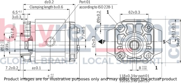
|
Type |
Material numbers |
a |
b |
c |
d |
Port standard |
Port optional |
||||
|
PGF2-2X/ |
006 |
R |
L |
01VM |
R900567307 |
46 mm |
76 mm |
98,2 mm |
87,1 mm |
01 |
20 |
|
L |
R900066012 |
||||||||||
|
008 |
R |
L |
01VM |
R900563291 |
47,8 mm |
79,5 mm |
101,7 mm |
90,6 mm |
01 |
20 |
|
|
L |
R900070239 |
||||||||||
|
011 |
R |
L |
01VM |
R900561146 |
50,5 mm |
85 mm |
107,2 mm |
96,1 mm |
01 |
20 |
|
|
L |
R900073232 |
||||||||||
|
013 |
R |
L |
20VM |
R900049570 |
53 mm |
90 mm |
112,2 mm |
101,1 mm |
20 |
01 |
|
|
L |
R900058674 |
||||||||||
|
016 |
R |
L |
20VM |
R900064718 |
55,5 mm |
95 mm |
117,2 mm |
106,1 mm |
20 |
01 |
|
|
L |
R900983463 |
||||||||||
|
019 |
R |
L |
20VM |
R900932243 |
58,5 mm |
101 mm |
123,2 mm |
112,1 mm |
20 |
01 |
|
|
L |
R900983464 |
||||||||||
|
022 |
R |
L |
20VM |
R900932186 |
61,5 mm |
107 mm |
129,2 mm |
118,1 mm |
20 |
- |
|
|
L |
R900983933 |
||||||||||
|
Port 01, pipe thread according to ISO 228-1 |
||
|
NG |
Suction port S |
Pressure port P |
|
006, 008, 011, 013 |
G3/4; 16 deep |
G1/2; 14 mm deep |
|
016, 019 |
G1; 18 mm deep |
G1/2; 14 mm deep |
Driver
Dimensions in mm

The driver (material number R900981428) is included in the scope of delivery.
Port 20, square flange connection
Suction port S
Dimensions in mm

Pressure port P
Dimensions in mm

|
NG |
g |
h |
Pitch circle |
G |
t |
M |
|
006, 008, 011, 013, 016 |
20 mm |
28,3±0.2 mm |
40 mm |
M6 |
10 mm |
10 Nm |
|
019, 022 |
26 mm |
38,9±0,3 mm |
55 mm |
M8 |
12 mm |
25 Nm |
Shaft for claw coupling, without through-drive, back pump
Dimensions in mm
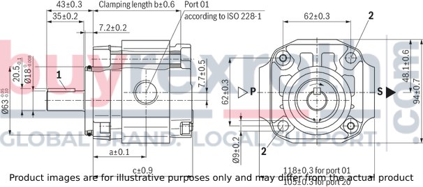
Shaft for claw coupling, without through-drive, back pump
Dimensions in mm
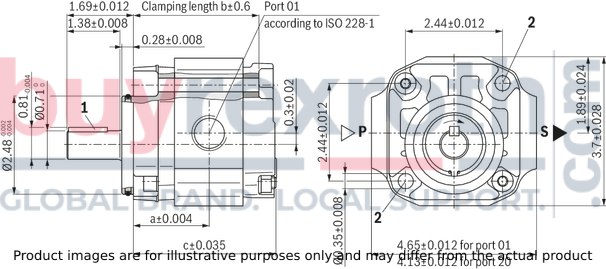
|
Type |
Material numbers |
a |
b |
c |
Port standard |
Port optional |
||||
|
PGF2-2X/ |
006 |
R |
A |
01VP2 |
R900932272 |
46 mm |
76 mm |
87,1 mm |
01 |
20 |
|
008 |
R |
A |
01VP2 |
R900564037 |
47,8 mm |
79,5 mm |
90,7 mm |
01 |
20 |
|
|
011 |
R |
A |
01VP2 |
R900568523 |
50,5 mm |
85 mm |
96,2 mm |
01 |
20 |
|
|
013 |
R |
A |
20VP2 |
R900032712 |
53 mm |
90 mm |
101,2 mm |
20 |
01 |
|
|
016 |
R |
A |
20VP2 |
R900032275 |
55,5 mm |
95 mm |
106,2 mm |
20 |
01 |
|
|
019 |
R |
A |
20VP2 |
R900571401 |
58,5 mm |
101 mm |
112,2 mm |
20 |
01 |
|
|
Port 01, pipe thread according to ISO 228-1 |
||
|
NG |
Suction port S |
Pressure port P |
|
006, 008, 011, 013 |
G3/4; 16 deep |
G1/2; 14 mm deep |
|
016, 019 |
G1; 18 mm deep |
G1/2; 14 mm deep |
Port 20, square flange connection
Suction port S
Dimensions in mm

Pressure port P
Dimensions in mm

|
NG |
g |
h |
Pitch circle |
G |
t |
M |
|
006, 008, 011, 013, 016 |
20 mm |
28,3±0.2 mm |
40 mm |
M6 |
10 mm |
10 Nm |
|
019, 022 |
26 mm |
38,9±0,3 mm |
55 mm |
M8 |
12 mm |
25 Nm |
Cylindrical shaft with fitting key DIN 6885, without through-drive
Dimensions in mm
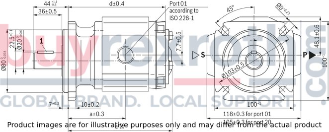
|
Type |
Material numbers |
a |
c |
d |
Port standard |
Port optional |
||||
|
PGF2-2X/ |
006 |
R |
E |
01VE4 |
R900932265 |
63 mm |
115,2 mm |
104,1 mm |
01 |
20 |
|
008 |
R |
E |
01VE4 |
R900932266 |
64,8 mm |
118,7 mm |
107,6 mm |
01 |
20 |
|
|
011 |
R |
E |
01VE4 |
R900932271 |
67,5 mm |
124,2 mm |
113,1 mm |
01 |
20 |
|
|
013 |
R |
E |
20VE4 |
R900943181 |
70 mm |
129,2 mm |
118,1 mm |
20 |
01 |
|
|
016 |
R |
E |
20VE4 |
R900932193 |
72,5 mm |
134,2 mm |
123,1 mm |
20 |
01 |
|
|
019 |
R |
E |
20VE4 |
R900943182 |
75,5 mm |
140,2 mm |
129,1 mm |
20 |
01 |
|
|
022 |
R |
E |
20VE4 |
R900932126 |
78,5 mm |
146,2 mm |
135,1 mm |
20 |
- |
|
|
Port 01, pipe thread according to ISO 228-1 |
||
|
NG |
Suction port S |
Pressure port P |
|
006, 008, 011, 013 |
G3/4; 16 deep |
G1/2; 14 mm deep |
|
016, 019 |
G1; 18 mm deep |
G1/2; 14 mm deep |
Port 20, square flange connection
Suction port S
Dimensions in mm

Pressure port P
Dimensions in mm

|
NG |
g |
h |
Pitch circle |
G |
t |
M |
|
006, 008, 011, 013, 016 |
20 mm |
28,3±0.2 mm |
40 mm |
M6 |
10 mm |
10 Nm |
|
019, 022 |
26 mm |
38,9±0,3 mm |
55 mm |
M8 |
12 mm |
25 Nm |
Splined shaft, with through-drive
Dimensions in mm
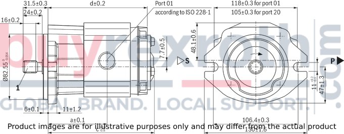
|
Type |
Material numbers |
a |
c |
d |
Port standard |
Port optional |
||||
|
PGF2-2X/ |
006 |
R |
J |
01VU2 |
R900932265 |
65 mm |
117,2 mm |
106,1 mm |
01 |
20 |
|
L |
R900247697 |
|||||||||
|
008 |
R |
J |
01VU2 |
R900932266 |
66,8 mm |
120,7 mm |
109,6 mm |
01 |
20 |
|
|
L |
R900247698 |
|||||||||
|
011 |
R |
J |
01VU2 |
R900932271 |
69,5 mm |
126,2 mm |
115,1 mm |
01 |
20 |
|
|
L |
R900247699 |
|||||||||
|
013 |
R |
J |
20VU2 |
R900943181 |
72 mm |
131,2 mm |
120,1 mm |
20 |
01 |
|
|
L |
R900969259 |
|||||||||
|
016 |
R |
J |
20VU2 |
R900932193 |
74,5 mm |
136,2 mm |
125,1 mm |
20 |
01 |
|
|
L |
R900936173 |
|||||||||
|
019 |
R |
J |
20VU2 |
R900943182 |
77,5 mm |
142,2 mm |
131,1 mm |
20 |
01 |
|
|
L |
R900984300 |
|||||||||
|
022 |
R |
J |
20VU2 |
R900932126 |
80,5 mm |
148,2 mm |
137,1 mm |
20 |
- |
|
|
L |
R900935718 |
|||||||||
|
Port 01, pipe thread according to ISO 228-1 |
||
|
NG |
Suction port S |
Pressure port P |
|
006, 008, 011, 013 |
G3/4; 16 deep |
G1/2; 14 mm deep |
|
016, 019 |
G1; 18 mm deep |
G1/2; 14 mm deep |
Port 20, square flange connection
Suction port S
Dimensions in mm

Pressure port P
Dimensions in mm

|
NG |
g |
h |
Pitch circle |
G |
t |
M |
|
006, 008, 011, 013, 016 |
20 mm |
28,3±0.2 mm |
40 mm |
M6 |
10 mm |
10 Nm |
|
019, 022 |
26 mm |
38,9±0,3 mm |
55 mm |
M8 |
12 mm |
25 Nm |
Frame size 3
Splined shaft, with through-drive
Dimensions in mm
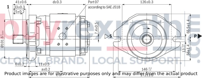
|
Type |
Material numbers |
a |
c |
d |
Port standard |
Port optional |
||||
|
PGF3-3X/ |
020 |
R |
J |
07VU2 |
R900983792 |
79,5 mm |
145,6 mm |
134,5 mm |
07 |
20 |
|
L |
R900948466 |
|||||||||
|
025 |
R |
J |
07VU2 |
R900029617 |
82,5 mm |
151,6 mm |
140,5 mm |
07 |
20 |
|
|
L |
R900950057 |
|||||||||
|
032 |
R |
J |
07VU2 |
R900029561 |
87 mm |
160,6 mm |
149,5 mm |
07 |
20 |
|
|
L |
R900984213 |
|||||||||
|
040 |
R |
J |
07VU2 |
R900931426 |
92 mm |
170,6 mm |
159,5 mm |
07 |
- |
|
|
L |
R900969266 |
|||||||||
Port 07, suction and pressure port according to SAE J518
Suction port S
Dimensions in mm

Pressure port P
Dimensions in mm

|
NG |
k |
Suction port S |
Pressure port P |
|
020, 025 |
16 mm |
1 1/4 in |
3/4 in |
|
032, 040 |
20 mm |
1 1/4 in |
3/4 in |
Port 20, square flange connection
Suction port S
Dimensions in mm

Pressure port P
Dimensions in mm
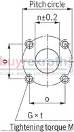
|
NG |
n |
o |
Pitch circle |
G |
t |
M |
|
020, 025 |
12 mm |
24,8±0.2 mm |
35 mm |
M6 |
10 mm |
10 Nm |
|
032 |
20 mm |
38,9±0,3 mm |
55 mm |
M8 |
12 mm |
25 Nm |
Cylindrical shaft with fitting key DIN 6885, without through-drive
Dimensions in mm
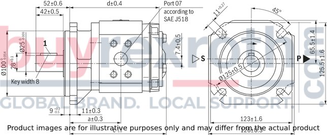
|
Type |
Material numbers |
a |
c |
d |
Port standard |
Port optional |
||||
|
PGF3-3X/ |
020 |
R |
E |
07VE4 |
R900063299 |
71 mm |
137,1 mm |
126 mm |
07 |
20 |
|
025 |
R |
E |
07VE4 |
R900932088 |
74 mm |
143,1 mm |
132 mm |
07 |
20 |
|
|
032 |
R |
E |
07VE4 |
R900932112 |
75,5 mm |
152,1 mm |
141 mm |
07 |
20 |
|
|
040 |
R |
E |
07VE4 |
R900932111 |
83,5 mm |
162,1 mm |
151 mm |
07 |
- |
|
Port 07, suction and pressure port according to SAE J518
Suction port S
Dimensions in mm

Pressure port P
Dimensions in mm

|
NG |
k |
Suction port S |
Pressure port P |
|
020, 025 |
16 mm |
1 1/4 in |
3/4 in |
|
032, 040 |
20 mm |
1 1/4 in |
3/4 in |
Port 20, square flange connection
Suction port S
Dimensions in mm

Pressure port P
Dimensions in mm

|
NG |
n |
o |
Pitch circle |
G |
t |
M |
|
020, 025 |
12 mm |
24,8±0.2 mm |
35 mm |
M6 |
10 mm |
10 Nm |
|
032 |
20 mm |
38,9±0,3 mm |
55 mm |
M8 |
12 mm |
25 Nm |
Shaft for claw coupling, without through-drive, back pump
Dimensions in mm
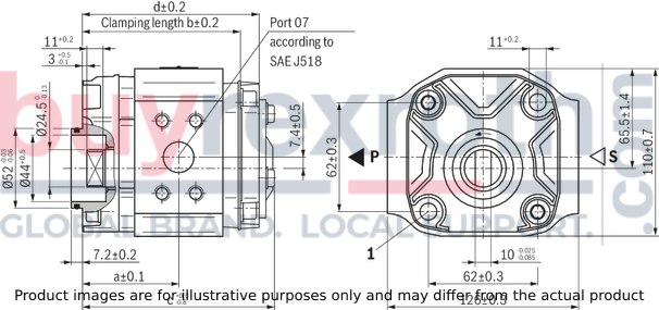
|
Type |
Material numbers |
a |
b |
c |
d |
Port standard |
Port optional |
||||
|
PGF3-3X/ |
020 |
R |
L |
07VM |
R900073539 |
60,5 mm |
99,5 mm |
126,6 mm |
115,5 mm |
07 |
20 |
|
L |
R900758721 |
||||||||||
|
025 |
R |
L |
07VM |
R900932121 |
63,5 mm |
105,5 mm |
132,6 mm |
121,5 mm |
07 |
20 |
|
|
L |
R900960119 |
||||||||||
|
032 |
R |
L |
07VM |
R900074369 |
68 mm |
114,5 mm |
141,6 mm |
130,5 mm |
07 |
20 |
|
|
L |
R900034370 |
||||||||||
|
040 |
R |
L |
07VM |
R900083281 |
73 mm |
124,5 mm |
151,6 mm |
140,5 mm |
07 |
- |
|
|
L |
R900058224 |
||||||||||
Port 07, suction and pressure port according to SAE J518
Suction port S
Dimensions in mm

Pressure port P
Dimensions in mm

|
NG |
k |
Suction port S |
Pressure port P |
|
020, 025 |
16 mm |
1 1/4 in |
3/4 in |
|
032, 040 |
20 mm |
1 1/4 in |
3/4 in |
Port 20, square flange connection
Suction port S
Dimensions in mm

Pressure port P
Dimensions in mm

|
NG |
n |
o |
Pitch circle |
G |
t |
M |
|
020, 025 |
12 mm |
24,8±0.2 mm |
35 mm |
M6 |
10 mm |
10 Nm |
|
032 |
20 mm |
38,9±0,3 mm |
55 mm |
M8 |
12 mm |
25 Nm |
Driver
Dimensions in mm
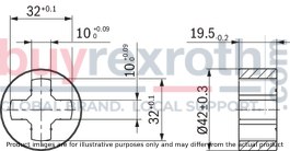
The driver (material number R900983603) is included in the scope of delivery.
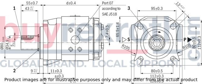
Conical shaft, with through-drive
Dimensions in mm
|
Type |
Material numbers |
a |
c |
d |
Port standard |
Port optional |
||||
|
PGF3-3X/ |
020 |
R |
O |
07VK4 |
R900969302 |
71 mm |
137,1 mm |
126 mm |
07 |
20 |
|
L |
R900619706 |
|||||||||
|
025 |
R |
O |
07VK4 |
R900943169 |
74 mm |
143,1 mm |
132 mm |
07 |
20 |
|
|
L |
R900619710 |
|||||||||
|
032 |
R |
O |
07VK4 |
R900943168 |
78,5 mm |
152,1 mm |
141 mm |
07 |
20 |
|
|
L |
R900943167 |
|||||||||
Port 07, suction and pressure port according to SAE J518
Suction port S
Dimensions in mm

Pressure port P
Dimensions in mm

|
NG |
k |
Suction port S |
Pressure port P |
|
020, 025 |
16 mm |
1 1/4 in |
3/4 in |
|
032, 040 |
20 mm |
1 1/4 in |
3/4 in |
Port 20, square flange connection
Suction port S
Dimensions in mm

Pressure port P
Dimensions in mm

|
NG |
n |
o |
Pitch circle |
G |
t |
M |
|
020, 025 |
12 mm |
24,8±0.2 mm |
35 mm |
M6 |
10 mm |
10 Nm |
|
032 |
20 mm |
38,9±0,3 mm |
55 mm |
M8 |
12 mm |
25 Nm |
Intended use
Internal gear pumps are intended for the set-up of hydraulic drive systems in machine and plant construction.
Technical data
The plant or machine manufacturer must ensure compliance with the admissible technical data and operating conditions. The pump itself does not contain a device to prevent operation outside the admissible data. Operating the pump outside of the admissible technical data is possible to a certain extent, however, this requires the explicit written approval by Bosch Rexroth. All specified technical performance features are average values and apply with the specified boundary conditions. In case of modifications to the basic conditions (e.g. viscosity), the technical data may change as well. Distribution corresponding to the relevant state-of-the-art is possible.
Hydraulic project planning
Bleeding option for commissioning
For Rexroth internal gear pumps PGF.-2/3X, a manual or switchable bleeding option for the initial commissioning or any re-commissioning after maintenance and repair works is to be provided. The bleeding point has to be put into the pressure line in front of the first valve or check valve. Bleeding may only be effected with a maximum counter pressure of 0.2 bar.
Switchable bleeding

Manually operated bleeding

Suction line
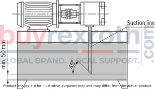
The line cross-sections have to be rated for the designed flows in a manner that an ideal suction speed of 0.6 to 1.2 m/s is achieved on average. The suction speed must not exceed a maximum value of 2 m/s.
The suction cross-sections at the pump itself are designed for the maximum flow and can therefore only be used as reference. In case of continuous operation with speeds lower than the admissible maximum speed, the suction tube diameter is to be dimensioned smaller than the suction port of the pump in accordance with the actual suction speed.
All in all, the suction line is to be designed so that the admissible inlet operating pressure is complied with. Bends and the combination of the suction pipes of several pumps are to be avoided. If a suction filter has to be used, it has to be ensured on the system side that the lowest admissible inlet operating pressure is not exceeded even when the filter is contaminated.
Please ensure air tightness of the transitions and dimensional stability of the suction tube as regards to the external air pressure.
The immersion depth of the suction pipe should be as large as possible (at least 100 mm with lowest liquid level). Dependent on the internal tank pressure, the viscosity of the operating medium and the flow ratios within the tank, no vortex must be formed even during maximum flow. Otherwise, there is the risk that air is sucked in. Return flow and leakage fluid must not be sucked in immediately again.
Dimensions in mm
Pressure line
With pressure lines, sufficient bursting protection of the pipes, hoses and connection elements has to be ensured. The cross-sections should be based on the maximum flow in order to avoid additional excessive load of the pump due to back pressure. Here, you must also consider the pipe losses over the entire pressure line length and other line resistances (e.g. bends, pressure filters).
Pressure limitation
The PGF internal gear pump does not comprise any device for compliance with the maximum operating pressure. Setting and limiting the admissible operating pressure has to be ensured on the system side.
The pressure relief valves necessary for that purpose are to be designed considering the maximum flow and the existing pressure increase speed so that the admissible intermittent operating pressure is not exceeded.
Pressure holding function
In the variable-speed drive, the pump can temporarily also be operated below the specified minimum speed, in the pressure holding function. The holding time and the speed necessary for that purpose results dependent on the operating viscosity and the pressure level. For the design, please contact Bosch Rexroth's technical sales department.
In the deactivated state (speed = 0), a leakage flow flows through the pump back into the tank, dependent on the load pressure. If this is to be prevented, a check valve has to be used.
When using a check valve, please observe the information on bleeding options for the commissioning.
Mechanical project planning
Fastening
The screws must be accessible on the machine side so that the required tightening torque can be applied. The tightening torque of the screws is based on the operating conditions and involved elements of the screw connection and has to be specified by the manufacturer in the power unit, machine or system project planning.
Tank
In the tank construction or the selection of suitable standard tanks, the following requirements are to be observed:
Selection of the largest tank volume possible, dependent on the continuous or average flow, in order to allow for the separation of air bubbles by means of sufficient duration time of the medium in the tank. The air release capacity of the hydraulic fluid used is also of importance. Provision of settling zones for the hydraulic fluid in the tank in order to allow for air release. Provision of guiding plates in order to allowing for the deposit of contamination at the tank bottom outside the pump suction area. Large dimensioning of the tank surfaces dependent on the heat output to be dissipated via the tank walls.Required power unit functions
Hydraulic power units should at least be equipped with the following features:
Tanks, the internal pressure of which corresponds to the ambient pressure in accordance with the design, have to be equipped with breathing filters for pressure compensation purposes. The hydraulic fluid should only be filled in using filling connections excluding filling with unfiltered fluid. The ingress of contamination or humidity must be avoided. In case of use in highly contaminated environments, the tank must to this end be pre-tensioned by means of air pressure. If cleansing of the external tank side is intended or to be expected during the period of use, tank fittings for pipes, lines, or hoses have to be selected, which ensure safe sealing against external pressurization with water jet.Place of installation and environmental conditions
With places of installation from a geodetic height of more than 1000 m, the pump is to be arranged in or below the tank or the tank is to be pre-tensioned by means of compressed air in order to comply with the admissible minimum inlet pressure. A short suction line with large cross-section has to be selected, bends should not be used.
When installing the pump more than 10 m below the tank, the reduction of the inlet pressure to the maximum admissible value has to be ensured by means of additional measures.
When operating the pump in salt-containing or corrosive environments or when pressure loading with strongly abrasive substances is possible, it has to be ensured on the system side that the shaft seal ring and the sealing area of the shaft do not make direct contact with the environment.
Drive
Electric motor + pump carrier + coupling + pump
No radial and axial forces on the pump drive shaft admissible! Motor and pump must be exactly aligned! Always use a coupling that is suitable for compensating shaft displacements!
B3

B5

V1

Pump combinations
With pump combinations it has to be ensured that on every stage, the admissible operating data for the relevant pump type are complied with. The combined pumps must all have the same direction of rotation. The pump with the highest torque, variable displacement pumps or pumps with intermittent load should be provided as first stage in the pump combination. The maximum through-drive torque must be checked by the project planner for every application. This is also true for already existing (coded) pump combinations. The total of the torques in a pump combination must not exceed the maximum drive torque.|
Maximum drive torques [Nm] |
||||||
|
Shaft |
N |
L |
A |
E |
J |
O |
|
PGF1 |
14 |
14 |
30 |
30 |
- |
- |
|
PGF2 |
70 |
70 |
95 |
140 |
90 |
- |
|
PGF3 |
140 |
140 |
- |
230 |
230 |
260 |
|
Formula for drive torque |
|

|
[Nm] |
|
Legende |
|
|
T |
Drive torque [Nm] |
|
Δp |
Operating pressure [bar] |
|
V |
Displacement [cm³] |
|
η |
Hydraulic-mechanical efficiency |
|
Maximum through-drive torques [Nm] |
|||
|
Shaft |
L |
E |
J |
|
PGF1 |
14 |
14 |
- |
|
PGF2 |
70 |
70 |
70 |
|
PGF3 |
140 |
140 |
140 |
Selection
The shaft design of the front pump must be E, J or L. The shaft design of the medium pump must be L. The shaft design of the back pump must be N. If a pump of the next smaller frame size is to be attached, the first pump must have the designation K at the end (e.g. PGF3 + PGF2 ⇒ front pump: PGF3-3X/032RJ07VU2K)Dimensions
The dimensions of the connections correspond to those of single pumps (see Dimensions). The overall length of the pump combination results from the addition of the dimensions “d” of the single pumps (see Dimensions) With the combination of PGF2 and PGF1, the length of the assembly of PGF2 (dimension d) increases by 4.5 mm. With the combination of PGF3 and PGF2, the length of the assembly of PGF3 (dimension d) increases by 2 mm. With the combination of PGF3 and PGF1, the length of the assembly of PGF3 (dimension d) increases by 12.5 mm.
Maintenance schedule and operational safety
For safe operation and a long life cycle of the pump, a maintenance schedule has to be developed for the power unit, the machine, or the system. The maintenance schedule must ensure that the intended or admissible operating conditions of the pump are complied with over the entire period of use.
In particular, compliance with the following operating parameters has to be ensured:
The required oil cleanliness The operating temperature range The filling level of the operating mediumFurthermore, the pump and the system have to be checked for modifications of the following parameters on a regular basis:
Vibrations Noise Temperature difference pump – fluid in the tank Foam formation in the tank Leak-tightnessModifications of these parameters indicate wear of components (e.g. drive motor, coupling, pump, etc.). The cause must be identified and remedied immediately.
In order to achieve high operational safety of the pump in the machine or system, we recommend checking the parameters mentioned above continuously and automatically and shutting the system off automatically in case of modifications exceeding the usual fluctuations in the intended operating range.
Plastic components of drive couplings should be replaced regularly, however, after 5 years at the latest. The relevant manufacturer's specifications must be considered and be given priority.
For preventive maintenance of the pump, we recommend having the seals replaced after a maximum operating time of 5 years by an authorized Bosch Rexroth service company.
Accessories
Pump safety block
For limiting the operating pressure and for the pump circulation at zero pressure, we recommend our pump safety blocks type DBA… according to data sheet 25890.
Automatic bleeding during commissioning is, however, not possible via DBA blocks. In this connection, we recommend separate, manual bleeding.
Related Products
R987109512
$3,029.00 USD
R900961553
$3,097.00 USD
R900935718
$1,465.00 USD
R900219113
$1,211.00 USD
R900519094
$8,883.00 USD


