


PRESSURE GAUGE ABZMM 63- 250BAR/MPA-U/V-G
Manufacturer: Bosch Rexroth
Material #: R900771208
Model : ABZMM 63- 250BAR/MPA-U/V-G
***Disclaimer: The following summary contains information gathered from various sources such as product descriptions, technical specifications and catalogs. While efforts have been made to provide accurate details, inaccuracies may occur. It is advised to verify all information by contacting Bosch Rexroth directly.***
The Bosch Rexroth ABZMM 63-250BAR/MPA-U/V-G (R900771208) is a high-quality pressure gauge designed for measuring and displaying pressure within hydraulic systems. This instrument features a robust stainless steel housing and is filled with fluid to provide effective damping, ensuring accurate readings even in the presence of vibrations or pulsations. The pressure gauge is capable of displaying pressures in both bar and MPa units, with a maximum pressure capacity as indicated by its model code.
Constructed to comply with the EN standard, the ABZMM 63-250BAR/MPA-U/V-G demonstrates Bosch Rexroth's commitment to reliability and precision in manufacturing. It showcases a bicolored scale for clear visibility, and users can benefit from its versatile mounting options, which include screws or brackets. The measuring connection can be positioned at the back or bottom based on installation requirements.
This device is compatible with various types of hydraulic fluids such as HLP, HFC, HFDR, HFDU, HETG, HEES, and HEPG, making it suitable for a diverse range of applications within hydraulic systems. The type of connection utilized is with fitting at the bottom of the gauge for secure attachment. The design ensures that maintenance professionals and system operators can reliably monitor system pressures to maintain optimal performance and safety standards.
$100.00 USD
Availability: 3 In Stock
Ships from US
Qty:
Delivered as early as June 4, 2026
$105.00 USD
Availability: Backordered
Ships from CA
Qty:
Delivered as early as November 20, 2026
DN40Connection on the back side 
|
DN63Port on bottom 
|
DN100Port on bottom 
|
||
DN63Connection on the back side 
|
DN100Connection on the back side 
|
Resistance
|
Hydraulic fluids |
Resistant |
|||
|
Mineral oils |
Mineral oil |
HLP |
according to DIN 51524 |
|
|
Flame-resistant hydraulic fluids |
Water solutions |
HFC |
according to VDMA 24317 |
|
|
Phosphoric acid esters |
HFD-R |
|||
|
Organic esters |
HFD-U |
|||
|
Fast bio-degradable hydraulic fluids |
Triglycerides (rape seed oil) |
HETG |
according to VDMA 24568 |
|
|
Synthetic esters |
HEES |
|||
|
Polyglycols |
HEPG |
|||
|
Water |
Water |
|||
|
Gases |
||||
|
Nitrogen (others gases upon request) |
||||
For applications outside these parameters, please consult us!
Symbol

Dimensions: Pressure gauge DN40, with dual scale – connection centrally at the rear
Dimensions in mm
|
1 |
Bleed or pressure unloading opening |
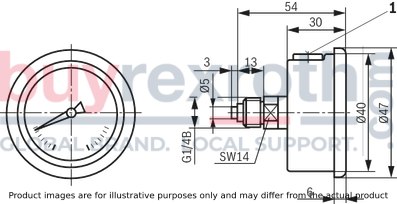
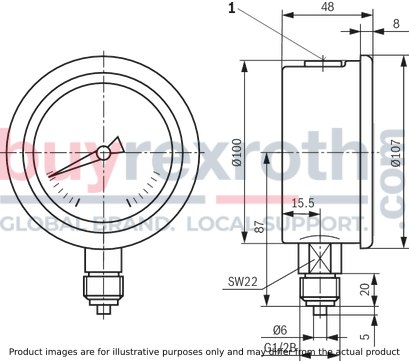
Dimensions: Pressure gauge DN63, with dual scale – connection at the bottom
Dimensions in mm

|
1 |
Bleed or pressure unloading opening |
Dimensions: Pressure gauge DN63, with dual scale – connection centrally at the rear, with mounting clamp
Dimensions in mm
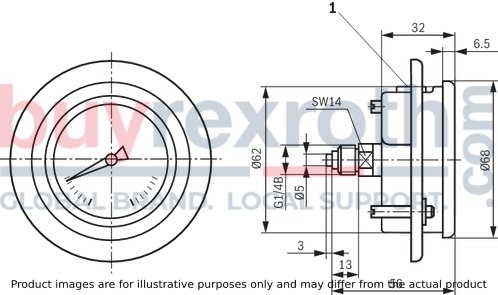
|
1 |
Bleed or pressure unloading opening |
Break-through Ø63+1 mm
Mounting bracket is included in the scope of delivery of the pressure gauge.
Design according to the manufacturer’s choice.
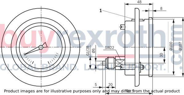
Dimensions: Pressure gauge DN100, with dual scale – connection at the bottom
Dimensions in mm
|
1 |
Bleed or pressure unloading opening |
Dimensions: Pressure gauge DN100, with dual scale – connection eccentrically at the rear, with mounting clamp
Dimensions in mm
|
1 |
Bleed or pressure unloading opening |
Break-through Ø101+1 mm
Mounting bracket is included in the scope of delivery of the pressure gauge.
Design according to the manufacturer’s choice.
Dimensions: Adapter for direct installation of the pressure gauge
Version "A"
Reducing piece for mounting cavity to ISO 1179
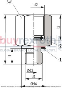
Version "B"
Reducing piece for mounting cavity to ISO 11926-1

|
Version |
PN |
d1 |
d2 |
Ød3 |
Ød4 |
l |
l1 |
l2 |
SW |
Denomination |
Part number |
|
mm |
mm |
mm |
mm |
mm |
|||||||
| A | 630 | G1/4A | G1/4 | 4 | 19 | 34 | 12 | 14.5 | 22 | REDUZIERSTUECK G1/4-G1/4 /FKM | R901156422 |
| 400 | G1/4A | G1/2 | 4 | 19 | 35 | 12 | 16 | 27 | REDUZIERSTUECK G1/4-G1/2 /FKM | R901156423 | |
| B | 630 | 7/16-20UNF | G1/4 | 4 | 16 | 31 | 9 | 14.5 | 22 | REDUZIERSTUECK 7/16-20UNF-G1/4 /FKM | R901156316 |
| 400 | 7/16-20UNF | G1/2 | 4 | 16 | 32 | 9 | 16 | 27 | REDUZIERSTUECK 7/16-20UNF-G1/2 /FKM | R901156317 |
Order example
Reducing piece made of steel, galvanised and yellow-chromated as surface protection G1/4A, female thread = G1/2 with seal ring item 1, material FKM and seal ring item 2, material Cu
REDUZIERSTUECK G1/4-G1/2 /FKM, Material no. R901156423
Spare part: seal ring item 1
|
Version |
Material |
Denomination |
Part number |
| A | FKM | PROFILDICHTUNG M14X1,5+G1/4 FKM | R900012502 |
| B | FKM | O-Ring 8,92x1,83-FKM80+-5SH | R900024577 |
Spare part: Seal ring item 2
|
For thread d2 |
Material |
Ød5 |
Ød6 |
s |
Denomination DICHTRING.... |
Part number |
|
mm |
mm |
mm |
||||
| G1/4 | Cu | 5.9 | 9.3 | 3.2 | 5,9/9,3X3,2-CU NR:9090800 | R900004667 |
| G1/2 | Cu | 8 | 14.8 | 4.2 | 8,0/14,8X4,2-CU NR:9090819 | R900218724 |

Seal ring for metal sealing. After sealing has been achieved, the pressure gauge can still be turned by 360°, so that any desired position can be set.
Marking on the dial
On dual scales, the lettering of the outer scale division (bar) is black, that of the inner scale division red.
Note: Single or dual scales for other pressure ranges (psi, kPa, MPa) on request.

|
1 |
Part number |
|
2 |
Accuracy class according to DIN EN 837 |
|
3 |
"REXROTH" logo |
Normative cross-reference
DIN EN 837-1
Pressure gauges - part 1: Bourdon tube pressure gauges; dimensions, metrology, requirements and testing
DIN EN 837-2
Pressure gauges - part 2: Selection and installation recommendations for pressure gauges
DIN 51524
Pressure fluids; hydraulic oils
VDMA 24317
Fluid power - flame-retardant hydraulic fluids – technical minimum requirements
VDMA 24568
Fluid power; fast bio-degradable hydraulic fluids; technical minimum requirements;
Related Products
R900771208
$100.00 USD

R900027254
$85.00 USD

R900022458
$76.00 USD

R901257616
$256.00 USD

R900027265
$202.00 USD


