***Disclaimer: The following summary contains information gathered from various sources such as product descriptions, technical specifications and catalogs. While efforts have been made to provide accurate details, inaccuracies may occur. It is advised to verify all information by contacting Bosch Rexroth directly.***
The Bosch Rexroth SF 200 A1-1-4X//12 (R900565008) is a high-quality pilot operated check valve designed for tank installation and characterized by its robust flange connection. This particular model comes from a series that offers versatility through its cartridge valve design without control open spool, ensuring reliable operation in various hydraulic applications. The SF 200 A1-1-4X//12 is engineered to reduce switching noises, which is achieved by incorporating damping measures into the design.
This model features a housing with a low-pressure flange that can be continuously rotated for ease of installation and alignment within hydraulic systems. It includes a control cylinder and has provisions for mounting screws and ports X and Y, with the connection flange available upon request. The valve's nameplate provides clear identification, ensuring proper maintenance and serviceability.
The SF 200 A1-1-4X//12 is designed without a position switch but can be ordered in version QGZ if an inductive position switch is required. The number of flange mounting screws (N) is evenly arranged at the circumference for secure attachment, which aligns with the type of connection A specified for this model.
This Bosch Rexroth check valve operates efficiently under significant pressure conditions, although specific maximum operating pressures and flow rates are defined by the component series to which this particular model belongs. Users can expect higher operating pressures upon request to cater to more demanding applications.
Overall, the Bosch Rexroth SF 200 A1-1-4X//12 check valve stands out due to its adaptability, ease of integration into existing systems, noise reduction capabilities during operation, and potential customization options to meet specific requirements in fluid power operations.
$26,544.00 USD
More are expected on June 16, 2025
Status: This product is temporarily out of stock.
Qty: Delivered as early as June 16, 2025 when ordered in
This product is eligible for factory repair.
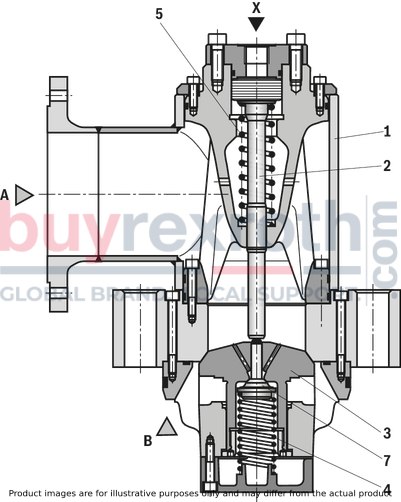
Pilot operated check valve, with or without pre-decompression Flange connection Tank installation Cartridge valve without control open spool (check valve) Reduced switching noises due to damping measures Rotatable low-pressure connection (housing) Inductive position switch, optional Higher operating pressures, on request
Type SF . .1-1-4X/…
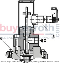
Type SF . A0-1-4X/Q2G24Z
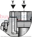
Type SF . .0-1-4X/…
Type SF . .0-1-4X/…
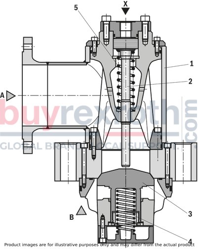
Type SF 500 .1-1-4X/…
1 |
Housing with low-pressure flange, continuously rotatable |
2 |
Name plate |
3 |
Control cylinder |
4 |
Connection G1 1/2 (draining); tightening torque MA = 300 Nm ±10 % |
5 |
Ring |
6 |
Mounting screws |
7 |
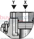
Port Y; connection flange on request |
8 |
Port X; connection flange on request |
9 N1 |
Number of the flange mounting screws evenly arranged at the circumference (type of connection "A") |
10 N2 |
Number of the valve mounting screws evenly arranged at the circumference |
11 |
Version "without position switch" |
12 |
Version "Q2G24Z" |
01 |
Prefill valve |
SF |
02 |
Size 125 |
125 |
Size 150 |
150 |
|
Size 200 |
200 |
|
Size 250 |
250 |
|
Size 300 |
300 |
|
Size 350 |
350 |
|
Size 400 |
400 |
|
Size 500 (only version "A" and "B") |
500 |
|
03 |
Flange connection |
A |
Tank installation |
B |
|
Screw-in cartridge valve without control spool (check valve) |
K |
|
04 |
without pre-decompression |
0 |
With pre-decompression |
1 |
|
Spring feedback of the main poppet |
||
05 |
Cracking pressure ≈ 0.2 bar |
1 |
06 |
Component series 40 to 49 (40 to 49: unchanged installation and connection dimensions) |
4X |
Spool position monitoring |
||
07 |
Without position switch |
no code |
With inductive position switch, position monitoring "open", with connector plug (only version "A0") |
Q2G24Z |
|
Seal material |
||
08 |
NBR seals |
no code |
Other seals on request |
||
Connection thread |
||
09 |
Pipe thread according to ISO 228/1 |
no code |
Special version |
||
10 |
Standard |
no code |
Operating pressure 420 bar (restricted size selection, please contact us) |
SO102 |
|
Operating pressure 500 bar (restricted size selection, please contact us) |
SO104 |
|
11 |
Further details in the plain text |
* |
01 |
02 |
03 |
04 |
05 |
06 |
07 |
08 |
09 |
10 |
11 |
|||
SF |
– |
1 |
– |
4X
|
/ |
* |
general
Nenngröße |
125 | 150 | 200 | 250 | 300 | 350 | 400 | 500 | ||
Masse |
Version "A" |
kg |
75 | 135 | 185 | 365 | 625 | 1200 | 1580 | 3400 |
Version "B" |
kg |
60 | 105 | 145 | 295 | 545 | 1000 | 1400 | 3100 | |
Version "K" |
kg |
45 | 90 | 105 | 205 | 355 | 670 | 950 | - | |
Installation position |
any |
hydraulic
Size |
125 | 150 | 200 | 250 | 300 | 350 | 400 | 500 | ||
Maximum operating pressure |
Anschluss A |
bar |
16 | |||||||
Port B |
bar |
350 | ||||||||
Anschluss X |
bar |
350 | ||||||||
Port Y |
bar |
350 | ||||||||
Cracking pressure 1) |
bar |
≈ 0.2 | ||||||||
Maximum flow 2) |
Case of application 1 |
l/min |
2500 | 3900 | 5600 | 10000 | 15600 | 22480 | 30600 | 50000 |
Case of application 2 |
l/min |
2500 | 3900 | 5600 | 10000 | 14000 | 19050 | 24880 | 40000 | |
Case of application 3 |
l/min |
1700 | 2440 | 4340 | 6775 | 9750 | 13280 | 17340 | 28000 | |
Case of application 4 |
l/min |
1470 | 2120 | 3770 | 5890 | 8480 | 11540 | 15080 | 25000 | |
Case of application 5 |
l/min |
590 | 850 | 1510 | 2360 | 3400 | 4620 | 6050 | ||
Druckflüssigkeit |
see table | |||||||||
Hydraulic fluid temperature range |
°C |
-30 … +80 | ||||||||
Viscosity range |
mm²/s |
10 … 800 | ||||||||
Maximum admissible degree of contamination of the hydraulic fluid 3) |
Class 20/18/15 according to ISO 4406 (c) |
1) | Pressure differential at the main poppet for overcoming the spring force |
2) | A to B, Δp = 0.3 bar |
3) | The cleanliness classes specified for the components must be adhered to in hydraulic systems. Effective filtration prevents faults and simultaneously increases the life cycle of the components. For the selection of the filters, see www.boschrexroth.com/filter. |
Hydraulic fluid |
Classification |
Suitable sealing materials |
Standards |
|
Mineral oils and related hydrocarbons |
HL, HLP, HVLP |
NBR, FKM 3) |
DIN 51524 |
|
Bio-degradable |
Insoluble in water |
HETG |
NBR, FKM 3) |
VDMA 24568 |
HEES |
FKM 3) |
|||
Soluble in water |
HEPG |
FKM 3) |
VDMA 24568 |
|
Flame-resistant |
Water-free |
HFDU, HFDR |
FKM 3) |
ISO 12922 |
HFC |
NBR |
ISO 12922 |
||
Important information on hydraulic fluids!Flame-resistant and bio-degradable: |
3) Upon request |
Flow ‒ case of application 1 (A to B)
Flow ‒ case of application 2 (A to B)
Flow ‒ case of application 3 (A to B)
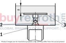
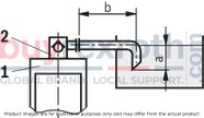
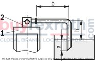
Size of the filling tank at least 1.5 x cylinder content
Flow ‒ case of application 4 (A to B)
Flow ‒ case of application 5 (A to B)
Notice!
An underdimensioned prefill valve and/or an underdimensioned line leads to gas leaks from the hydraulic fluid with corresponding consequences and often to long-term damage at the cylinder seals.
For boundary areas, please ask us!
Information on case of application 1 to 5
For limit areas, please contact us. It is often enough, to select a pipeline which is one size larger.
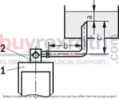
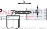
1 |
Cylinders |
2 |
Prefill valve |
3 |
This sheet is not included in the scope of delivery. With smaller tank dimensions and minimum hydraulic fluid level (a), it prevents the formation of tunnels. |
a |
at least 300 mm with extended cylinder |
b |
up to 1000 mm with the specified maximum flows |
c |
h ≤ 500 mm |
h |
300 mm ≤ h < 500 mm |
For applications outside these parameters, please consult us!
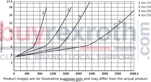
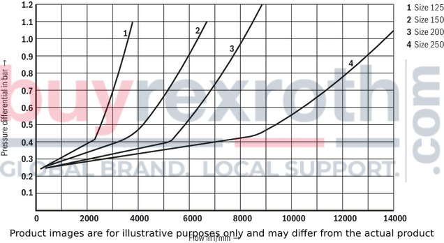
(measured with HLP46, ϑOil = 40 ±5 °C)
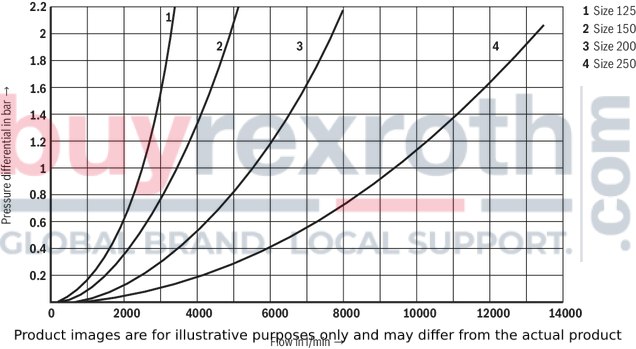
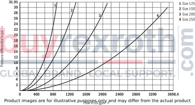
Δp-qv characteristic curves – NG125 … 250 (A → B)
Δp-qv characteristic curves – NG125 … 250 (B → A)
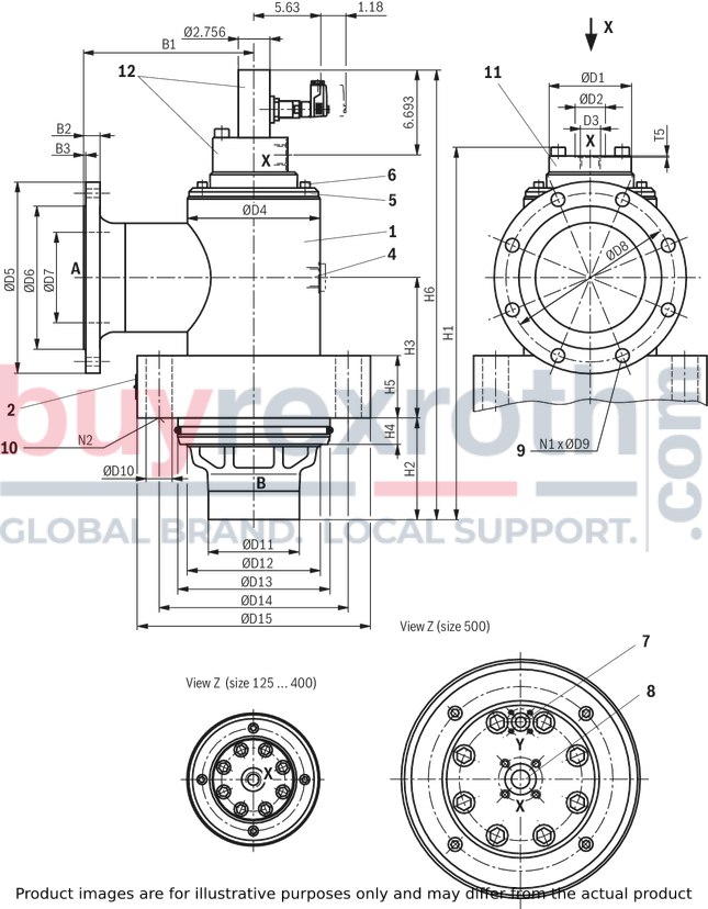
Version "A" and "B" (NG125 to 400)
Version "A" and "B" (NG500)
Version "K" (NG125 to 400)
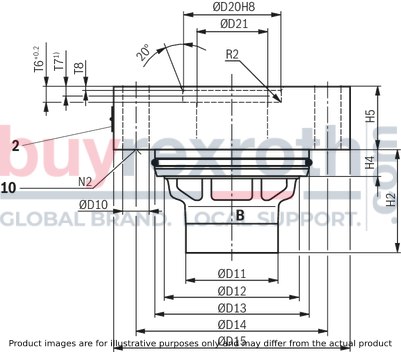
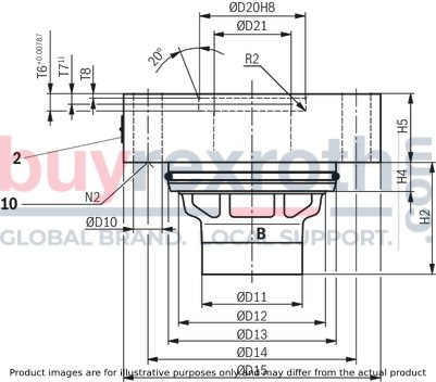
Version "A", flange connection
Poppet geometry and determination of the minimum pilot pressure
Dimensions in mm
Dimensions in mm
Modification from type of connection „A“ to „B“
Loosen the mounting screws (6) Remove the ring (5) Remove the housing (1)Rotate the housing (1)
Loosen the mounting screws (6) Rotate the housing (1) Tighten the mounting screws (6)Version "B", tank installation
Modification from type of connection „B“ to type of connection „K“
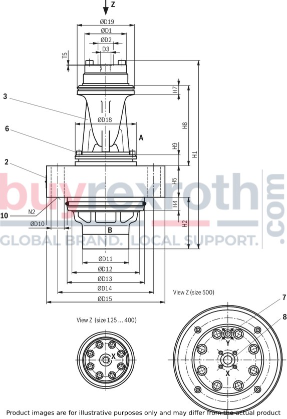
Loosen the mounting screws (6) Remove the control cylinder (3)Version "A" and "B"
Version "K", cartridge valve without control spool
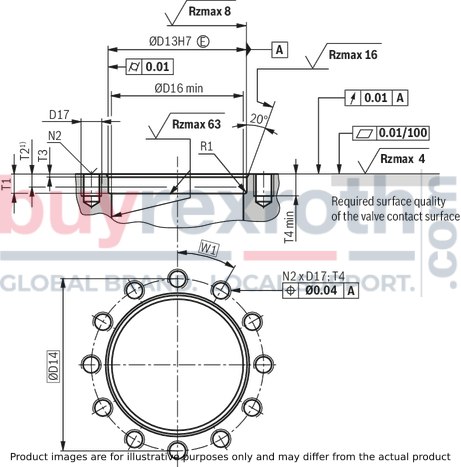
Dimensions in mm
1) | 1) Depth of fit |
Control cover with remote control port
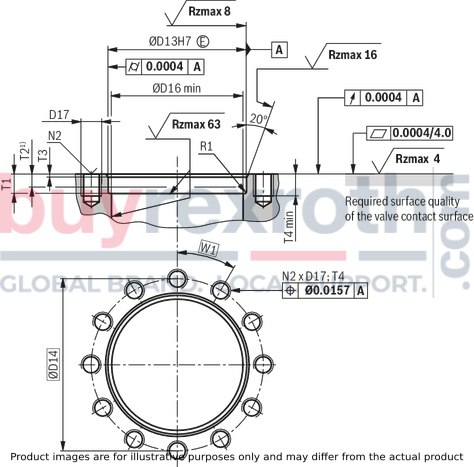
Dimensions in mm
1) | 1) Depth of fit |
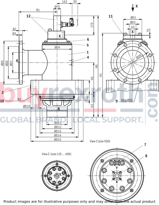
1 |
Housing with low-pressure flange, continuously rotatable |
2 |
Name plate |
3 |
Control cylinder |
4 |
Port G1 1/2; tightening torque MA = 300 Nm ±10 % |
5 |
Ring |
6 |
Mounting screws |
7 |
Port Y; connection flange on request |
8 |
Port X; connection flange on request |
9 N1 |
Number of the flange mounting screws evenly arranged at the circumference (type of connection "A") |
10 N2 |
Number of the valve mounting screws evenly arranged at the circumference |
11 |
Version "without position switch" |
12 |
Version "Q2G24Z" |
Dimensions in mm
1) | 1) Depth of fit |
Dimensions in mm
1) | 1) Depth of fit |
Notice!
Valve contact face (e.g. pressing cylinders, bearing structures, etc.) must be sufficiently rigid!
The prefill valve must not be loaded by bending!
Dimensions
NG |
B1 |
B2 |
B3 |
ØD1 |
ØD2 |
D3 |
ØD4 |
ØD5 |
ØD6 |
ØD7 |
ØD8 |
ØD9 |
ØD10 |
ØD11 |
ØD12 |
ØD13 |
ØD14 |
ØD15 |
ØD16 |
D17 1) |
ØD18 |
ØD19 |
ØD20 |
ØD21 |
H1 |
H2 |
H3 |
H4 |
H5 |
H6 |
H7 |
H8 |
H9 |
N1 |
N2 |
T1 |
T2 2) |
T3 |
T4 |
T5 |
T6 |
T7 |
T8 |
R1 |
R2 |
W1 |
mm |
mm |
mm |
mm |
mm |
mm |
mm |
mm |
mm |
mm |
mm |
mm |
mm |
mm |
mm |
mm |
mm |
mm |
mm |
mm |
mm |
mm |
mm |
mm |
mm |
mm |
mm |
mm |
mm |
mm |
mm |
mm |
mm |
mm |
mm |
mm |
mm |
mm |
mm |
mm |
mm |
mm |
mm |
° |
|||
125 | 210 | 22 | 3 | 110 | 42 | G3/4 | 178 | 250 | 188 | 132 | 210 | 18 | 33 | 120 | 175 | 200 | 250 | 310 | 180 | M30 | 159 | 156 | 130 | 105 | 490 | 136 | 185 | 35 | 80 | 515 | 25 | 207 | 28 | 8 | 12 | 37 | 26 | 5 | 40 | 1 | 14 | 12 | 3 | 3 | 0.5 | 30 |
150 | 250 | 22 | 3 | 130 | 42 | G3/4 | 229 | 285 | 212 | 159 | 240 | 22 | 40 | 145 | 220 | 250 | 310 | 380 | 230 | M36 | 200 | 195 | 160 | 130 | 604 | 160 | 220 | 35 | 90 | 603 | 26 | 248 | 31 | 8 | 12 | 37 | 26 | 5 | 60 | 1 | 14 | 12 | 3 | 3 | 0.5 | 30 |
200 | 275 | 24 | 3 | 150 | 47 | - | 273 | 340 | 268 | 207 | 295 | 22 | 40 | 155 | 265 | 290 | 350 | 420 | 270 | M36 | 235 | 230 | 185 | 155 | 695 | 180 | 255 | 35 | 100 | 671 | 27 | 298 | 36 | 12 | 15 | 37 | 26 | 5 | 50 | 1 | 14 | 12 | 3 | 3 | 0.5 | 24 |
250 | 330 | 26 | 3 | 190 | 58 | G1 1/4 | 356 | 405 | 320 | 260 | 355 | 26 | 46 | 180 | 350 | 380 | 445 | 530 | 355 | M42 | 315 | 310 | 250 | 206 | 835 | 240 | 320 | 55 | 120 | 756 | 38 | 379 | 44 | 12 | 18 | 57 | 42 | 8 | 60 | 1 | 21 | 19 | 4.5 | 5 | 1.6 | 20 |
300 | 380 | 28 | 4 | 225 | 58 | G1 1/4 | 419 | 460 | 378 | 310 | 410 | 26 | 46 | 220 | 420 | 450 | 525 | 610 | 425 | M42 | 375 | 370 | 300 | 255 | 1085 | 305 | 390 | 55 | 160 | 935 | 38 | 442 | 59 | 12 | 24 | 57 | 42 | 8 | 75 | 1 | 21 | 19 | 4.5 | 5 | 1.6 | 15 |
350 | 440 | 30 | 4 | 275 | 65 | G1 1/2 | 508 | 520 | 438 | 340 | 470 | 26 | 55 | 295 | 515 | 550 | 640 | 750 | 520 | M52 | 455 | 450 | 350 | 305 | 1259 | 360 | 460 | 55 | 200 | 1045 | 50 | 500 | 60 | 16 | 24 | 57 | 42 | 8 | 80 | 1 | 30 | 27 | 8 | 5 | 1.6 | 15 |
400 | 530 | 32 | 4 | 320 | 65 | G1 1/2 | 572 | 580 | 490 | 390 | 525 | 30 | 68 | 345 | 600 | 625 | 720 | 850 | 605 | M64 | 530 | 525 | 400 | 355 | 1463 | 423 | 510 | 55 | 210 | 1195 | 63 | 577 | 80 | 16 | 20 | 57 | 42 | 8 | 95 | 1 | 30 | 27 | 6 | 5 | 1.6 | 18 |
500 | 620 | 34 | 4 | 398 | - | - | 802 | 715 | 610 | 492 | 650 | 33 | 68 | 450 | 770 | 800 | 940 | 1070 | 785 | M64 | 750 | 745 | - | - | 1750 | 700 | 600 | 55 | 250 | 1290 | 70 | 686 | 90 | 20 | 24 | 60 | 45 | 10 | 110 | 2 | - | - | - | 5 | - | 15 |
1) | In earlier data sheet versions, fine threads were moreover specified. Please note when selecting the mounting screws! |
2) | Depth of fit |
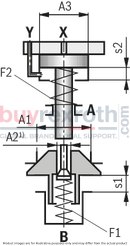
Poppet geometry and determination of the minimum pilot pressure – Version "A" and "B"
1) | Not applicable for version "without pre-decompression" (SF...0...) |
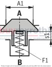
Poppet geometry and determination of the minimum pilot pressure – Version "K"
A1 |
Effective area of the main poppet |
A2 |
Effective area of the pilot poppet |
A3 |
Effective area of the control spool |
s1 |
Stroke of the main poppet |
s2 |
Stroke of the control spool |
F1 |
Spring force of the valve spring |
F2 |
Spring force of the compression spring of the control spool |
Vst X |
Pilot oil volume for opening the valve |
Vst Y |
Pilot oil volume for closing the valve |
pSt |
Pilot pressure at port X |
pB |
System pressure at port B |
Example: Type SF 300 ...
pB = 30 bar;
pSt = 4.0 x 30 bar = 120 bar
NG |
A1 |
A2 1) |
A3 |
s1 |
s2 |
F1 |
F2 |
VstX |
Vst Y |
Unchecking ratio |
|
cm² |
cm² |
cm² |
mm |
mm |
N |
N |
cm³ |
cm³ |
|||
125 | 101 | 2.5 | 24.6 | 28 | 25 | 220 … 360 | 780 … 2,340 | 62 | - | 4.1 | 0.1 |
150 | 153.9 | 3.8 | 38.5 | 35 | 29 | 350 … 570 | 1,530 … 3,550 | 112 | 4 | 0.1 | |
200 | 216.4 | 4.9 | 50.3 | 42 | 34 | 490 … 760 | 1,920 … 4,540 | 171 | 4.3 | 0.1 | |
250 | 373.3 | 9.6 | 95 | 53 | 41 | 870 … 1,460 | 4,160 … 7,260 | 390 | 3.9 | 0.1 | |
300 | 572.6 | 13.9 | 143.1 | 63 | 48 | 1,490 … 2,630 | 6,080 … 11,040 | 687 | 4 | 0.1 | |
350 | 826.6 | 21.2 | 213.8 | 78 | 58 | 2,180 … 3,880 | 9,490 … 15,600 | 1240 | 3.9 | 0.1 | |
400 | 1158 | 32.2 | 314.2 | 93 | 68 | 3,310 … 6,230 | 13,900 … 22,570 | 2136 | 3.7 | 0.1 | |
500 | 1948 | 49 | 490.9 | 140 | 100 | 6,520 … 13,800 | - | 4909 | 1767 | 4 | 0.1 |
1) | Not applicable for version "without pre-decompression" (SF...0...) |
2) | Without pre-decompression |
3) | With pre-decompression |
Related Products
R900313184
$585.23 USD
R900903463
$513.00 USD
R978034157
$696.00 USD
R901338532
$4,948.00 USD
R978036576
$2,070.00 USD