***Disclaimer: The following summary contains information gathered from various sources such as product descriptions, technical specifications and catalogs. While efforts have been made to provide accurate details, inaccuracies may occur. It is advised to verify all information by contacting Bosch Rexroth directly.***
The Bosch Rexroth 4WH 10 H4X/ (R900474423) is a high-performance directional spool valve designed for controlling the start, stop, and direction of flow in hydraulic systems. It is characterized by its hydraulic actuation and is part of the WH valve series. This specific model features spring centering of the control spool, ensuring that the main control spool is held in the zero position by two return springs when there is no pilot pressure. The spring chambers are connected to ports X and Y through a diversion plate, which facilitates the movement of the spool to the switching position when pilot pressure is applied.
The valve's design allows for external pilot oil supply and return via channels X and Y, ensuring efficient operation. It has been engineered for subplate mounting with a porting pattern that adheres to ISO standards. The 4WH 10 H4X/ offers versatility with options such as stroke setting, spool position monitoring, and it can be configured in 3 or 4-way versions.
This model from Bosch Rexroth comes with a size designation of 10 and belongs to component series X (which includes series X1, X2, X3). It can withstand a maximum operating pressure of up to 315 bar and can handle a maximum flow rate of up to l/min. Its robust construction makes it suitable for various applications requiring precise hydraulic flow control within an industrial setting. The unit's reliability and performance are underscored by Bosch Rexroth's commitment to quality in hydraulic components manufacturing.
$872.00 USD
More are expected on June 18, 2026
Status: This product is temporarily out of stock.
Qty: Delivered as early as June 18, 2026 when ordered in
This product is eligible for factory repair.
Type of actuation: (external pilot control): Hydraulic For subplate mounting Porting pattern according toISO 4401 4/3-, 4/2- or 3/2-way version Spring or pressure centering, spring end position or hydraulic end position Optional versions:
- Stroke setting and/or spool position monitoring
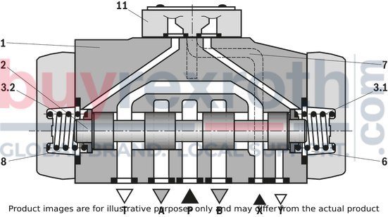
Valve type WH is a directional spool valve with hydraulic actuation. It controls the start, stop and direction of a flow. The directional valve basically consists of the valve housing (1), the main control spool (2), one or two return springs (3.1) and (3.2) at valves with spring return or spring centering as well as the diversion plate (11). The main control spool (2) is actuated directly by pressurization. The main control spool (2) is held in zero or initial position by springs or pressurization. Pilot oil supply and return are external (see pilot oil supply).
4/3 directional valve with spring centering of the control spool
With this version, the main control spool (2) is held in zero position by two return springs (3.1) and (3.2). The two spring chambers (6) and (8) are connected to ports X and Y via the diversion plate (11). With pilot pressure loading of one of the two front sides of the main control spool (2), the spool is moved to the switching position. In the valve, the required ports are connected in this way. The spring on the opposite side returns the spool to the zero or initial position at pressure relief of the pressurized control spool area.
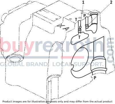
Pilot oil supply (schematic illustration)
NG10
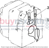
Pilot oil supply (schematic illustration)
NG16
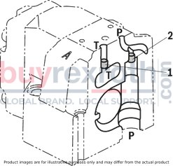
Pilot oil supply (schematic illustration)
NG25 („W.H 22“)

Pilot oil supply (schematic illustration)
NG25 („W.H 25“)
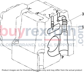
Pilot oil supply (schematic illustration)
Size 32
|
Pilot oil supply |
Pilot oil return |
||
|
External |
2, 3 closed |
External |
1 closed |
|
Internal |
2, 3 open |
Internal |
1 open |
|
1 |
Plug screw M6 according to DIN 906, wrench size 3 - Pilot oil return |
|
2 |
Plug screw M12 x 1.5 according DIN 906, wrench size 6 |
|
3 |
Plug screw M12 x 1.5 according DIN 906, wrench size 6 |
Type WH…
The pilot oil supply and return is implemented externally via channel X and Y.
|
01 |
02 |
03 |
04 |
05 |
06 |
07 |
08 |
09 |
10 |
11 |
12 |
13 |
14 |
15 |
||
|
WH |
/ |
/ |
* |
|
01 |
up to 280 bar |
no code |
|
02 |
3-way version |
3 |
|
4-way version |
4 |
|
|
Type of actuation |
||
|
03 |
hydraulic |
WH |
|
Size |
||
|
04 |
NG10 |
10 |
|
NG16 |
16 |
|
|
NG25 (version "WH 22") |
22 |
|
|
NG25 (version "WH 25") |
25 |
|
|
Size 32 |
32 |
|
|
Spool return in the main valve |
||
|
05 |
by means of springs |
no code |
|
hydraulic 1) |
H |
|
|
06 |
Symbols; for the possible version, see "Symbols/Circuit diagrams" |
|
|
07 |
Component series 40 … 49 (40 … 49: unchanged installation and connection dimension) – NG10 |
4X |
|
Component series 60 … 69 (60 … 69: unchanged installation and connection dimension) – NG25 ("WH 25") and NG32 |
6X |
|
|
Component series 70 … 79 (70 … 79: unchanged installation and connection dimension) – NG16 (from series 72) andNG25 ("WH 22") |
7X |
|
|
Pilot oil flow |
||
|
08 |
External pilot oil supply, external pilot oil return 2) |
no code |
|
Switching time adjustment |
||
|
09 |
without switching time adjustment |
no code |
|
Switching time adjustment as supply control |
S |
|
|
Switching time adjustment as discharge control |
S2 |
|
|
Corrosion resistance (outside) |
||
|
10 |
None (valve housing primed) |
no code |
|
Improved corrosion protection (240 h salt spray test according to EN ISO 9227) |
J3 |
|
|
Spool position monitoring |
||
|
11 |
Without position switch |
no code |
|
Monitored spool position “a” |
QMAG24 |
|
|
Monitored spool position “b” |
QMBG24 |
|
|
monitored spool position "a" and "b" |
QMABG24 |
|
|
Monitored rest position |
QM0G24 |
|
|
Stroke setting |
||
|
12 |
For ordering code, see dimesnions |
|
|
preload valve (not for NG10) 2) |
||
|
13 |
without pressure reducing valve |
no code |
|
with pressure reducing valve |
D3 |
|
|
Seal material |
||
|
14 |
NBR seals |
no code |
|
FKM seals |
V |
|
|
Observe compatibility of seals with hydraulic fluid used. (Other seals upon request) |
||
|
15 |
Further details in the plain text |
* |
| 1) – 2 spool positions (hydraulic end position): only symbols C, D, K, Z, Y | |
| – 3 switching positions (hydraulically centered): only NG16, NG25 ("4W.H 25") and NG32 | |
| 2) Pilot oil supply X or return Y external: | |
| – Minimum pilot pressure: please observe Technical data! | |
| – Maximum pilot pressure: please observe Technical data! | |
general
|
Size |
10 | 16 | 25 (WH 22) | 25 (WH 25) | 32 | ||
|
Weight (approx.) |
Valve witch hydraulic actuation (type WH...) |
kg |
5.5 | 7.3 | 10.5 | 16.5 | 39.5 |
|
Switching time adjustment "S" and "S2" |
kg |
0.8 | |||||
|
Pressure reducing valve "D3" |
kg |
0.4 | |||||
|
Installation position |
Any; horizontal with valves with hydraulic control spool return "H" and symbol A, B, C, D, K, Z, Y. With suspended installation, higher sensitivity to contamination – horizontal is recommended. | ||||||
|
Ambient temperature range |
Standard version |
°C |
-20 … +70 | ||||
|
Storage temperature range |
°C |
+5 … +40 | |||||
|
Surface protection |
Valve body |
Coating, layer thickness max. 100 μm | |||||
|
MTTFD values according to EN ISO 13849 |
Years |
150 | |||||
hydraulic
|
Size |
10 | 16 | 25 (WH 22) | 25 (WH 25) | 32 | |||
|
Maximum operating pressure |
Port P |
bar |
280 | |||||
|
Port A |
bar |
280 | ||||||
|
Port B |
bar |
280 | ||||||
|
Port T |
External pilot oil return Y |
bar |
280 | 250 | ||||
|
Port Y |
Pilot oil return, external |
bar |
250 | 210 | 250 | |||
|
Hydraulic fluid |
see table | |||||||
|
Hydraulic fluid temperature range |
NBR seals 1) |
°C |
-20 … +80 | |||||
|
FKM seals 1) |
°C |
-15 … +80 | ||||||
|
HFC hydraulic fluid |
-20 … +50 °C | |||||||
|
Viscosity range |
mm²/s |
2.8 … 500 | ||||||
|
Maximum admissible degree of contamination of the hydraulic fluid 2) |
Class 20/18/15 according to ISO 4406 (c) | |||||||
|
Maximum pilot pressure |
bar |
250 | 210 | 250 | ||||
|
Minimum pilot pressure |
Pilot oil supply X external or internal (with symbols D, K, E, J, L, M, Q, R, U, W) |
2-spool position valve, hydraulic end position |
bar |
7 | 14 | 8 | 5 | |
|
Internal pilot oil supply X (with symbols C, F, G, H, P, T, V, Z, S) |
bar |
7.5 3) | 4.5 4) 5) | 4.5 5) | ||||
|
Pilot volume for switching process |
3-spool position valve, spring-centered |
cm³ |
2.04 | 5.72 | 7.64 | 14.2 | 29.4 | |
|
2-spool position valve |
cm³ |
4.08 | 11.45 | 15.28 | 28.4 | 58.8 | ||
|
3-spool position valve, pressure-centered |
from zero position in switching position “a” |
cm³ |
- | 2.83 | - | 7.15 | 14.4 | |
|
from switching position “a” in zero position |
cm³ |
- | 5.72 | - | 14.18 | 29.4 | ||
|
from zero position in switching position “b” |
cm³ |
- | 5.72 | - | 14.18 | 29.4 | ||
|
from switching position “b” in zero position |
cm³ |
- | 8.55 | - | 19.88 | 43.8 | ||
|
Pilot flow for shortest switching time, approx. |
l/min |
35 | 45 | |||||
| 1) | If type WH is used in potentially explosion-proof areas, see data sheet 07011. |
| 2) | The cleanliness classes specified for the components must be adhered to in hydraulic systems. Effective filtration prevents faults and simultaneously increases the life cycle of the components. For the selection of the filters, see www.boschrexroth.com/filter. |
| 3) | For symbols C, F, G, H, P, T, V, Z, an internal pilot oil supply is only possible if the flow from P → T in the central position (for 3-spool position valve) or while crossing the central position (for 2-spool position valve) is so large that the pressure differential of P → T reaches a value of at least 6.5 bar. |
| 4) | Spool S only for NG16 |
| 5) | For spools C, F, G,J, H, P, T, V, Z, S – by means of preload valve (not NG10) or correspondingly high flow. (Determination of the required flow, see preload valve) |
Free flow cross-sections in zero position with spools Q, V and W
|
Size |
10 | 16 | 25 (WH 22) | 25 (WH 25) | 32 | ||
|
Spool Q |
A – T; B – T |
mm² |
13 | 32 | 78 | 83 | 78 |
|
Spool V |
P – A |
mm² |
13 | 32 | 73 | 83 | 73 |
|
A – T; B – T |
mm² |
13 | 32 | 84 | 83 | 84 | |
|
Spool W |
A – T; B – T |
mm² |
2.4 | 6 | 10 | 14 | 20 |
|
Hydraulic fluid |
Classification |
Suitable sealing materials |
Standards |
Data sheet |
|
|
Mineral oil |
HL, HLP, HLPD, HVLP, HVLPD |
NBR, FKM |
DIN 51524 |
90220 |
|
|
Bio-degradable |
Insoluble in water |
HETG |
FKM |
ISO 15380 |
90221 |
|
HEES |
FKM |
||||
|
Soluble in water |
HEPG |
FKM |
ISO 15380 |
||
|
Flame-resistant |
Water-free |
HFDU (glycol base) |
FKM |
ISO 12922 |
90222 |
|
HFDU (ester base) |
FKM |
||||
|
HFDR |
FKM |
||||
Important notice on hydraulic fluids:
For more information and data on the use of other hydraulic fluids, please refer to the data sheets above or contact us. There may be limitations regarding the technical valve data (temperature, pressure range, life cycle, maintenance intervals, etc.). The ignition temperature of the hydraulic fluid used must be 50 K higher than the maximum solenoid surface temperature.
• Bio-degradable and flame-resistant:
If these hydraulic fluids are used, small amounts of dissolved zinc may get into the hydraulic system (700 mg zinc per pole tube).
Inductive position switch type QM: electrical connection
The electric connection is realized via a 4-pole mating connector (separate order) with connection thread M12 x 1.
electrical
|
Connection voltage (DC voltage) |
V |
24 | ||
|
Voltage tolerance (connection voltage) |
+30 %/-15 % | |||
|
Admissible residual ripple |
% |
≤ 10 | ||
|
Max. load capacity |
mA |
400 | ||
|
Switching outputs 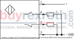
|
PNP transistor outputs, load between switching outputs and GND | |||
|
Pinout 
|
1 |
V |
24 | |
|
2, 4 |
Switching output |
mA |
400 | |
|
3 |
Earthing (GND) |
V |
0 |
For applications outside these parameters, please consult us!
(measured with HLP46, ϑOil = 40 °C ±5 °C)
NG10
Δp-qV characteristic curves

|
Symbol |
Spool position |
Zero position |
|||||
|
P – A |
P – B |
A – T 1) |
B – T 1) |
A – T |
B – T |
P – T |
|
|
E, Y, D, Q, V, W, Z |
1 |
1 |
3 |
5 |
|||
|
F |
1 |
3 |
1 |
4 |
3 |
– |
6 |
|
G, T |
4 |
2 |
4 |
7 |
– |
– |
8 |
|
H, C |
3 |
3 |
1 |
7 |
1 |
5 |
5 |
|
J, K |
1 |
2 |
1 |
6 |
|||
|
L |
2 |
2 |
1 |
4 |
2 |
– |
– |
|
M |
3 |
3 |
2 |
5 |
|||
|
P |
3 |
1 |
2 |
7 |
– |
5 |
7 |
|
R |
1 1 |
2 |
3 |
– |
|||
|
U |
2 |
2 |
3 |
6 |
– |
6 |
– |
|
A, B |
1 |
1 1 |
– |
– |
|||
| 1) | The pressure differential refers to the use of port T. If port T1 is additionally used,the pressure differential maybe lower. If only port T1 is used, the relations A – T and B – T may be reversed. |
Performance limits: (measured with HLP46, ϑOil = 40 °C ±5 °C)
NG10
|
2-spool position valve – qV maxin l/min |
|||||
|
Symbol |
Operating pressure pmax in bar |
||||
|
70 |
140 |
210 |
280 |
350 |
|
|
X external – spring end position in the main valve1) (with ppilot min = 12 bar) |
|||||
|
C, D, K, Y, Z |
160 |
160 |
160 |
160 |
160 |
|
X external – hydraulic end position in the main valve |
|||||
|
HC, HD, HK, HZ, HY |
160 |
160 |
160 |
160 |
160 |
| 1) | If the specified flow values are exceeded, the function of the return spring is no longer guaranteed if the pilot pressure fails! |
NG10
|
3-spool position valves – qV max in l/min |
|||||
|
Symbol |
Operating pressure pmax in bar |
||||
|
70 |
140 |
210 |
280 |
350 |
|
|
X external – spring-centered |
|||||
|
E, J, L, M, Q, U, V, W, R |
160 |
160 |
160 |
160 |
160 |
|
F, P |
160 |
120 |
100 |
90 |
90 |
|
G, T |
160 |
160 |
160 |
130 |
120 |
|
H |
160 |
160 |
120 |
110 |
100 |
(measured with HLP46, ϑOil = 40 °C ±5 °C)
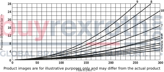
NG16
Δp-qV characteristic curves
|
Symbol |
Spool position |
Zero position |
|||||
|
P –A |
P – B |
A – T |
B – T |
P – T |
A – T |
B – T |
|
|
D, E, Y |
1 |
1 |
3 |
3 |
|||
|
F |
1 |
2 |
5 |
5 |
4 |
3 |
– |
|
G |
4 |
1 |
5 |
5 |
7 |
– |
– |
|
C, H |
1 |
1 |
5 |
6 |
2 |
4 |
4 |
|
K, J |
2 |
2 |
6 |
6 |
– |
3 |
– |
|
L |
2 |
2 |
5 |
4 |
– |
3 |
– |
|
M |
1 |
1 |
3 |
4 |
|||
|
P |
2 |
1 |
3 |
6 |
5 |
– |
– |
|
Q |
1 |
1 |
6 |
6 |
|||
|
R |
2 |
4 |
7 |
– |
|||
|
S |
3 |
3 |
3 |
– |
9 |
– |
– |
|
T |
4 |
1 |
5 |
5 |
7 |
– |
– |
|
U |
2 |
2 |
3 |
6 |
|||
|
V, Z |
1 |
1 |
6 |
6 |
10 |
8 |
8 |
|
W |
1 |
1 |
3 |
4 |
|||
Performance limits: (measured with HLP46, ϑOil = 40 °C ±5 °C)
NG16
|
2-spool position valve – qV maxin l/min |
|||||
|
Symbol |
Operating pressure pmax in bar |
||||
|
70 |
140 |
210 |
280 |
350 |
|
|
X external – spring end position in the main valve1) (with ppilot min = 12 bar) |
|||||
|
C, D, K, Y, Z |
300 |
300 |
300 |
300 |
300 |
|
X external – spring end position in the main valve |
|||||
|
C |
300 |
300 |
300 |
300 |
300 |
|
D, Y |
300 |
270 |
260 |
250 |
230 |
|
K |
300 |
250 |
240 |
230 |
210 |
|
Z |
300 |
260 |
190 |
180 |
160 |
|
X external – hydraulic end position in the main valve |
|||||
|
HC, HD, HK, HZ, HY |
300 |
300 |
300 |
300 |
300 |
| 1) | If the specified flow values are exceeded, the function of the return spring is no longer guaranteed if the pilot pressure fails! |
NG16
|
3-spool position valves – qV max in l/min |
|||||
|
Symbol |
Operating pressure pmax in bar |
||||
|
70 |
140 |
210 |
280 |
350 |
|
|
X external – spring-centered |
|||||
|
E, H, J, L, M, Q, U, W, R |
300 |
300 |
300 |
300 |
300 |
|
F, P |
300 |
250 |
180 |
170 |
150 |
|
G, T |
300 |
300 |
240 |
210 |
190 |
|
S |
300 |
300 |
300 |
250 |
220 |
|
V |
300 |
250 |
210 |
200 |
180 |
|
X external – pressure-centered (at minimum pilot pressure of 16 bar) |
|||||
|
all 1) |
300 |
300 |
300 |
300 |
300 |
| 1) | With symbol V, the pilot control valve is not required for flows >160 l/min. |
(measured with HLP46, ϑOil = 40 °C ±5 °C)
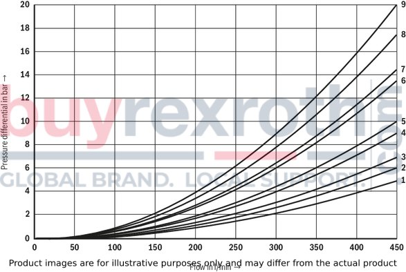
NG25 (type W.H 22)
Δp-qV characteristic curves
|
Symbol |
Spool position |
Symbol |
Zero position |
||||||
|
P – A |
P – B |
A – T |
B – T |
B – A |
A – T |
B – T |
P – T |
||
|
E, D |
2 |
2 |
3 |
5 |
– |
F |
2 |
– |
4 |
|
J, Q, K |
2 |
2 |
4 |
6 |
– |
G, T |
– |
– |
9 |
|
M, W |
1 |
1 |
3 |
5 |
– |
H |
– |
– |
3 |
|
H, V, C, Z |
1 |
1 |
4 |
6 |
– |
L |
7 |
– |
– |
|
F |
1 |
2 |
4 |
5 |
– |
U |
– |
6 |
– |
|
G |
3 |
4 |
5 |
6 |
– |
J |
8 |
8 |
– |
|
R |
1 |
2 |
2 |
– |
– |
P |
– |
4 |
6 |
|
L |
2 |
2 |
4 |
5 |
– |
V, Z |
– |
– |
8 |
|
U |
2 |
2 |
2 |
6 |
– |
||||
|
P |
2 |
2 |
2 |
7 |
– |
||||
|
T |
4 |
4 |
5 |
6 |
– |
||||
Performance limits: (measured with HLP46, ϑOil = 40 °C ±5 °C)
NG25 (type W.H 22)
|
2-spool position valve – qV maxin l/min |
|||||
|
Symbol |
Operating pressure pmax in bar |
||||
|
70 |
140 |
210 |
280 |
350 |
|
|
X external – spring end position in the main valve (with ppilot min = 11 bar / 14 bar) |
|||||
|
C, D, K, Y, Z |
450 |
450 |
450 |
450 |
450 |
|
X external – spring end position in the main valve 1) |
|||||
|
C |
450 |
450 |
320 |
250 |
200 |
|
D, Y |
450 |
450 |
450 |
400 |
320 |
|
K |
450 |
215 |
150 |
120 |
100 |
|
Z |
350 |
300 |
290 |
260 |
160 |
|
X external – hydraulic end position in the main valve |
|||||
|
HC, HD, HK, HZ, HY |
450 |
450 |
450 |
450 |
450 |
|
HC./O…, HD./O…, HK./O…, HZ./O… |
450 |
450 |
450 |
450 |
450 |
|
HC./OF…, HD./OF…, HK./OF…, HZ./OF… |
450 |
450 |
450 |
450 |
450 |
| 1) | If the specified flow values are exceeded, the function of the return spring is no longer guaranteed if the pilot pressure fails! |
NG25 (type W.H 22)
|
3-spool position valves – qV max in l/min |
|||||
|
Symbol |
Operating pressure pmax in bar |
||||
|
70 |
140 |
210 |
280 |
350 |
|
|
X external – spring-centered |
|||||
|
E, J, L, M, Q, U, W, R |
450 |
450 |
450 |
450 |
450 |
|
H |
450 |
450 |
300 |
260 |
230 |
|
G |
400 |
350 |
250 |
200 |
180 |
|
F |
450 |
270 |
175 |
130 |
110 |
|
V |
450 |
300 |
240 |
220 |
160 |
|
T |
400 |
300 |
240 |
200 |
160 |
|
P |
450 |
270 |
180 |
170 |
110 |
(measured with HLP46, ϑOil = 40 °C ±5 °C)
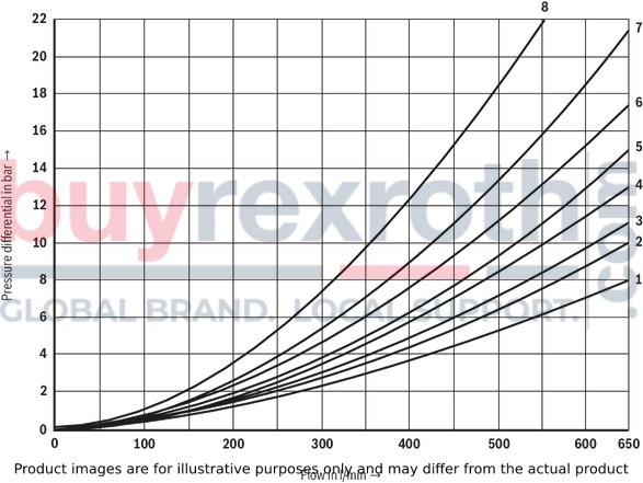
NG25 (type W.H 25)
Δp-qV characteristic curves
|
Symbol |
Spool position |
Zero position |
|||||
|
P – A |
P – B |
A – T 1) |
B – T 1) |
A – T |
B – T |
P – T |
|
|
E, Y, D |
1 |
1 |
3 |
4 |
|||
|
F |
1 |
1 |
2 |
4 |
2 |
– |
5 |
|
G, T |
1 |
1 |
2 |
5 |
– |
– |
7 |
|
H |
1 |
1 |
2 |
5 |
2 |
2 |
4 |
|
C |
1 |
1 |
2 |
5 |
|||
|
J |
1 |
1 |
2 |
5 |
6 |
5 |
– |
|
K |
1 |
1 |
2 |
5 |
|||
|
L |
1 |
1 |
2 |
4 |
5 |
– |
– |
|
M |
1 |
1 |
3 |
4 |
|||
|
P |
1 |
1 |
3 |
5 |
– |
3 |
5 |
|
Q |
1 |
1 |
2 |
3 |
|||
|
R |
1 |
1 |
3 |
– |
|||
|
U |
1 |
1 |
2 |
5 |
– |
5 |
– |
|
V |
1 |
1 |
2 |
5 |
8 |
7 |
– |
|
Z |
1 |
1 |
2 |
5 |
|||
|
W |
1 |
1 |
3 |
4 |
|||
|
8 Symbol R, spool position B – A |
|||||||
|
7 |
Spool type G |
Central position P – T |
|
8 |
Spool type T |
Central position P – T |
Performance limits: (measured with HLP46, ϑOil = 40 °C ±5 °C)
NG25 (type W.H 25)
|
2-spool position valve – qV maxin l/min |
|||||
|
Symbol |
Operating pressure pmax in bar |
||||
|
70 |
140 |
210 |
280 |
350 |
|
|
X external – spring end position in the main valve (with ppilotmin = 13 bar) |
|||||
|
C, D, K, Y, Z |
700 |
700 |
700 |
700 |
650 |
|
X external – spring end position in the main valve 1) |
|||||
|
C |
700 |
700 |
700 |
700 |
650 |
|
D, Y |
700 |
650 |
400 |
350 |
300 |
|
K |
700 |
650 |
420 |
370 |
320 |
|
Z |
700 |
700 |
650 |
480 |
400 |
|
X external – hydraulic end position in the main valve |
|||||
|
HC, HD, HK, HZ, HY |
700 |
700 |
700 |
700 |
700 |
|
HC./O…, HD./O…, HK./O…, HZ./O… |
700 |
700 |
700 |
700 |
700 |
|
HC./OF…, HD./OF…, HK./OF…, HZ./OF… |
700 |
700 |
700 |
700 |
700 |
| 1) | If the specified flow values are exceeded, the function of the return spring is no longer guaranteed if the pilot pressure fails! |
NG25 (type W.H 25)
|
3-spool position valves – qV max in l/min |
|||||
|
Symbol |
Operating pressure pmax in bar |
||||
|
70 |
140 |
210 |
280 |
350 |
|
|
X external – spring-centered |
|||||
|
E, L, M, Q, U, W |
700 |
700 |
700 |
700 |
650 |
|
G, T |
400 |
400 |
400 |
400 |
400 |
|
F |
650 |
550 |
430 |
330 |
300 |
|
H |
700 |
650 |
550 |
400 |
360 |
|
J |
700 |
700 |
650 |
600 |
520 |
|
P |
650 |
550 |
430 |
430 |
300 |
|
V |
650 |
550 |
400 |
350 |
310 |
|
R |
700 |
700 |
700 |
650 |
580 |
|
X external – pressure-centered (at minimum pilot pressure of 18 bar) |
|||||
|
E, F, H, J, L, M, P, Q, R, U, V, W |
700 |
700 |
700 |
700 |
650 |
|
G, T |
400 |
400 |
400 |
400 |
400 |
|
X external – pressure-centered (with pilot pressure > 30 bar) |
|||||
|
G, T |
700 |
700 |
700 |
700 |
650 |
(measured with HLP46, ϑOil = 40 °C ±5 °C)
Size 32
∆p-qv-characteristic curves – Symbol E, R and W

|
Symbol |
Spool position |
||||
|
P – A |
P – B |
A – T |
B – T |
B – A |
|
|
E |
4 |
4 |
3 |
2 |
– |
|
R |
4 |
4 |
3 |
– |
1 |
|
W |
4 |
4 |
3 |
2 |
– |
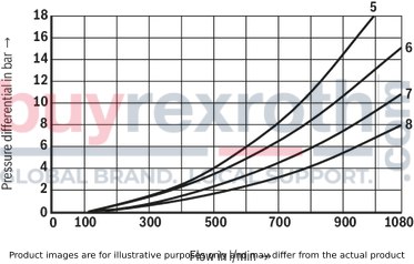
Size 32
∆p-qv- characteristic curves – Symbol G and T
|
Symbol |
Spool position |
||||
|
P – A |
P – B |
A – T |
B – T |
P – T |
|
|
G |
7 |
8 |
7 |
5 |
6 |
|
T |
7 |
8 |
7 |
5 |
6 |
Performance limits: (measured with HLP46, ϑOil = 40 °C ±5 °C)
Size 32
|
2-spool position valve – qV maxin l/min |
|||||
|
Symbol |
Operating pressure pmax in bar |
||||
|
70 |
140 |
210 |
280 |
350 |
|
|
X external – spring end position in the main valve (with ppilot min = 10 bar) |
|||||
|
C, D, K, Y, Z |
1100 |
1040 |
860 |
750 |
680 |
|
X external – spring end position in the main valve 1) |
|||||
|
C |
1100 |
1040 |
860 |
800 |
700 |
|
D, Y |
1100 |
1040 |
540 |
480 |
420 |
|
K |
1100 |
1040 |
860 |
500 |
450 |
|
Z |
1100 |
1040 |
860 |
700 |
650 |
|
X external – hydraulic end position in the main valve |
|||||
|
HC, HD, HK, HZ, HY |
1100 |
1040 |
860 |
750 |
680 |
| 1) | If the specified flow values are exceeded, the function of the return spring is no longer guaranteed if the pilot pressure fails! |
Size 32
|
3-spool position valves – qV max in l/min |
|||||
|
Symbol |
Operating pressure pmax in bar |
||||
|
70 |
140 |
210 |
280 |
350 |
|
|
X external – spring-centered |
|||||
|
E, J, L, M, Q, R, U, W |
1100 |
1040 |
860 |
750 |
680 |
|
G, T, H, F, P |
900 |
900 |
800 |
650 |
450 |
|
V |
1100 |
1000 |
680 |
500 |
450 |
|
X external – pressure-centered (at minimum pilot pressure of 8.5 bar) |
|||||
|
all |
1100 |
1040 |
860 |
750 |
680 |
At a higher tank pressure, the minimum pilot pressure has to be increased according to this diagram.
2 spool positions
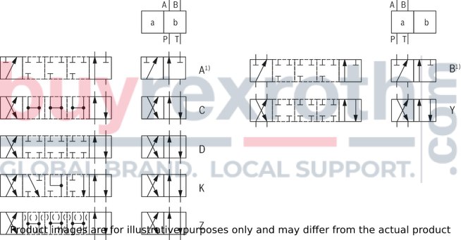
| 1) | Only for NG10 and 25 ("H-WEH 22") with 3/2-way version; if operating pressure > tank pressure, port T is to be used as a leakage port! |
|
Ordering code |
Type of actuation |
|
|
Symbol |
Spool return |
Type WH (hydraulic) |
|
A1), C, D, K, Z |
../.. |

|
|
..H../.. |

|
|
|
B1), Y |
../.. |

|
| 1) | Only for NG10 and 25 ("4W.H 22") with 3/2-way version; if operating pressure > tank pressure, port T is to be used as aleakage port! |
3 spool positions
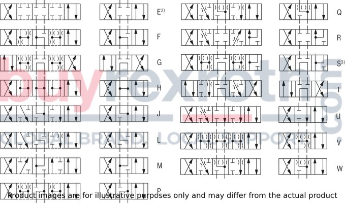
| 2) Example: Symbol E with actuating side “a” → ordering code ..EA.. | |
| 3) Symbol S only for NG16 |
|
Ordering code |
Type of actuation |
||
|
Symbol |
Actuating side |
Spool return |
Type WH (hydraulic) |
|
E, F, G, H, J, L, M, P, Q, R, S, T, U, V, W |
../.. |

|
|
|
..H../.. |

|
||
Inductive position switch type QM Switching logics
Version QMA
(Position switch on side B, monitored spool position of the main stage "a")
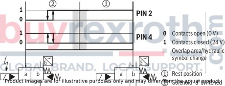
Version QMA
(Position switch on side B, monitored spool position of the main stage "a")
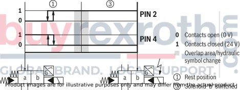
Version QMB
(Position switch on side A, monitored spool position of the main stage "b")
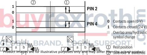
Version QMB
(Position switch on side A, monitored spool position of the main stage "b")

version QMAB
(Position switch on side A and B, monitored spool position "a" and "b")
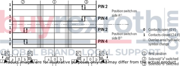
Version QM0
(Position switch on side A and B, monitored spool position "0")
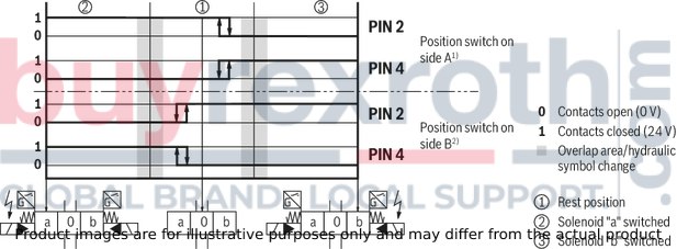
| 1) No signal change at the position switch on side B with spool position "a" | |
| 2) No signal change at the position switch on side A with spool position "b" |
Version QM0
(Position switch on side B, monitored spool position of the main stage "0")
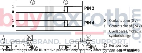
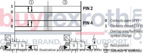
Version QM0
(Position switch on side A, monitored spool position of the main stage "0")
NG10
Dimensions in mm
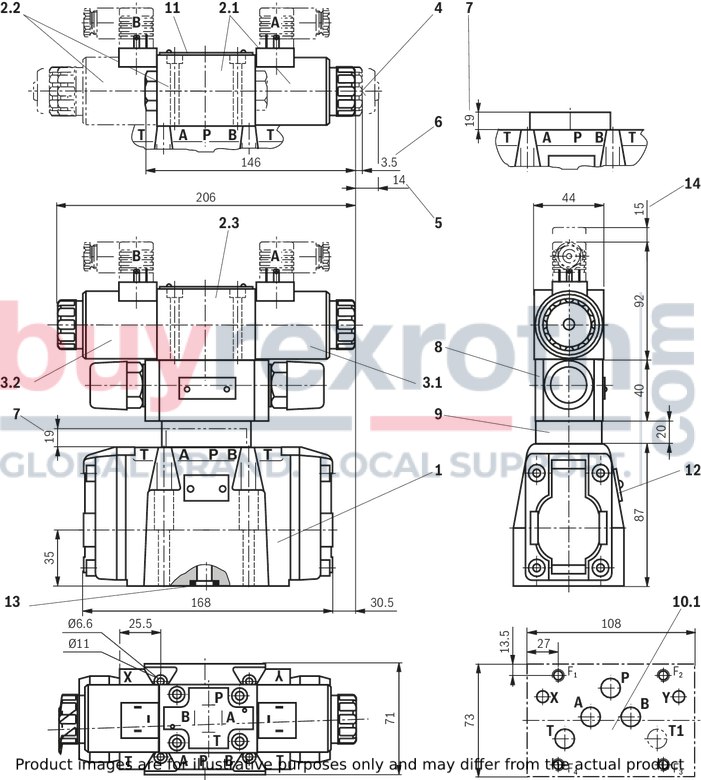

|
|
Required surface quality of the valve contact surface |
Notice:
The dimensions are nominal dimensions which are subject to tolerances.
|
1 |
Main valve |
|
7 |
Height of the diversion plate with hydraulic actuation |
|
10.1 |
machined valve contact surface; porting pattern according to ISO 4401-05-05-0-05 |
|
12 |
Name plate complete valve |
|
13 |
Seal rings |
NG16
Dimensions in mm
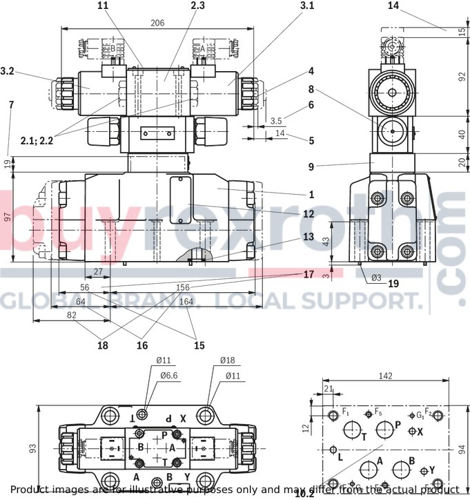

|
|
Required surface quality of the valve contact surface |
Notice:
The dimensions are nominal dimensions which are subject to tolerances.
|
1 |
Main valve |
|
7 |
Height of the diversion plate with hydraulic actuation |
|
10.2 |
machined valve contact surface; porting pattern according to ISO 4401-07-07-0-05 |
|
11 |
Name plate pilot control valve |
|
12 |
Name plate complete valve |
|
13 |
Seal rings |
|
15 |
2-spool position valves with spring end position in the main valve (spool symbols A, C, D, K, Z) |
|
16 |
2-spool position valves with spring end position in the main valve (spool symbols B, Y) |
|
17 |
3-spool position valves, spring-centered; |
|
18 |
3-spool position valves, pressure-centered |
|
19 |
Locking pin |
NG25 (type W.H 22)
Dimensions in mm
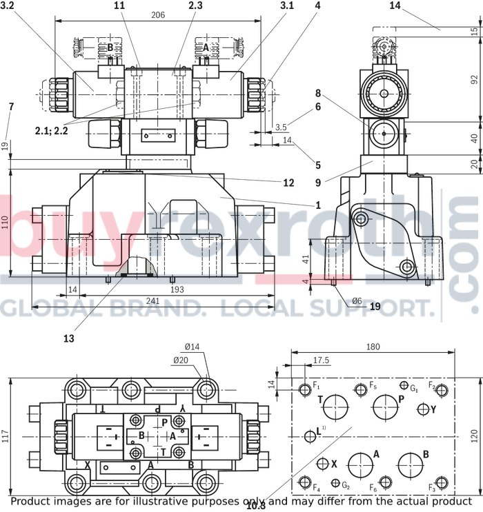
| 1) | Port L only for valves with pressure-centered zero position |

|
|
Required surface quality of the valve contact surface |
Notice:
The dimensions are nominal dimensions which are subject to tolerances.
|
1 |
Main valve |
|
7 |
Height of the diversion plate with hydraulic actuation |
|
10.3 |
machined valve contact surface; porting pattern according to ISO 4401-08-08-0-05 |
|
12 |
Name plate complete valve |
|
13 |
Seal rings |
|
19 |
Locking pin |
NG25 (type W.H 25)
Dimensions in mm
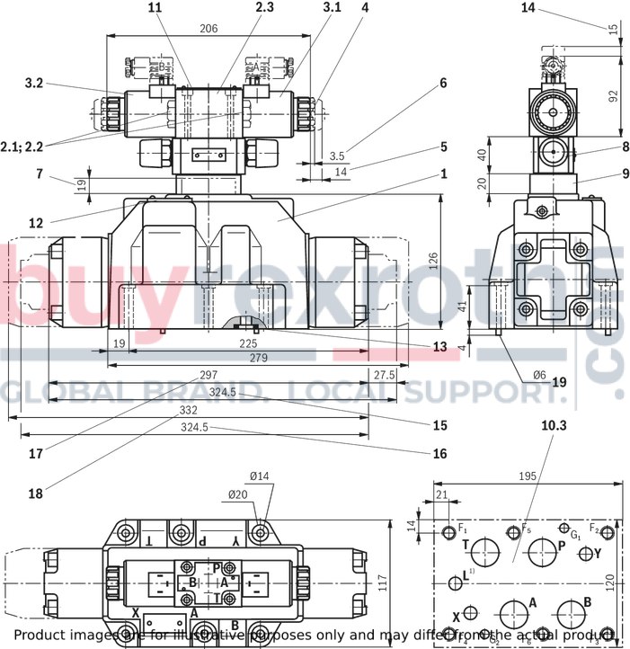
| 1) | Port L only for valves with pressure-centered zero position |

|
|
Required surface quality of the valve contact surface |
Notice:
The dimensions are nominal dimensions which are subject to tolerances.
|
1 |
Main valve |
|
7 |
Height of the diversion plate with hydraulic actuation |
|
10.3 |
machined valve contact surface; porting pattern according to ISO 4401-08-08-0-05 |
|
12 |
Name plate complete valve |
|
13 |
Seal rings |
|
15 |
2-spool position valves with spring end position in the main valve (spool symbols A, C, D, K, Z) |
|
16 |
2-spool position valves with spring end position in the main valve (spool symbols B, Y) |
|
17 |
3-spool position valves, spring-centered; |
|
18 |
3-spool position valve, pressure-centered |
|
19 |
Locking pin |
Size 32
Dimensions in mm
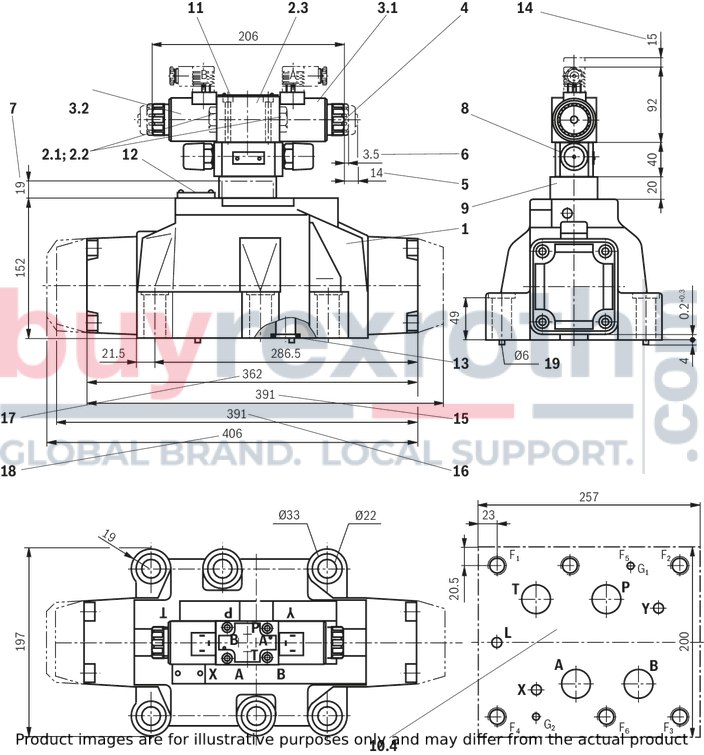

|
|
Required surface quality of the valve contact surface |
Notice:
The dimensions are nominal dimensions which are subject to tolerances.
|
1 |
Main valve |
|
7 |
Height of the diversion plate with hydraulic actuation |
|
10.4 |
machined valve contact surface; porting pattern according to ISO 4401-10-09-0-05 |
|
12 |
Name plate complete valve |
|
13 |
Seal rings |
|
15 |
2-spool position valves with spring end position in the main valve (spool symbols A, C, D, K, Z) |
|
16 |
2-spool position valves with spring end position in the main valve (spool symbols B, Y) |
|
17 |
3-spool position valves, spring-centered; |
|
18 |
3-spool position valve, pressure-centered |
|
19 |
Locking pin |
Subplates (separate order) with porting pattern according to ISO 4401 see data sheet 45100.
Valve mounting screws (separate order)
– NG10:
4 hexagon socket head cap screws, metric
ISO 4762 - M6 x 45 - 10.9-flZn-240h-L
(Friction coefficientμtotal = 0.09 to 0.14);
Tightening torque MA = 12.5 Nm ± 10%,
material no. R913000258
4 hexagon socket head cap screws UNC 1/4-20 UNC x 1 3/4″ ASTM-A574
upon request
– NG16:
4 hexagon socket head cap screws, metric
ISO 4762 - M10 x 60 - 10.9-flZn-240h-L
(friction coefficientμtotal = 0.09 to 0.14);
Tightening torque MA = 75 Nm ± 10%,
Material no. R913000116
2 hexagon socket head cap screws, metric
ISO 4762 - M6 x 60 - 10.9-flZn-240h-L
(Friction coefficient μtotal = 0.09 to 0.14);
Tightening torque MA = 12,5 Nm ± 10%,
material no. R913000115
4 hexagon socket head cap screws UNC 3/8-16 UNC x 2 1/4″ ASTM-A574
upon request
2 hexagon socket head cap screws UNC 1/4-20 UNC x 1/4″ ASTM-A574
upon request
– NG25:
6 hexagon socket head cap screws, metric
ISO 4762 - M12 x 60 - 10.9-flZn-240h-L
(friction coefficient μtotal = 0.09 to 0.14);
Tightening torque MA = 130 Nm ± 10%,
Material no. R913000121
6 hexagon socket head cap screws UNC 1/2-13 UNC x 2 1/2″ ASTM-A574
upon request
– NG32:
6 hexagon socket head cap screws, metric
ISO 4762 - M20 x 80 - 10.9-flZn-240h-L
(friction coefficient μtotal = 0.09 to 0.14);
Tightening torque MA = 430 Nm ± 10%,
Material no. R901035246
6 hexagon socket head cap screws UNC 3/4-10 UNC x 3 1/4″ ASTM-A574
upon request
Stroke setting, mounting options
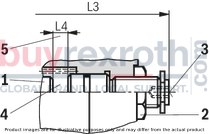
The stroke of the control spool is limited by the stroke setting (1). The control spool stroke is shortened by loosening the lock nut (2) and clockwise rotation of the adjustment spindle (3). The control chamber (4) must be depressurized for this.
|
NG |
L4 |
|
mm |
|
| 10 | 6.5 |
| 16 | 10 |
| 25 (WH 22) | 9.5 |
| 25 (WH 25) | 12.5 |
| 32 | 15 |
5 adjustment range
– NG10:
1 rotation = 1 mm adjustment travel
– NG16 to 32:
1 rotation = 1.5 mm adjustment travel
Stroke setting, mounting options
Stroke limitation on side A

Stroke setting, mounting options
Stroke limitation on side B
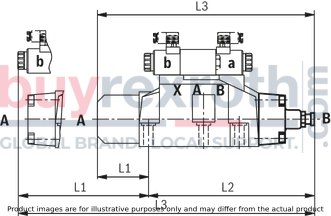
|
Mounting options |
Ordering code |
NG |
3-spool position valve 1) |
|||||
|
Spring-centered |
Pressure-centered |
|||||||
|
L1 (mm) |
L2 (mm) |
L3 (mm) |
L1 (mm) |
L2 (mm) |
L3 (mm) |
|||
|
Stroke setting on valve side A and B |
10 |
10 |
90 |
144 |
234 |
|||
|
16 |
100 |
200 |
300 |
|||||
|
25 2) |
96 |
241 |
337 |
|||||
|
25 3) |
123 |
276 |
399 |
|||||
|
32 |
133 |
344 |
477 |
|||||
|
Stroke setting on valve side A |
11 |
10 |
90 |
106 |
196 |
|||
|
16 |
100 |
156 |
256 |
|||||
|
25 2) |
96 |
193 |
289 |
|||||
|
25 3) |
123 |
225 |
348 |
|||||
|
32 |
133 |
287 |
420 |
|||||
|
Stroke setting on valve side B |
12 |
10 |
52 |
144 |
196 |
– |
– |
– |
|
16 |
56 |
200 |
256 |
81 |
200 |
281 |
||
|
25 2) |
48 |
241 |
289 |
– |
– |
– |
||
|
25 3) |
72 |
276 |
348 |
107 |
276 |
283 |
||
|
32 |
76 |
344 |
420 |
120 |
344 |
464 |
||
| 1) With symbol A only version "11", with symbol B only version "12" possible. |
|
2-spool position valve |
|||||||||||
|
Spring end position |
Hydraulic end position |
||||||||||
|
A, C, D, K, Z |
B, Y |
HC, HD, HK, HZ, HY |
|||||||||
|
Mounting options |
Ordering code |
NG |
L1 (mm) |
L2 (mm) |
L3 (mm) |
L1 (mm) |
L2 (mm) |
L3 (mm) |
L1 (mm) |
L2 (mm) |
L3 (mm) |
|
Stroke setting on valve side A and B |
10 |
10 |
90 |
144 |
234 |
90 |
144 |
234 |
90 |
144 |
234 |
|
16 |
– |
– |
– |
– |
– |
– |
100 |
200 |
300 |
||
|
25 1) |
96 |
241 |
337 |
96 |
241 |
337 |
96 |
241 |
337 |
||
|
25 2) |
– |
– |
– |
– |
– |
– |
123 |
276 |
399 |
||
|
32 |
– |
– |
– |
– |
– |
– |
133 |
344 |
477 |
||
|
Stroke setting on valve side A |
11 |
10 |
90 |
106 |
196 |
– |
– |
– |
90 |
106 |
196 |
|
16 |
100 |
180 |
280 |
– |
– |
– |
100 |
156 |
256 |
||
|
25 1) |
96 |
193 |
289 |
96 |
193 |
289 |
96 |
193 |
289 |
||
|
25 2) |
123 |
253 |
376 |
– |
– |
– |
123 |
225 |
348 |
||
|
32 |
133 |
316 |
449 |
– |
– |
– |
133 |
287 |
420 |
||
|
Stroke setting on valve side B |
12 |
10 |
52 |
144 |
196 |
52 |
144 |
196 |
52 |
144 |
196 |
|
16 |
– |
– |
– |
80 |
200 |
280 |
56 |
200 |
256 |
||
|
25 1) |
48 |
241 |
289 |
48 |
241 |
289 |
48 |
241 |
289 |
||
|
25 2) |
– |
– |
– |
100 |
276 |
376 |
72 |
276 |
348 |
||
|
32 |
– |
– |
– |
105 |
344 |
449 |
76 |
344 |
420 |
||
| 1) Version "W.H 22" | |
| 2) Version "W.H 25" |
Spool position monitoring
Inductive position switch type QM
Dimensions in mm
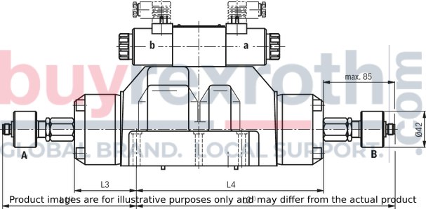
| 1) | Without mating connector |
Notice:
The dimensions are nominal dimensions which are subject to tolerances.
Switching time adjustment
Type 4WEH 10 ..4X/…S
Type 4WEH 10 ..4X/…S2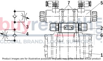
The switching time of the main valve (1) is influenced by using a twin throttle check valve (2) (type Z2FS 6; data sheet 27506).
Modification of supply (3) to discharge control (4):
Remove the pilot control valve (5) – The plate (6) to accept the seal rings stays in place – Turn the switching time adjustment (2) around its longitudinal axis and put it back, install the pilot control valve (5).
Notice:
The modification may only be performed by authorized specialists or at the factory!
"D3” pressure reducing valve
Type 4WEH 10 ..4X/…/..D3
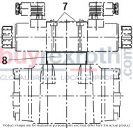
The pressure reducing valve (8) has to be used at a pilot pressure above 250 bar (with type 4WEH 22 …: 210 bar) and with version “H”.
The secondary pressure is kept at a constant level of 45 bar.
Notice:
If a pressure reducing valve "D3" (8) is used, a "B10" throttle insert has to be installed in channel P of the pilot control valve. The modification may only be performed by authorized specialists or at the factory!The stipulations of the Machinery Directive 2006/42/EC are to be adhered to! Please also note data sheet 08012 with information on MTTFd values and shock and vibration loads!


