


VT-HACD-1-1X/V0/1-P-0 KIT
Manufacturer: Bosch Rexroth
Material #: R978018202
Model : VT-HACD-1-1X/V0/1-P-0 KIT
| Qty | Price | Savings |
|---|---|---|
| 5+ | $0.00 USD | $0.00 USD |
This product is not available. CLICK HERE to create a support ticket for us to locate your part or a suitable replacement
The command value and controller card VT-HACD-1 is set up as printed circuit board in Europe format 100 x 160 mm, fitted on both sides.
A microcontroller controls the entire process, makes adjustments, establishes connections and realizes the closed control loops. Data for configuration, command values and parameters are stored in a FLASH in a non-volatile form.
The complete configuration is made by means of software, the card does not comprise jumpers or the like. For the configuration, the VT-HACD has to be connected to a PC via a serial interface (RS 232, 1:1 cable). The BODAC user interface is used for the entire configuration and also for the parameterization and diagnosis.
The configuration and thus the creation of applications are very simple - simply connect the pre-defined functional components. For this purpose, no programming knowledge is necessary.
2 different modes are available:
Mode 1 (not bus-enabled) – Block calls (condition as supplied)The 32 blocks can be called via the binary combination of the digital inputs DI1…DI5 + DI6 as "binary enable". This mode is functionally compatible with VT-SWKD.
Mode 3 (bus-enabled) – Structural editorThe structural editor is unlocked. Own motion sequences can be established. For this purpose, 32 blocks are available.
Each block contains: Command value, ramp times, (velocity +, velocity –, S share) and controller parameters.
Blocks are activated by setting trigger conditions: Setting digital inputs, comparing signals with freely definable thresholds or expiry of waiting times.
You can change to another mode by simply saving a corresponding parameter set which is included in the BODAC scope of delivery.
Signal linking
The VT-HACD has various signal linking options both for the input and the output side, whereas 2 signals each can be linked. These are functions such as addition, subtraction, multiplication, division as well as minimum/maximum value generator, area ration and limiter:
+ = Addition: Z = X + Y
– = Subtraction: Z = X – Y
* = Multiplication: Z = X * Y / 100
/ = Division: Z = X / Y * 100
MIN = Minimum value generator: Z = MIN (X, Y)
MAX = Maximum value generator: Z = MAX (X, Y)
RATIO = Ratio input:
for RATIO >1: Z = X * RATIO – Y
for RATIO <1: Z = X – Y / RATIO
(e.g. area ratio for pressure differential measurement)
LIMIT = Signal limiter: Z = MIN (|X|, |Y|) * X / |X|
JUMP = Jump generator: Z = MAX (|X|, |Y|) * X / |X|
with Z … result
X … 1st signal
Y … 2nd signal
Analog I/O
The 6 analog inputs are switchable between ±10 V, 0…10 V, 0…20 mA and 4…20 mA by means of the software.
The analog output AO1 is switchable between ±10 V, 0…10 V, 0…20 mA and 4…20 mA by means of the software. AO2 is fixedly set to ±10 V. A03 can be configured by means of software and is e.g. suitable for diagnosis purposes.
The output is switched so that the whole range of the analog-digital converter is used.
Both working range and error detection can be defined for all analog inputs.
The analog outputs can be adjusted by means of amplification and offset.
Digital l/O
The VT-HACD has 9 digital inputs and 8 digital outputs.
An input has the fix functionality Enable, a digital output the fixed functionality OK.
Further digital inputs are used for the triggering of blocks (see blocks and triggering).
The function of each digital output can be determined by the selection from a predefined list:
Command value = actual value Actual value higher or lower than the adjustable threshold Waiting time completed Ramp active internal flag set Error flag set
Digital position measurement system
If you use the VT-HACD as controller card, digital position measurement systems of type SSI or incremental can be used for actual value recording.
Limitations of use for the incremental encoder
The maximum frequency of the VT-HACD incremental encoder input (fG) is 100 kHz. The maximum travel velocity of the drive, the resolution (res) of the encoder system used and the possible signal evaluation by EXE (interpolation and digitalizing electronics) determine the frequency.
Determination formulas
Encoder resolution at given maximum velocity:

Velocity at specified encoder resolution:

Controller
If the VT-HACD is used as controller card, select "Controller" for the signal linking [8].
The LCx signals indicate the command value branch, the LFBx signals indicate the actual value branch. [8]
Both SSI encoder or incremental encoder [2] (digital measurement system) and one or more analog sensors can be used as actual value signal.
The controller structure is designed as PIDT1 controller, whereas each share can be activated or deactivated individually.
Thus, also a P or PT1 controller can be implemented for example. The I share can additionally be controlled via a window (upper and lower limit).
Control parameters can be set in blocks or independently of blocks.
In mode 3, a state feedback can be used for damping the controller output.
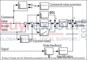
Adjustment to hydraulic system
For the optimum adjustment to the particularities of hydraulic drives, the following functions are implemented upstream the analog output:
Direction-dependent amplification [10] For positive and negative values, the amplification can be set separately. In this way, adjustment to the area ratio of a differential cylinder is possible. Characteristic curve correction [11] In this way, the progressive flow characteristics of proportional directional valves are compensated or an inflected characteristic curve is realized. Overlap jump/residual velocity [12] When using valves with positive overlap, a fine positioning can be used in case of a PDT1 controller in order to increase the static accuracy. This fine positioning can be selected according to the residual voltage principle and as overlap jump. Zero point correction (offset) [13] Serves the correction of the zero point of the connected proportional servo valve.
Error detection and treatment
The VT-HACD supports numerous error monitoring possibilities:
Monitoring of analog inputs for lower deviation or exceeding of the range Monitoring the position sensors for cable break Control error monitoring when configuring the HACD as controller Monitoring of the supply voltage, any internal voltage as well as the ±10 V reference voltage Monitoring the microcontroller (watchdog) as well as the memory (checksum)The error monitoring as well as its reaction can be configured as well.
Front operation
In connection with the four keys, the front display is used to display and change parameters as well as for diagnosis purposes.
The VT-HACD parameters are accessed via a corresponding menu structure. The parameter values can be displayed and changed.
The following parameters can be accessed:
Command value and ramp parameters Actual values Control parameters Output parameters Analog I/O Position sensorsChanges in the configuration, i.e. changes in the signal linking, trigger conditions, error monitoring, etc. are not possible via the front operation.
The display of command and actual values as well as the output of error messages are available as diagnosis options.
Valve output stage [18] (optional)
The following applies to the valve output stage:
Only available in connection with PROFIBUS Only for valves of type 4WRE…2X with two solenoids Can only be activated in mode 3Error logics identify a cable break of the actual value cable of the valve position transducer. Readiness for operation is removed, a low signal is output at connection d22 and the "OK" LED on the front plate goes out.
BODAC PC program
The BODAC PC program is used to configure, parameterize and diagnose the VT-HACD via a serial interface (RS 232). Via the local bus, up to 32 control electronics can be connected. Via BODAC, every control electronics is assigned a bus address. Reconnection of the serial interface cable is not required. More information in document 30143-01-B.
Related Products
R961001589
$94.01 USD
R961010273
$102.18 USD
1817010363
$129.88 USD
R961000741
$62.76 USD
R900887924
$101.48 USD


