


40 FLDN 0630 PWR3-A00-07V22-S0V0A
Manufacturer: Bosch Rexroth
Material #: R928000418
Model : 40 FLDN 0630 PWR3-A00-07V22-S0V0A
***Disclaimer: The following summary contains information gathered from various sources such as product descriptions, technical specifications and catalogs. While efforts have been made to provide accurate details, inaccuracies may occur. It is advised to verify all information by contacting Bosch Rexroth directly.***
The Bosch Rexroth 40 FLDN 0630 PWR3-A00-07V22-S0V0A (R928000418) is a high-performance duplex filter designed for inline hydraulic applications, ensuring the cleanliness of hydraulic fluids by efficiently filtering out very fine particles. This robust filter system includes two filter housings, each containing a filter element and connected by a switchover fitting that allows for seamless transitioning between the elements using a switching lever. The design is optimized to handle pressure peaks that can occur in dynamic hydraulic systems, particularly during sudden valve openings.
The unit is equipped with mechanical optical maintenance indicators as standard, which provide visual alerts when maintenance is required. These indicators also feature a memory function for enhanced monitoring. For more sophisticated monitoring, electronic switching elements can be added; these are available with one or two switching points and can be connected via connectors compliant with IEC standards or cable connections in accordance with EN standards.
The filter's construction includes bleed screws or valves (ordering code E) to facilitate maintenance activities such as bleeding air from the system during element exchange. Additional convenience features include floor mounting brackets for certain sizes and a standard pressure equalization line to assist in filling and bleeding processes.
Optional equipment for the Bosch Rexroth 40 FLDN 0630 PWR3-A00-07V22-S0V0A includes various electrical switching elements and an integrated bypass valve within the filter housing, further enhancing its versatility and functionality. The inlet and outlet ports are arranged with the inlet above and outlet below to support efficient fluid dynamics within hydraulic circuits. This specialized filtration solution offers exceptional dirt holding capacity across a wide range of pressure differentials, making it suitable for diverse applications requiring reliable inline filtration.
| Qty | Price | Savings |
|---|---|---|
| 5+ | $0.00 USD | $0.00 USD |
This product is not available. CLICK HERE to create a support ticket for us to locate your part or a suitable replacement
Function, section: NG0400 … 0630 / 0120
The 40FLD(N) duplex filter is suitable for inline installation. It basically consists of two filter housings (2) with one switch-over fitting (1), two filter covers (3), two filter elements (4) as well as mechanical optical maintenance indicator (8).
Via the inlet, the hydraulic fluid reaches the filter element (4) where it is cleaned. The dirt particles filtered out collect in the filter element (4). Via the outlet, the filtered fluid enters the hydraulic circuit.
Switching between the two filter housings is carried out by means of the switching lever.
The filter housing and all connection elements are designed so that pressure peaks – as they may occur e.g. in case of abrupt opening of large control valves due to the accelerated fluid quantity – can be securely absorbed.
Via the bleed screws (standard) and/or bleed valves – amending ordering code E – (7) the filter side to be maintained can be bled.
The sizes 0400-0630 / 0120 are equipped with mounting brackets. The standard pressure equalization line (10) serves to simplify the filling and bleeding in a filter element exchange.
By default, the filter is equipped with mechanical optical maintenance indicator (8). The electronic switching element (9) which has to be ordered separately is attached to the mechanical optical maintenance indicator (8) and held by means of a locking ring.
The electronic switching elements with 1 or 2 switching points are connected via a mating connector according to IEC-60947-5-2 or via a cable connection according to EN17301-803.

|
5 |
Draining dirt side |
|
6 |
Draining clean side |
Function, section: NG1001 / 0201 … 0271
The 40 FLD(N) duplex filter is suitable for inline installation. It basically consists of two filter housings (2) with one switch-over fitting (1), two threaded filter heads (3), two filter elements (4) as well as mechanical optical maintenance indicator (8).
Via the inlet, the hydraulic fluid reaches the filter element (4) where it is cleaned. The filtered dirt particles collect in the filter element (4) and the filtered fluid enters the hydraulic circuit via the outlet.
Switching between the two filter housings is carried out by means of the switching lever. The rotation limitation must be placed at the stop position.
The filter housing and all connection elements are designed so that pressure peaks – as they may occur e.g. in case of abrupt opening of large control valves due to the accelerated fluid quantity – can be securely absorbed.
Via the bleed screws (standard) and/or bleed valves – amending ordering code E – (7) the filter side to be maintained can be bled.
The sizes 1001 / 0201-0271 are equipped with a floor mount. The standard pressure equalization line (10) serves to simplify the filling and bleeding in a filter element exchange.
By default, the filter is equipped with mechanical optical maintenance indicator (8). The electronic switching element (9) which has to be ordered separately is attached to the mechanical optical maintenance indicator (8) and held by means of a locking ring.
The electronic switching elements with 1 or 2 switching points are connected via a mating connector according to IEC-60947-5-2 or via a cable connection according to EN17301-803.

|
5 |
Draining dirt side |
|
6 |
Draining clean side |
Filter element (measured with mineral oil HLP46 according to DIN 51524)
Spec. weight: < 0.9 kg/dm3
Δp-Q characteristic curves for complete filter, recommended initial Δp for design = 0,8 bar
Selection of the perfect filter is made possible by our online “Bosch Rexroth FilterSelect“ design software.
40FLDN0400-H3XL

40FLDN0630-H3XL

40FLDN1001-H3XL

40FLD0120-H3XL

40FLD0201-H3XL

40FLD0271-H3XL

40FLD0272-H3XL

40FLD0273-H3XL

40FLD0274-H3XL

40FLDN0400-H10XL

40FLDN0630-H10XL

40FLDN1001-H10XL

40FLD0120-H10XL

40FLD0201-H10XL

40FLD0271-H10XL

40FLD0272-H10XL

40FLD0273-H10XL

40FLD0274-H10XL


Size 0400 … size 0630, size 0120
Dimensions in mm

|
Type |
Height |
Widths |
Ports |
Fastening |
||||||||||
|
A1 |
A2 |
A3 1) |
A4 |
B1 |
⌀B2 |
⌀B3 |
B4 |
C1 |
ØD1 |
D2 |
D3 |
D4 |
D5 |
|
|
mm |
mm |
mm |
mm |
mm |
mm |
mm |
mm |
mm |
mm |
mm |
mm |
mm |
||
| 40FLDN0400 | 471 | 200 | 250 | 135 | 430 | 220 | 168.3 | 120 | SAE 3", 3000 psi | 17 | 220 | 110 | 130 | 6 |
| 40FLDN0630 | 621 | 350 | 400 | 370 | ||||||||||
| 40FLD0120 | 978 | 707 | 760 | 587 | 250 | |||||||||
| 1) | Servicing height for filter element exchange |
Size 0201 … size 0271, size 1001
Dimensions in mm

|
Type |
Height |
Widths |
Ports |
Fastening |
|||||||||
|
A1 |
A2 |
A3 1) |
A4 |
B1 |
⌀B2 |
B4 |
C1 |
ØD1 |
D2 |
D3 |
D4 |
D5 |
|
|
mm |
mm |
mm |
mm |
mm |
mm |
mm |
mm |
mm |
mm |
mm |
mm |
||
| 40FLD0201 | 1280 | 300 | 760 | 160 | 600 | 216 | 148 | SAE 4", 3000 psi | 23 | 200 | 260 | 120 | 15 |
| 40FLD0271 | 1522 | 990 | |||||||||||
| 40FLDN1001 | 930 | 400 | |||||||||||
| 1) | Servicing height for filter element exchange |
Size 0272
Dimensions in mm

|
Type |
Height |
Widths |
Ports |
Fastening |
|||||||||||||
|
A1 |
A2 |
A3 1) |
A4 |
A5 |
A6 |
B1 |
B2 |
B3 |
B5 |
B6 |
B7 |
C1 |
D2 |
D3 |
ØD4 |
G |
|
|
mm |
mm |
mm |
mm |
mm |
mm |
mm |
mm |
mm |
mm |
mm |
mm |
mm |
mm |
mm |
|||
| 40FLD00272 | 1590 | 375 | 1100 | 160 | 180 | 188 | 1347 | 559 | 262.5 | 547.5 | 148 | 285 | SAE 4", 3000 psi | 200 | 120 | 23 | G1/2 |
| 1) | Servicing height for filter element exchange |
Size 0273
Dimensions in mm

|
Type |
Height |
Widths |
Ports |
Fastening |
||||||||||||||
|
A1 |
A2 |
A3 1) |
A4 |
A5 |
A6 |
B1 |
B2 |
B3 |
B4 |
B5 |
B6 |
B7 |
C1 |
D2 |
D3 |
ØD4 |
G |
|
|
mm |
mm |
mm |
mm |
mm |
mm |
mm |
mm |
mm |
mm |
mm |
mm |
mm |
mm |
mm |
mm |
|||
| 40FLD00273 | 1590 | 375 | 1100 | 160 | 180 | 188 | 2066 | 559 | 262.5 | 612 | 897 | 148 | 285 | SAE 4", 3000 psi | 200 | 120 | 23 | G1/2 |
| 1) | Servicing height for filter element exchange |
Size 0274
Dimensions in mm

|
Type |
Height |
Widths |
Ports |
Fastening |
|||||||||||||||
|
A1 |
A2 |
A3 1) |
A4 |
A5 |
A6 |
B1 |
B2 |
B3 |
B4 |
B5 |
B6 |
B7 |
B8 |
C1 |
D2 |
D3 |
ØD4 |
G |
|
|
mm |
mm |
mm |
mm |
mm |
mm |
mm |
mm |
mm |
mm |
mm |
mm |
mm |
mm |
mm |
mm |
mm |
|||
| 40FLD0274 | 1590 | 375 | 1100 | 160 | 180 | 188 | 2066 | 822 | 262.5 | 612 | 897 | 148 | 285 | 285 | SAE 4", 3000 psi | 200 | 120 | 23 | G1/2 |
| 1) | Servicing height for filter element exchange |
Mating connectors for sensors and valves with connector “K24”, “K35” and “K72”, M12 x 1, with assembled connection line, cable shielded
4P M12 +
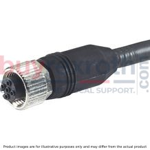
Mating connectors for sensors and valves with connector “K24”, “K35” and “K72”, M12 x 1, with assembled connection line, cable shielded
4P M12 +
For sensors and valves with connector “K24”, “K35” and “K72” Cable sets M12, 4-pole, line cross-section 0.34 mm2Data sheet
Spare parts & repair
Electronic switching elements
WE-.SP
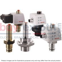
Electronic switching elements
WE-.SP
Operating temperature -30 … +85 °CData sheet
Spare parts & repair
Pressure differential indicators for filters in pressure lines
WO-D01
Pressure differential indicators for filters in pressure lines
WO-D01
Max. operating pressure 450 bar Operating temperature -30 … +100 °CData sheet
Spare parts & repair
Directives and standardization
Classification according to the Pressure Equipment Directive
The duplex filters for hydraulic applications according to 51408 are pressure holding equipment according to article 1, section 2.1.4 of the Pressure Equipment Directive 97/23/EC (PED). However, based on the exception in article 1, section 3.6 of the PED, hydraulic filters are exempt from the PED if they are not classified higher than category I (guideline 1/19).
The fluids from the chapter “Compatibility with approved pressure fluids” were considered for the classification.
They do not receive a CE mark.
Use in potentially explosive areas according to directive 94/9/EC (ATEX)
The duplex filters according to 51408 are not equipment or components in the sense of directive 94/9/EC and are not provided with a CE mark. It has been proven with the ignition risk analysis that these inline filters do not have own ignition sources acc. to DIN EN 13463-1:2009.
According to DIN EN 60079-11:2012, electronic maintenance indicators with a switching point:
WE-1SP-M12x1 R928028409
WE-1SP-EN175301-803 R928036318
are simple, electronic operating equipment that do not have an own voltage source. This simple, electronic operating equipment may – according to DIN EN 60079-14:2012 – in intrinsically safe electric circuits (Ex ib) be used in systems without marking and certification.
The duplex filters and the electronic maintenance indicators described here can be used for the following explosive areas:
|
Zone suitability |
||
|
Gas |
1 |
2 |
|
Dust |
21 |
22 |
Complete filter with mech./opt. maintenance indicator
|
Use/assignment |
II 2G | II 2D | ||
|
Assignment |
Ex II 2G c IIC TX | Ex II 2D c IIC TX | ||
|
Minimum conductivity of the medium |
pS/m |
300 | ||
|
Dust accumulation |
max. |
mm |
- | 0.5 |
Electronic switching element in the intrinsically safe electric circuit
|
Use/assignment |
II 2G | II 2D | ||
|
Assignment |
Ex II 2G Ex ib IIB T4 Gb | Ex II 2D Ex ib IIIC T100°C Db | ||
|
Perm. intrinsically safe electric circuit |
Ex ib IIC, Ex ic IIC | Ex ib IIIC | ||
|
Switching voltage Ui |
max. |
V AC/DC |
150 | |
|
Switching current Ii |
max. |
A |
1 | |
|
Switching power Pi |
max. |
1.3 W T4 Tmax 40 °C 1.0 W T4 Tmax 80 °C |
750 mW Tmax 40 °C 550 mW Tmax 100 °C |
|
|
Maximum surface temperature |
°C |
- | 100 1) | |
|
Inner capacity Ci |
neglectable | |||
|
Inner inductivity Li |
neglectable | |||
|
Dust accumulation |
max. |
mm |
- | 0.5 |
| 1) | The temperature depends on the temperature of the medium in the filter and must not exceed the value specified here. |
Possible circuit according to DIN EN 60079-14

WARNING!
Explosion hazard due to high temperature! The temperature depends on the temperature of the medium in the hydraulic circuit and must not exceed the value specified here. Measures are to be taken so that in the potentially explosive area, the max. admissible ignition temperature is not exceeded. When using the duplex filters according to 51408 in explosive areas, sufficient potential equalization has to be ensured. The filter is preferably to be grounded via the mounting screws. It has to be noted in this connection that painted and oxidized protective layers are not electrically conductive. During filter element exchanges, the packaging material is to be removed from the replacement element outside the explosive area.


