


4WRPNH6C3B40L-2X/M/24FA6T
Manufacturer: Bosch Rexroth
Material #: R901302671
Model : 4WRPNH6C3B40L-2X/M/24FA6T
***Disclaimer: The following summary contains information gathered from various sources such as product descriptions, technical specifications and catalogs. While efforts have been made to provide accurate details, inaccuracies may occur. It is advised to verify all information by contacting Bosch Rexroth directly.***
The Bosch Rexroth 4WRPNH6C3B40L-2X/M/24FA6T (R901302671) is a state-of-the-art high-response directional valve, equipped with integrated digital axis control (IACR) for precise motion control in hydraulic systems. This direct-operated valve features a control spool and sleeve of servo quality, ensuring reliable and accurate performance. It is designed to facilitate position control with an underlying velocity control and offers DSC functionality.
The valve's advanced design includes an analog sensor interface for current and voltage, as well as digital sensor interfaces that support various length measurement systems such as 1x length measurement system 5Vpp, SSI, or EnDat 2.2. Additionally, the product boasts clock-synchronized command value presetting in line with the PROFIdrive profile V4.1 and supports Telegram 401 or 402 for seamless integration into PROFIBUS DPV1 and DPV2 networks.
For diagnostics and parameterization, the Bosch Rexroth valve can be interfaced with the WinHPT commissioning software, which offers user-friendly data management on PCs running Windows 7 or Windows XP operating systems. The software simplifies project planning tasks and streamlines the setup process for optimal performance.
With a size of 6, component series X, maximum operating pressure of up to 315 bar, and maximum flow capacity of up to 40 l/min, this high-response valve is engineered to deliver robust performance in demanding applications. Its integrated electronics facilitate error detection such as cable breakage, undervoltage conditions, temperature monitoring of the electronics, communication errors, watchdog function, and synchronous monitoring.
Additional functionalities include error output at 24 V or control of an isolator valve, actuating variable adaptation, dead band compensation, zero point correction, valve inflection compensation, friction compensation with direction-dependent amplification along with PIDT controller settings and state controller options. The device also supports automatic or semi-automatic drive measurement for simplified controller optimization.
| Qty | Price | Savings |
|---|---|---|
| 5+ | $0.00 USD | $0.00 USD |
This product is not available. CLICK HERE to create a support ticket for us to locate your part or a suitable replacement
This product is eligible for factory repair.
Set-up
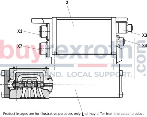
The IAC-R valve basically consists of:
direct operated high-response valve (1) with control spool and sleeve in servo quality integrated digital axis controller (2) with analog (X4/X7) or digital (X7) sensor interface PROFIBUS interface (X3) with functionality according to DP/V1 and clock synchronization according to DP/V2
Functional description
The IAC-R valve is a digital high-response valve with integrated axis controller and the following functionalities:
Position control DSC functionality analog (X4/X7) or digital (X7) sensor interface clock-synchronized command value presetting according to PROFIdrive profile V4.0 Telegram 5 or 105 The controller parameters are set via the PROFIdrive parameter protocol Separate supply voltage for bus/controller and power part (output stage) for safety reasons
The digital integrated control electronics enables the following error detection:
Cable break sensor technology Undervoltage Temperature of the integrated electronics Communication error Watchdog Synchronous monitoring
The following additional functions are available:
Error output 24 V or control of an isolator valve Actuating variable adaptation Dead band compensation Zero point correction Valve inflection compensation Friction compensation direction-dependent amplification PIDT1 controller State controller Automatic/semi-automatic drive measurement for easy controller optimization
WinHPT PC program
To implement the project planning task and to parameterize the IAC-R valves, the user may use the WinHPT commissioning software (see accessories):
Parameterization Diagnosis Comfortable data management on a PC PC operating systems: Windows 2000 or Windows XPHigh-response valve with integrated axis controller and analog (X4/X7) or digital (X7) interface
|
01 |
02 |
03 |
04 |
05 |
06 |
07 |
08 |
09 |
10 |
11 |
12 |
13 |
14 |
15 |
|||
|
4WRP |
N |
H |
B |
‒ |
2X |
/ |
M |
/ |
24 |
F |
* |
|
01 |
High-response valve, direct operated |
4WRP |
|
02 |
With integrated digital axis controller and NC functionality |
N |
|
03 |
Control spool/sleeve |
H |
|
04 |
Size 6 |
6 |
|
Size 10 |
10 |
|
|
05 |
Symbols; for the possible version, see "Symbols/Circuit diagrams" |
C, C1, C3, C4, C5 |
|
06 |
Installation side of the inductive position transducer 
|
B |
|
Rated flow at 70 bar valve pressure differential (35 bar/control edge) |
||
|
07 |
Size 6 |
|
|
2 l/min |
02 1) |
|
|
4 l/min |
04 |
|
|
12 l/min |
12 1) |
|
|
15 l/min |
15 2) |
|
|
24 l/min |
24 1) |
|
|
25 l/min |
25 2) |
|
|
40 l/min |
40 3) |
|
|
Size 10 |
||
|
50 l/min |
50 |
|
|
100 l/min |
100 |
|
|
Flow characteristic |
||
|
08 |
Linear |
L |
|
Inflected characteristic curve (inflection 60 % for NG6 with rated flows "15" and "25", otherwise inflection 40 %) |
P 4) |
|
|
09 |
Component series 20 ... 29 (20 ... 29: unchanged installation and connection dimensions) - Size 6 |
2X |
|
Seal material |
||
|
10 |
NBR seals Suitable for mineral oils (HL, HLP) according to DIN 51524 |
M |
|
11 |
Supply voltage 24 V |
24 |
|
Fieldbus interface |
||
|
12 |
PROFIBUS DP/V2 PROFIdrive Profil |
F |
|
Profibus DP V0/V1 |
P |
|
|
Electrical interface |
||
|
13 |
±10 VDC |
A6 |
|
4 ... 20 mA |
F6 |
|
|
Sensor interfaces |
||
|
14 |
X4, M12-5, ±10V; X7, M12-5, ±10V |
A |
|
X4, M12-5, ±10V; X7, M23-12, SSI 4) |
B |
|
|
X4, M12-5, ±10V; X7, M23-12, 1Vpp 5) |
C |
|
|
X4, M12-5, 4...20 mA; X7, M12-5, 4...20 mA |
G |
|
|
X4, M12-5, ±10 V; X7, M12-8, EnDat 2.2 |
T |
|
|
15 |
Further details in the plain text |
* |
|
1) |
Use only in connection with flow characteristics "L" |
|
|
2) |
Use only in connection with flow characteristics "P" |
|
|
3) |
qv 2:1 only with rated flow = 40 l/min |
|
|
4) |
Inflection 60 % for NG6 with rated flows "15" and "25", otherwise inflection 40 % |
|
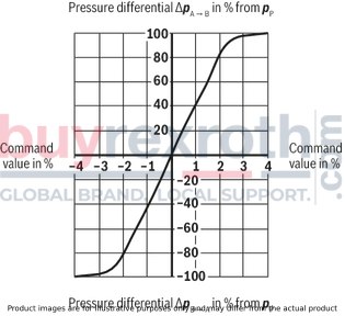
(measured with HLP46, ϑÖl = 40 ±5 °C)
Pressure amplification
NG6
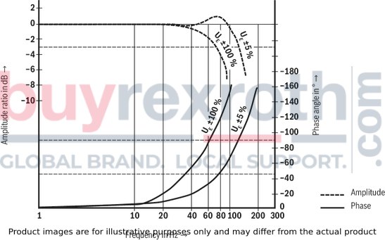
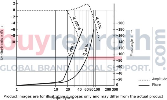
Frequency response
NG6
Linear characteristic curve “L”
NG6

Inflected characteristic curve "P", inflection at 60 %
NG6

Inflected characteristic curve "P", inflection at 40 %
NG6

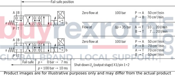
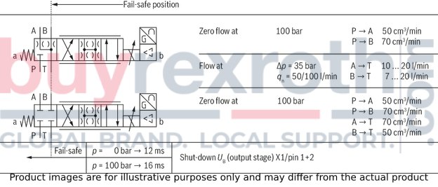
Fail-safe position
NG6
Pressure amplification
Size 10

Frequency response
Size 10
Linear characteristic curve "L" (1:1)
Size 10

Linear characteristic curve "L" (2:1)
Size 10

Inflected characteristic curve "P", inflection at 40 % (1:1)
Size 10

Inflected characteristic curve "P", inflection at 40 % (2:1)
Size 10

Fail-safe position
Size 10
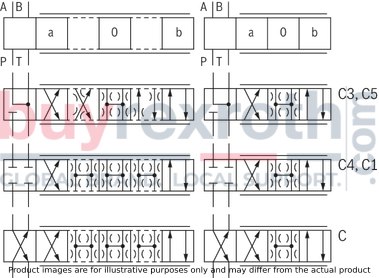
Symbols
|
With control symbol C1 and C5, the following applies: |
|
|
P → A: qvmax |
B → T: qv/2 |
|
P → B: qv/2 |
A → T: qvmax |
NG6

Size 10

|
Connector pin assignment X1, 11-pole + PE according to EN 175201-804 |
||
|
Pin |
Core marking 1) |
Assignment of interface A6/F6 |
|
1 |
1 |
24 VDC (supply for output stage and power circuit signal) |
|
2 |
2 |
0 V ≙ load zero, (for output stage) |
|
3 |
white |
reserved |
|
4 |
yellow |
reserved |
|
5 |
green |
reserved |
|
6 |
purple |
reserved |
|
7 |
pink |
reserved |
|
8 |
red |
reserved |
|
9 |
brown |
24 VDC (control voltage for signal part and bus) |
|
10 |
black |
0 V reference potential for pin 9 (supply of signal part and bus) |
|
11 |
blue |
Switching output 24 V (error signal or power circuit signal) max. 1.8 A |
|
PE |
green-yellow |
Protective earthing conductor (connected directly to metal housing) |
|
1) |
Core marking of the connection lines for mating connector with cable set |
|
|
Schirm nur auf der Versorgungsseite auf PE legen! |
||

|
Connector pin assignment for Profibus DP X3 (coding B), M12, 5-pole, socket/pins |
||
|
Pin |
Connector assignment |
Socket assignment |
|
1 |
n.c. |
VP |
|
2 |
RxD/TxD-N (A line) |
RxD/TxD-N (A line) |
|
3 |
D_GND |
D_GND |
|
4 |
RxD/TxD-P (B line) |
RxD/TxD-P (B line) |
|
5 1) |
Shield |
Shield |
|
1) |
We recommend connecting the shield on both sides via the metal housing of the plug-in connectors. Using pin 5 will affect the shielding effect! |
|
|
The device socket and connector are equivalent as PROFIBUS connections. The galvanically isolated voltage +5 V (pin1-VP) at the socket enables passive termination of the Profibus |
||

|
Analog sensor interfaces, port X4 and X7 (coding A), M12, 5-pole, socket |
||
|
Pin |
Assignment of voltage interface |
Assignment of current interface |
|
1 |
Supply 24 VDC |
Supply 24 VDC |
|
2 |
Signal 3 (X4) / 4 (X7), (-10 ... +10 V) |
Signal 3 (X4) / 4 (X7), (4 ... 20 mA) |
|
3 |
Zero 0 V |
Zero 0 V |
|
4 |
Signal 1 (X4) / 4 (X7), (-10 ... +10 V) |
Signal 1 (X4) / 4 (X7), (4 ... 20 mA) |
|
5 |
Shield |
Shield |
|
Attention: The analog sensor interfaces at ports X4 and X7 are not coded. Risk of confusion! The user must ensure correct wiring! |
||

|
Digital sensor interface 1 Vpp or SSI measurement system X7, M23, 12-pole, socket |
||
|
Pin |
Assignment 1 Vpp |
Assignment SSI |
|
1 |
B |
0 V |
|
2 |
Sense +5 V 1) |
Data |
|
3 |
R |
Clock |
|
4 |
R |
n.c. |
|
5 |
A |
n.c. |
|
6 |
A |
n.c. |
|
7 |
n.c. |
n.c. |
|
8 |
B |
n.c. |
|
9 |
n.c. |
24 V |
|
10 |
0 V 1) |
Data |
|
11 |
Sense 0 V 1) |
Clock |
|
12 |
+5 V 1) |
n.c. |
|
1) |
Recommendation:For encoder supply, connect voltages +5 V (pin 12) and +5 V sense (pin 2) as well as 0 V (pin 10) and 0 V sense (pin 11) |
|
|
Notice:The sense signal is not evaluated |
||

|
Digital sensor interface SSI, EnDat 2.2 measurement system "X7", M12, 8-pole, socket |
|
|
Pin |
Assignment EnDat 2.2 |
|
1 |
0 V 1) |
|
2 |
+5 V 1) |
|
3 |
Data + |
|
4 |
Data - |
|
5 |
0 V 1) |
|
6 |
Clock - |
|
7 |
Clock + |
|
8 |
supply +5 V 1) |
|
1) |
Recommendation:For encoder supply, connect voltages +5 V (pin 2 and 8) as well as 0 V (pin 1 and 5) |
|
We recommend connecting the shield on both sides via the metal housing of the plug-in connectors. Using pin 5 will affect the shielding effect! |
|


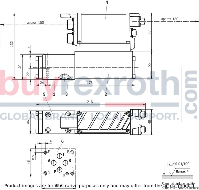
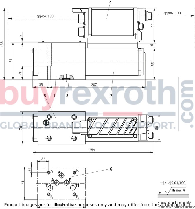
NG6
Dimensions in mm
|
1 |
Valve housing |
|
2 |
Control solenoid with position transducer |
|
3 |
Identical seal rings for ports A, B, P, and T |
|
4 |
Integrated digital control electronics |
|
5 |
Name plate |
|
6 |
Machined valve contact surface; Porting pattern according to ISO 4401-03-02-0-05 |
Recommended valve mounting screws (separate order):
4 hexagon socket head cap screws ISO 4762 - M5 x 30 - 10.9-N67F 821 70 (galvanized according to Bosch standard N67F 821 70)Tightening torque MA = 6+2Nm, material no. 2910151166
Size 10
Dimensions in mm
|
1 |
Valve housing |
|
2 |
Control solenoid with position transducer |
|
3 |
Identical seal rings for ports A, B, P and T (T1) |
|
4 |
Integrated digital control electronics |
|
5 |
Name plate |
|
6 |
Machined valve contact surface; Porting pattern according to ISO 4401-05-04-0-05 |
Recommended valve mounting screws (separate order):
4 hexagon socket head cap screws ISO 4762 - M6 x 40 - 10.9-N67F 821 70 (galvanized according to Bosch standard N67F 821 70)Tightening torque MA = 11+3 Nm, material no. 2910151209
Mating connectors for valves with round connector, 11-pole + PE
12P N11
Mating connectors for valves with round connector, 11-pole + PE
12P N11
For valves with round connector according to EN 175201-804, 11-pole + PEData sheet
Spare parts & repair
Related Products
R901319104
$2,919.00 USD
R901370949
$7,927.00 USD
R901478153
$6,479.00 USD
R901204540
$8,370.00 USD
R900957471
$13,104.00 USD


