


VANE PUMP PV7-1X/06-14RA01MA0-10-A473
Manufacturer: Bosch Rexroth
Material #: R901235918
Model : PV7-1X/06-14RA01MA0-10-A473
***Disclaimer: The following summary contains information gathered from various sources such as product descriptions, technical specifications and catalogs. While efforts have been made to provide accurate details, inaccuracies may occur. It is advised to verify all information by contacting Bosch Rexroth directly.***
The Bosch Rexroth PV7-1X/06-14RA01MA0-10-A473 (R901235918) is a high-performance variable displacement vane pump designed for demanding industrial applications in open circuit systems. It offers exceptional reliability, efficiency, and a low noise profile, making it suitable for environments where quiet operation is critical. The pump features a maximum pressure of bar and operates within a speed range of min to max rpm, delivering a maximum flow rate that aligns with its size cm³ displacement.
This model operates with a clockwise rotation and is constructed without through-drive capabilities. Its weight is carefully calibrated to ensure stability and ease of installation. The PV7-1X/06-14RA01MA0-10-A473 employs NBR seals and is compatible with hydraulic fluids such as HLP, HLPD, HVLP, and HVLPD.
Bosch Rexroth's design includes robust components like the housing, cover, rotor, vanes, stator ring, compression spring, set screw, and control plate. This design ensures minimal flow pulsation and high repetition accuracy with controlled pressure peaks. A key feature of this pump is its quick response behavior due to the adjustable displacement mechanism controlled by the set screw for precise flow limitation.
The innovative design also contributes to energy efficiency by maintaining operating pressure while minimizing power loss and heat generation through effective leakage compensation. With hydrodynamically lubricated plain bearings incorporated into its structure, this pump promises an extended lifecycle even under strenuous conditions.
Overall, the Bosch Rexroth PV7-1X/06-14RA01MA0-10-A473 variable displacement pump stands out for its very short control times, low operating noise levels, adherence to VDMA and ISO standards for mounting and connection dimensions, excellent efficiency rates, and variable displacement feature tailored for specific application needs within industrial settings.
This product is not available. CLICK HERE to create a support ticket for us to locate your part or a suitable replacement
This product is eligible for factory repair.
Variable displacement pump, size 14 cm³, pressure 70 bar for industrial applications, open circuit
High reliability. Low noise and low pulsation level. High efficiency. Quick response behavior of the controller.
Unpacked Weight: 5.22 kg
Very short control times Low operating noise Mounting and connection dimensions according to VDMA 24560/1 and ISO 3019-2 Good efficiency Long life cycle Variable displacement
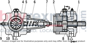
Hydraulic pumps of type PV7...A are direct operated vane pumps with adjustable displacement.
They basically comprise of housing (1), cover (2), rotor (3), vanes (4), stator ring (5), compression spring (6), set screw (7) and control plate (8).
For limitation of the maximum flow, the pump is equipped with a set screw (9).
The driven rotor (3) rotates within the stator ring (5). The centrifugal force presses the vanes (4) guided in the rotor (3) against the internal sliding surfaces of the stator ring (5).
Suction and displacement procedure
The cells (10) necessary to transport the hydraulic fluid are formed by the vanes (4), the rotor (3), the stator (5), the control plate (8) and the cover (2).
The cell volume increases by the rotation of the rotor (3) and via the suction channel (S), the cells (10) are filled with hydraulic fluid. When the largest cell volume is achieved, the cells (10) are separated from the suction side.
If the rotor (3) is rotated further, connection to the pressure side is established, the cells narrow and displace the hydraulic fluid via the pressure channel (P) into the system.
Pressure control
The stator ring (5) is held in the eccentric initial position by the spring (6). The maximum operating pressure required in the system is set at the set screw (7) using the spring (6).
The pressure building up by the load resistance acts at the pressure side on the inner sliding surface of the stator ring (5), against the force of the spring (6).
If the pressure corresponding to the set spring force has been reached, the stator ring (5) is pushed out of its eccentricity in zero position direction. The flow settles at the set value which is just removed. If the peak pressure set at the spring (6) is reached, the pump controls the flow to almost zero. The operating pressure is maintained and only the leakage is replaced. In this way, the power loss and heating of the hydraulic fluid are kept to a minimum.
PV7-1X/06…A…
PV7-2X/20…A…

Thanks to their specific design, PV7-type vane pumps with adjustable displacement boast low flow pulsation and achieve very high repetition accuracies with low pressure peaks during the down control. The noise optimization achieved by adjusting the height adjustment screw provides for a low operating noise. Hydrodynamically lubricated plain bearings ensure a long life cycle.
PV7‒../06-10
PV7‒../06-10....A0-05...

PV7‒../06-10....A0-10...

Sound pressure level

Notice
Characteristic curves measured with n = 1450 min-1; ν = 41 mm2/s; θ = 50 °C
Sound pressure level measured in the sound measuring chamber according to DIN 45635, sheet 26; distance: Microphone ‒ Pump = 1 m
PV7‒../06-14
PV7‒../06-14....A0-04...

PV7‒../06-14....A0-07...

Sound pressure level

Notice
Characteristic curves measured with n = 1450 min-1; ν = 41 mm2/s; θ = 50 °C
Sound pressure level measured in the sound measuring chamber according to DIN 45635, sheet 26; distance: Microphone ‒ Pump = 1 m
PV7‒../20-20
PV7‒../20-20....A0-05...

PV7‒../20-20....A0-10...

Sound pressure level

Notice
Characteristic curves measured with n = 1450 min-1; ν = 41 mm2/s; θ = 50 °C
Sound pressure level measured in the sound measuring chamber according to DIN 45635, sheet 26; distance: Microphone ‒ Pump = 1 m
PV7‒../20-25
V7‒../20-25....A0-05...

V7‒../20-25....A0-10...

Sound pressure level

Notice
Characteristic curves measured with n = 1450 min-1; ν = 41 mm2/s; θ = 50 °C
Sound pressure level measured in the sound measuring chamber according to DIN 45635, sheet 26; distance: Microphone ‒ Pump = 1 m

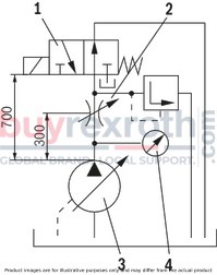
The control times apply to the shown measurement set-up.
With different set-ups and other line lengths, the control times change, as well.
Circuit diagram
|
1 |
Directional valve (switching time duration 30 ms) |
|
2 |
Throttle for setting the pressure during displacement |
|
3 |
Hydraulic pump |
|
4 |
pressure tapping point |
Down control
qv displacement → qv zero stroke

|
Pump type |
Pressure |
Control times (average) |
||
|
pnbar |
pmax 1) |
t1 down |
t2 down |
|
|
06-10...10 |
100 bar |
150 bar |
85 |
90 |
|
06-10...05 |
50 bar |
130 bar |
70 |
110 |
|
06-14...07 |
70 bar |
130 bar |
80 |
100 |
|
06-14...04 |
40 bar |
100 bar |
65 |
90 |
|
20-20...10 |
100 bar |
170 bar |
80 |
125 |
|
20-25...10 |
100 bar |
170 bar |
80 |
125 |
|
20-25...05 |
50 bar |
120 bar |
60 |
85 |
| 1) | Admissible pressure peaks |
Up control
qv zero stroke → qv displacement

|
Pump type |
Pressure |
Control times (average) |
|
|
pnbar |
t1 up |
t2 up |
|
|
06-10...10 |
100 bar |
35 |
60 |
|
06-10...05 |
50 bar |
20 |
30 |
|
06-14...07 |
70 bar |
30 |
50 |
|
06-14...04 |
40 bar |
20 |
35 |
|
20-20...10 |
100 bar |
25 |
45 |
|
20-25...10 |
100 bar |
25 |
45 |
|
20-25...05 |
50 bar |
20 |
40 |
PV7-../06
Dimensions in mm

|
1 |
Flow control |
|
2 |
Pressure adjustment by means of set screw (standard), ordering code ...0... |
|
3 |
Lock (optional), ordering code ...3... |
|
4 |
Space required to remove the key |
Ports
|
Denomination |
Size |
|
|
S |
Suction port |
G1/2 |
|
P |
Pressure port |
G3/8 |
|
L |
Leakage connection |
G1/4 |
Adjustment information
Flow control (1)
with clockwise rotation, reduction of the flow with counterclockwise rotation, increase in flowPressure adjustment (2)
with clockwise rotation, increase in the operating pressure with counterclockwise rotation, reduction of the operating pressurePV7-../20
Dimensions in mm

|
1 |
Flow control |
|
2 |
Pressure adjustment by means of set screw (standard), ordering code ...0... |
|
3 |
Lock (optional), ordering code ...3... |
|
4 |
Space required to remove the key |
Ports
|
Denomination |
Size |
|
|
S |
Suction port |
G3/4 |
|
P |
Pressure port |
G1/2 |
|
L |
Leakage connection |
G1/4 |
Adjustment information
Flow control (1)
with clockwise rotation, reduction of the flow with counterclockwise rotation, increase in flowPressure adjustment (2)
with clockwise rotation, increase in the operating pressure with counterclockwise rotation, reduction of the operating pressureFluid tank
Adjust useful volume of the tank to the operating conditions. The admissible fluid temperature must not be exceeded; use coolers, if necessary.
Lines and connections
Remove the protective plug at the pump. We recommend using seamless precision steel pipes according to DIN 2391 and releasable pipe connections. Select the inner width of the pipes according to the connections. Pipelines and fittings must be carefully cleaned before assembly.Proposal for piping layout
Minimum dimensions [mm]
 Lay the leakage line so that the pump cannot run empty! Leakage and return fluid must not be directly sucked in again under any circumstances!
Filter
Use a return flow or pressure filter, if possible.
(Suction filters only in connection with underpressure switch / clogging indicator).
Hydraulic fluid
Please observe our provisions according to data sheet 90220. We recommend brand hydraulic fluids Different hydraulic fluid types must not be mixed as this might result in degradation and deterioration of the lubricity. According to the operating conditions, the hydraulic fluid must be renewed at certain time intervals. In this connection, it is also necessary to clean the hydraulic fluid tank from residues.Drive
Electric motor + pump carrier + coupling + pump
 No radial and axial forces on the pump drive shaft admissible! Motor and pump must be exactly aligned! Use a torsionally flexible coupling.
Installation positions
Horizontal position preferred
B3

B5

V1
Related Products
R900945611
$1,469.00 USD
R901423309
$8,594.00 USD
R900086164
$1,046.00 USD
R901088869
$3,302.00 USD
R978005715
$2,328.00 USD


