


Manufacturer: Bosch Rexroth
Material #: R900978720
Model : DRE 6-1X/100MG24K4M-3
***Disclaimer: The following summary contains information gathered from various sources such as product descriptions, technical specifications and catalogs. While efforts have been made to provide accurate details, inaccuracies may occur. It is advised to verify all information by contacting Bosch Rexroth directly.***
The Bosch Rexroth DRE 6-1X/100MG24K4M-3 (R900978720) is a pilot-operated pressure reducing valve designed for precise control of system pressure through its advanced technical setup. This valve features three primary components: a pilot control valve, a proportional solenoid with integrated control electronics, and a main valve with a main control spool. It operates by adjusting the pressure in channel A via the proportional solenoid, depending on the command value received.
In its default state, the spring holds the main control spool in position to allow flow from A to T while blocking P to A. The pressure reduction function is activated by building pilot pressure in the control chamber as dictated by the command value, causing hydraulic fluid to flow from P to A. As port A's pressure reaches the set level of the pilot control valve, this triggers movement of the main control spool to balance out at the desired pressure.
Should port A's pressure exceed this set point, the DRE 6-1X/100MG24K4M-3 ensures safety through its pressure limitation feature by shifting the main control spool further left, establishing a connection from A to T and capping port A's pressure at the set command value.
This model is suitable for subplate mounting or sandwich plate design with porting patterns according to ISO standards. It offers minimal set pressures in ports A or P and includes type DREE valves with integrated electronics OBE for enhanced functionality. The component series X indicates its design series and it can handle maximum operating pressures up to bar and flows up to l/min, ensuring reliable performance across various applications.
This product is not available. CLICK HERE to create a support ticket for us to locate your part or a suitable replacement
This product is eligible for factory repair.
Valves of type DRE are electrically pilot-operated 3-way pressure reducing valves with pressure limitation of the actuator. They are used for reducing a system pressure.
Technical set-up:
The valve consists of three main assemblies:
Pilot control valve (1) Proportional solenoid (2) Main valve (3) with main control spool (4)Function:
General function:
Command value-dependent setting of the pressure to be reduced in channel A via the proportional solenoid (2). In the depressurized port P, the spring (17) holds the main control spool (4) in the initial position. Thus, opening the connection from A to T and blocking of the connection from P to A. Pressure connection from port P to the ring channel (5). Pilot oil flows from the bore (6) to port T, via the flow controller (7), the nozzle (8) to the pilot control valve (1), the throttle gap (9) to the longitudinal groove (10) and the bores (11, 12).Pressure reduction:
Build-up of the pilot pressure in the control chamber (16) as function of the command value. Movement of the main control spool (4) to the right, hydraulic fluid flows from P to A. Actuator pressure pending in port A to the spring chamber (15) via channel (13) and nozzle (14). Increase in the pressure in port A to the set pressure of the pilot control valve (1) leads to the movement of the main control spool (4) to the left. Pressure in port A is almost identical with the set pressure at the pilot control valve (1).Pressure limitation:
If the pressure in port A exceeds the set pressure of the pilot control valve (1), the main control spool (4) is moved further to the left. Thus, opening of the connection from A to T and limitation of the pressure pending in port A to the set command value.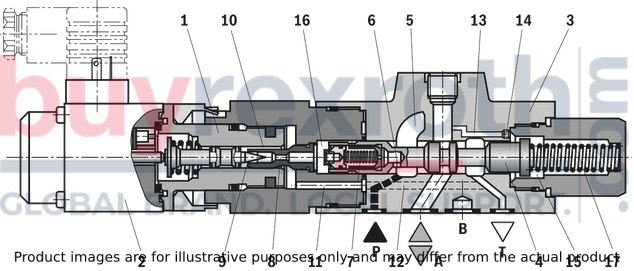
Valves of type DREE are electrically pilot-operated 3-way pressure reducing valves with pressure limitation of the actuator. They are used for reducing a system pressure.
Technical set-up:
The valve consists of three main assemblies:
Pilot control valve (1) Proportional solenoid (2) with control electronics (18) Main valve (3) with main control spool (4)Function:
General function:
Command value-dependent setting of the pressure to be reduced in channel A via the proportional solenoid (2). In the depressurized port P, the spring (17) holds the main control spool (4) in the initial position. Thus, opening the connection from A to T and blocking of the connection from P to A. Pressure connection from port P to the ring channel (5). Pilot oil flows from the bore (6) to port T, via the flow controller (7), the nozzle (8) to the pilot control valve (1), the throttle gap (9) to the longitudinal groove (10) and the bores (11, 12). Supply and command value voltage or command value current are applied to the connector (19). At the factory, the command value pressure characteristic curve is adjusted with little manufacturing tolerance.Pressure reduction:
Build-up of the pilot pressure in the control chamber (16) as function of the command value. Movement of the main control spool (4) to the right, hydraulic fluid flows from P to A. Actuator pressure pending in port A to the spring chamber (15) via channel (13) and nozzle (14). Increase in the pressure in port A to the set pressure of the pilot control valve (1) leads to the movement of the main control spool (4) to the left. Pressure in port A is almost identical with the set pressure at the pilot control valve (1).Pressure limitation:
If the pressure in port A exceeds the set pressure of the pilot control valve (1), the main control spool (4) is moved further to the left. Thus, opening of the connection from A to T and limitation of the pressure pending in port A to the set command value.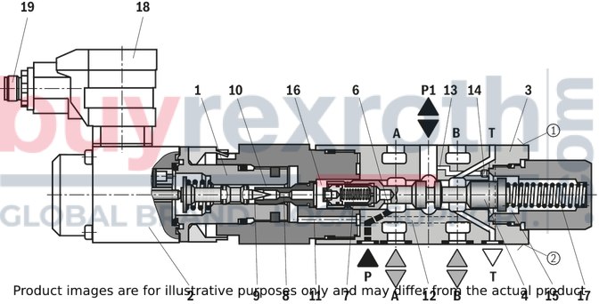
(measured with HLP46, ϑOil = 40 ±5 °C)
Pressure in port A dependent on the command value (manufacturing tolerance); without flow
(Z)DRE

| 1) | With type (Z)DRE, the manufacturing tolerance at the external amplifier can be adjusted using the command value attenuator potentiometer "Gw". With the digital amplifier, the setting is made using the "Limit" parameter. In this connection, the control current according to the technical data must not be exceeded! In order to match several valves to the same characteristic curve, at a command value of 100%, the pressure must not exceed the maximum set pressure of the relevant pressure rating at no valve. |
Type (Z)DRE: Pressure in port P1 or A dependent on the command value
Pressure rating 50 bar
(Z)DRE

Pressure rating 100 bar
(Z)DRE

Pressure rating 210 bar
(Z)DRE

Pressure rating 50 bar
(Z)DREE

Pressure rating 100 bar
(Z)DREE

Pressure rating 210 bar
(Z)DREE

Minimum set pressure in port P1 or A with command value 0 V
(without counter pressure in channel T)
Pressure rating 50 bar
(Z)DRE

Pressure rating 100 bar / 210 bar
(Z)DRE

Pressure in channel P1 or A – flow
Pressure rating 50 bar
(Z)DRE

Pressure rating 100 bar
(Z)DRE

Pressure rating 210 bar
(Z)DRE

Δp-qV characteristic curves
(Z)DRE

Δp-qV characteristic curves
(Z)DRE

Notice:
The indicated Δp value corresponds to the minimum pressure available in port P (P2) minus the maximum pressure to be controlled in port A (P1).
Type DRE 6...

Type DREE 6...
(Z)DREE 6...1X
|
Pin assignment |
Contact |
Assignment interface "A1" |
Assignment interface "F1" |
|
Power supply |
1 |
24VDC(u(t)= 21 ...35V);Imax ≤ 1,5 A |
|
|
Command value input |
2 |
0 ... 10 V; Re = 20 kΩ |
4 ... 20 mA; Re = 100 kΩ |
|
Reference potential actual value |
3 |
0 V |
|
|
Differential amplifier input (command value) |
4 |
Reference potential command value |
|
M12 plug-in connector port
Connector on amplifier

Mating connector and wire colors with pre-assembled cable set

Connection at the connector

Connection at mating connector

Connection cable
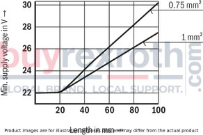
| 1) | Connection cable:- Recommendation 6-wire, 0.75 or 1mm2 plus protective earthing conductor and screening- Connect screening to PE on supply side only- Maximum admissible length 100 m The minimum supply voltage at the power supply unit depends on the length of the supply line (see diagram) |
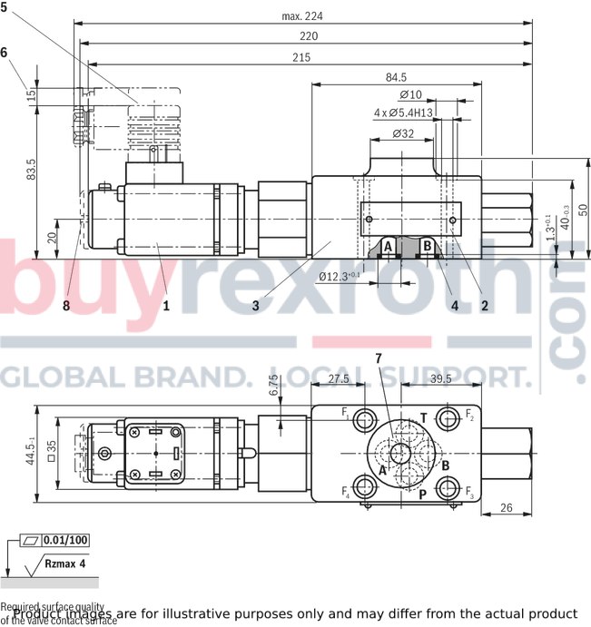
Type DRE 6...
Dimensions in mm
|
1 |
Proportional solenoid without manual override |
|
2 |
Name plate |
|
3 |
Valve housing |
|
4 |
Identical seal rings for ports A, B, P, and T |
|
5 |
mating connector according to DIN EN 175301-803 |
|
6 |
Space required to remove the mating connector |
|
7 |
Machined valve contact surface; Porting pattern according to ISO 4401-03-02-0-05 |
|
8 |
Proportional solenoid with manual override |
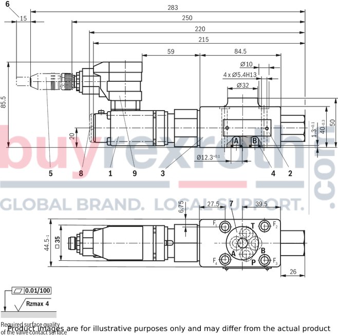
Type DREE 6...
Dimensions in mm
|
1 |
Proportional solenoid without manual override |
|
2 |
Name plate |
|
3 |
Valve housing |
|
4 |
Identical seal rings for ports A, B, P, and T |
|
5 |
mating connector according to DIN EN 175301-803 |
|
6 |
Space required to remove the mating connector |
|
7 |
Machined valve contact surface; Porting pattern according to ISO 4401-03-02-0-05 |
|
8 |
Proportional solenoid with manual override |
|
9 |
Integrated electronics (OBE) |
Notice:
The dimensions are nominal dimensions which are subject to tolerances.
Recommended valve mounting screws (separate order):
4 hexagon socket head cap screws ISO 4762 - M5 x 50 - 10.9-flZn-240h-L Tightening torque MA = 7 Nm ± 10%Mating connectors for valves with connector “K4”, without circuitry, standard
3P Z4

Mating connectors for valves with connector “K4”, without circuitry, standard
3P Z4
For valves with connector “K4” according to EN 175301-803 and ISO 4400, 2-pole + PE, “large cubic connector” Mating connectors for valves with one or two solenoids (individual connection)Data sheet
Spare parts & repair
Related Products
R900973353
$6,916.90 USD
R901416033
$11,697.00 USD
R900706613
$8,723.00 USD
R900765008
$10,630.00 USD
0811402639
$10,946.00 USD


