


PGH4-2X/040RE11VU2
Manufacturer: Bosch Rexroth
Material #: R900086321
Model : PGH4-2X/040RE11VU2
***Disclaimer: The following summary contains information gathered from various sources such as product descriptions, technical specifications and catalogs. While efforts have been made to provide accurate details, inaccuracies may occur. It is advised to verify all information by contacting Bosch Rexroth directly.***
The Bosch Rexroth PGH4-2X/040RE11VU2 (R900086321) is a high-quality hydraulic pump designed for efficient and reliable operation. This internal gear pump features gap compensation with a constant displacement, ensuring high efficiency even at low speeds and viscosities. Its robust construction includes a housing, bearing cover, internal gear, pinion shaft, plain bearings, axial washers, end cover, mounting flange, stop pin, and a segment filler element that comprises the segment, segment support, and seal rolls.
The pump operates by utilizing a hydrodynamically supported pinion shaft to drive the internal gear. It offers an increased volume in the suction range over an angle of approximately 180 degrees to facilitate fluid flow into the chambers. The unique design of the sickle-shaped segment filler element divides the suction and pressure chambers effectively. The axial compensation force ensures minimal longitudinal gaps between rotating and fixed parts for optimal sealing of the pressure chamber.
Radial compensation is achieved through forces acting on the segment filler elements dependent on operating pressure to maintain an almost leakage-free seal between internal gear, segment filler element, and pinion shaft. The involute tooth system of the gears contributes to low flow and pressure pulsation which in turn results in low operating noise.
The PGH4-2X/040RE11VU2 pump's hydrodynamic and hydrostatic mounting accommodates forces on both the pinion shaft through lubricated radial plain bearings and on the internal gear through hydrostatic bearing support. This pump is capable of handling broad viscosity and speed ranges with its fixed displacement design. It can be used in various configurations as it is compatible with all frame sizes and can be combined with other pumps such as internal gear pumps, radial piston pumps, and external gear pumps. With its maximum operating pressure bar rating and maximum displacement cm³/u specifications (not provided), this Bosch Rexroth hydraulic pump stands out for its versatility and performance in demanding applications.
This product is not available. CLICK HERE to create a support ticket for us to locate your part or a suitable replacement
This product is eligible for factory repair.
Set-up
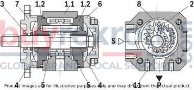
Hydraulic pumps of type PGH are gap-compensated internal gear pumps with constant displacement.
They basically comprise of housing (1.1), bearing cover (1.2), internal gear (2), pinion shaft (3), plain bearings (4), axial washers (5), end cover (6), mounting flange (7) and stop pin (8), as well as the segment filler element (9) consisting of segment (9.1), segment support (9.2) and the seal rolls (9.3).
Suction and displacement procedure
The hydrodynamically supported pinion shaft (3) drives the internally geared internal gear (2) in the displayed direction of rotation.
During the rotation, there is a volume increase over an angle of approx. 90° in the suction range. An underpressure results and fluid flows into the chambers.
The sickle-shaped segment filler element (9) separates suction and pressure chamber. In the pressure chamber, the teeth of the pinion shaft (3) engage in the space between the teeth of the internal gear (2) again. The liquid is displaced via the pressure channel (P).
Axial compensation
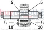
The axial compensation force FA takes effect in the area of the pressure chamber and is generated with the pressure field (10) in the axial washers (5).
So the axial longitudinal gaps between the rotating and the fixed parts are extraordinarily small and ensure perfect axial sealing of the pressure chamber.
Radial compensation

The radial compensation force FR acts on segment (9.1) and segment support (9.2).
Dependent on the operating pressure, the two segment filler elements (9.1) and (9.2) are pressed against the head diameters of pinion shaft (3) and internal gear (2).
The area ratios and the position of the seal rolls (9.3) between the segment and segment support are designed so that an almost leakage gap-free sealing between internal gear (2), segment filler element (9) and pinion shaft (3) is achieved.
Spring elements under the seal rolls (9.3) ensure sufficient contact pressure, also with very low pressures.
Hydrodynamic and hydrostatic mounting
The forces acting on the pinion shaft (3) are accepted by hydrodynamically lubricated radial plain bearings (4); the forces acting on the internal gear (2) by the hydrostatic bearing (11).
Gear tooth system
The toothing is an involute tooth system. Its large meshing length results in little flow and pressure pulsation; these little pulsation rates considerably contribute to the low-noise running.
PGH-type hydraulic pumps are gap-compensated internal gear pumps with fixed displacement. The hydrodynamically mounted pinion shaft drives the internal gear. The pinion shaft and internal gear tooth clearances opening in the suction range suck in the hydraulic fluid and transport it to the pressure range. The suction and pressure range are separated by the radial compensation elements and the tooth engagement between the internal gear and pinion shaft.
Average values of frame sizes 2 and 3
Flow

Efficiency

Drive power

Sound pressure level

Notice
Characteristic curves measured with n = 1450 min-1; ν = 41 mm2/s; θ = 50 °C Sound pressure level measured in the sound measuring chamber according to DIN 45635, sheet 26;Distance: Microphone ‒ pump = 1 m

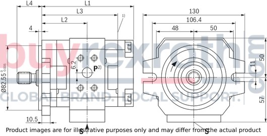
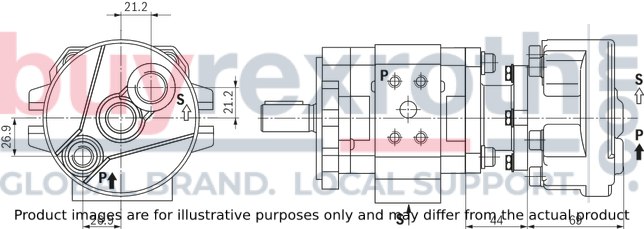
Frame size 2
With cylindrical shaft or splined shaft SAE J744 and SAE mounting flange 82‒2
Dimensions in mm
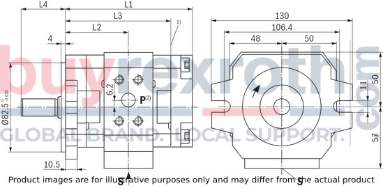
| 1) | With multiple pumps, the combination part will start from here |
| 2) | The figure shows pumps with clockwise rotation; with pumps with counterclockwise rotation, the pressure port is on the opposite side! |
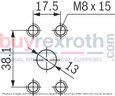
Partial view suction port S
Dimensions in mm

Partial view pressure port P
Dimensions in mm
|
Type |
Material numbers |
L1 |
L2 |
L3 |
L4 |
Suction port S 2) |
Pressure port P 2) |
||||
|
PGH2-2X/ |
005 |
R 1) |
E |
07VU2 |
R900968999 |
110 mm |
54,2 mm |
89,5 mm |
41 mm |
1/2 in 344,7 bar |
1/2 in 344,7 bar |
|
L |
R900703725 |
||||||||||
|
R 1) |
R |
07VU2 |
R900972378 |
31,5 mm |
|||||||
|
L |
R900703727 |
||||||||||
|
006 |
R 1) |
E |
07VU2 |
R900951301 |
112,5 mm |
55,5 mm |
92 mm |
41 mm |
1/2 in 344,7 bar |
1/2 in 344,7 bar |
|
|
L |
R900961547 |
||||||||||
|
R 1) |
R |
07VU2 |
R900961549 |
31,5 mm |
|||||||
|
L |
R900961550 |
||||||||||
|
008 |
R 1) |
E |
07VU2 |
R900951302 |
116 mm |
57,3 mm |
95,5 mm |
41 mm |
1/2 in 344,7 bar |
1/2 in 344,7 bar |
|
|
L |
R900961548 |
||||||||||
|
R 1) |
R |
07VU2 |
R900961551 |
31,5 mm |
|||||||
|
L |
R900961552 |
||||||||||
| 1) | Preferably available |
| 2) | Standard pressure series |
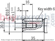
Cylindrical shaft with fitting key DIN 6885
Dimensions in mm
Splined shaft SAE J744
R - 16-4 (A) in 9T 16/32DP1)2)
Dimensions in mm

| 1) | Suitable as central and back pump for multiple pumps |
| 2) | Involute tooth system according to ANSI B92.1a, 30° pressure angle, flat root, side fit, tolerance class 5 |
Frame size 3
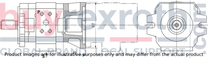
With cylindrical shaft and SAE mounting flange 101‒2
Dimensions in mm

| 1) | With multiple pumps, the combination part will start from here |
| 2) | The figure shows pumps with clockwise rotation; with pumps with counterclockwise rotation, the pressure port is on the opposite side! |
Partial view suction port S
Dimensions in mm

Partial view pressure port P
Dimensions in mm
|
Type |
Material numbers |
L1 |
L2 |
L3 |
L4 |
Suction port S 2) |
Pressure port P 2) |
||||
|
PGH3-2X/ |
011 |
R 1) |
E |
07VU2 |
R900951303 |
128 mm |
66,5 mm |
107,5 mm |
41 mm |
1 in 208,6 bar |
1/2 in 344,7 bar |
|
L |
R900961553 |
||||||||||
|
013 |
R 1) |
E |
07VU2 |
R900951304 |
133 mm |
69 mm |
112,5 mm |
41 mm |
1 in 208,6 bar |
1/2 in 344,7 bar |
|
|
L |
R900961554 |
||||||||||
|
016 |
R 1) |
E |
07VU2 |
R900951305 |
138 mm |
71,5 mm |
117,5 mm |
41 mm |
1 in 208,6 bar |
1/2 in 344,7 bar |
|
|
L |
R900961555 |
||||||||||
| 1) | Preferably available |
| 2) | Standard pressure series |
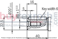
Cylindrical shaft with fitting key DIN 6885
Dimensions in mm
With splined shaft SAE J744 and SAE mounting flange 82‒2
Dimensions in mm
| 1) | With multiple pumps, the combination part will start from here |
| 2) | The figure shows pumps with clockwise rotation; with pumps with counterclockwise rotation, the pressure port is on the opposite side! |
Partial view suction port S
Dimensions in mm
Partial view pressure port P
Dimensions in mm
|
Type |
Material numbers |
L1 |
L2 |
L3 |
L4 |
Suction port S 2) |
Pressure port P 2) |
||||
|
PGH3-2X/ |
011 |
R 1) |
R |
07VU2 |
R900961556 |
121,5 mm |
60 mm |
101 mm |
31,5 mm |
1 in 206,8 bar |
1/2 in 344,7 bar |
|
L |
R900961559 |
||||||||||
|
R |
S |
07VU2 |
R901267181 |
37 mm |
|||||||
|
013 |
R 1) |
R |
07VU2 |
R900961557 |
126,5 mm |
62,5 mm |
106 mm |
31,5 mm |
1 in 206,8 bar |
1/2 in 344,7 bar |
|
|
L |
R900961560 |
||||||||||
|
R |
S |
07VU2 |
R901281697 |
37 mm |
|||||||
|
016 |
R 1) |
R |
07VU2 |
R900961558 |
131,5 mm |
65 mm |
111 mm |
31,5 mm |
1 in 206,8 bar |
1/2 in 344,7 bar |
|
|
L |
R900961561 |
||||||||||
|
R |
S |
07VU2 |
R901281698 |
37 mm |
|||||||
| 1) | Preferably available |
| 2) | Standard pressure series |
Splined shaft SAE J744
R - 16-4 (A) in 9T 16/32DP1)2)
Dimensions in mm
| 1) | Suitable as central and back pump for multiple pumps |
| 2) | Involute tooth system according to ANSI B92.1a, 30° pressure angle, flat root, side fit, tolerance class 5 |
S - 19-4 in 11T 16/32DP1)
Dimensions in mm

| 1) | Involute tooth system according to ANSI B92.1a, 30° pressure angle, flat root, side fit, tolerance class 5 |
Multiple pumps
All internal gear pumps of type PGH can be combined, every pump is equipped with an output gear tooth system. The combination possibilities and die material numbers of the required combination parts are available in the following table.
|
Back pump |
Front pump |
|
|
PGH2-2X |
PGH3-2X |
|
|
PGH2-2X/...R...U2 |
R900886137 |
R900886137 |
|
PGH3-2X/...R...U2 |
R900886137 |
R900886137 |
|
PGP2-2X/...J...U2 |
R900886137 |
R900886137 |
|
PGF2-2X/...J...U2 |
R900886137 |
R900886137 |
|
AZPF...RR...B |
R900886137 |
R900886137 |
|
PR4-1X...WA |
R900886137 |
R900886137 |
The dimensional drawings show the front pump and the combination part.1)
PGH2/PGH3
PGH2 with combination part for PGH2, PGH3, PGF2, PGP2, AZPF
Dimensions in mm
PGH2/PGH3 + R4-Mini
Dimensions in mm
| 1) Dimensions of the single pumps see Dimensions or the corresponding data sheets of the back pump. |
SAE connection flanges
Dimensions in mm

|
PGH |
Flange |
Material number1) for flange with |
Dimensioning |
|||||||||
|
Suction flange |
Pressure flange |
NG, pressure |
Welded connection |
Threaded connection 2) |
B1 |
B2 |
H1 |
H2 |
D1 |
D2 |
D3 |
D4 |
|
PGH2/005/ 006/008 |
PGH2/005/ 006/008 |
1/2 in 344,7 bar |
R900026298 |
R900024200 |
38,1 mm |
54 mm |
17,5 mm |
46 mm |
20 mm |
14 mm |
G1/2 |
M8 x 30 |
|
PGH3/011/013/016 |
– |
1 in 206,8 bar |
R900012937 |
R900014154 |
52,4 mm |
70 mm |
26,2 mm |
59 mm |
35 mm |
27 mm |
G1 |
M10 x 35 |
| 1) | The material numbers comprise the flange, the O-ring (NBR) and the mounting screws. |
| 2) | Pipe thread “G” according to DIN EN ISO 228/1 |
Pump safety block
For limitation of the operating pressure or (and) for the solenoid-actuated unloading of the operating pressure, we recommend our pump safety blocks according to data sheets 25880 and 25891.
Comprehensive information and suggestions are contained in the Hydraulics Trainer, volume 3 "Project planning information and design of hydraulic systems".
When using internal gear pumps, a manual, switchable or automatic bleeding option must moreover be provided. The bleeding point for manual bleeding must be provided in the pressure line in front of the first valve or check valve so that depressurized bleeding is possible.
Technical data
All specified technical data depend on production tolerances and are valid at certain boundary conditions.
Please note that consequently, fluctuations are possible and that with certain boundary conditions (e.g. viscosity), the technical data may also change.
Characteristic curves
When designing the drive motor, please observe the maximum application parameters possible shown by the presented characteristic curves.
Sound pressure level
The shown values for sound pressure level on characteristic curves have been measured based on DIN 45635, sheet 26.
That means that only the sound emission of the pump is shown. Environmental influences (place of installation, piping, etc.) have not been considered.
These values are in each case only valid for one pump.
With internal gear pumps, the excitation of valves, pipelines, machine parts, etc. is very low due to the little flow pulsation (approx. 2 to 3%).
With unfavorable influences, the sound pressure level at the place of installation of the power unit may, however, still be 5 to 10 db(A) higher than the values of the pump itself.
Multiple pump
The same general technical data apply as for single pumps (see Technical data). The combined pumps must all have the same direction of rotation. The pump with the largest torque should be intended as first pump. The maximum through-drive torque must be checked by the project planner for every application. This is also true for already existing (coded) multiple pumps. The total of the torques in a multiple pump must not exceed the maximum drive torque. Joint aspiration is not possible. Before operating pump combinations with different hydraulic fluids, please consult Bosch Rexroth. Medium and back pumps must be equipped with drive shafts version “R” (geared). The drive torque of a pump stage is calculated as follows:
|
Legende |
|
|
T |
Torque [Nm] |
|
Δp |
Operating pressure [bar] |
|
V |
Displacement [cm³] |
|
η |
Hydraulic-mechanical efficiency |
Maximum admissible torques [Nm]
|
Type |
Drive torque |
Drive torque |
||
|
Cyl. shaft E |
Splined shaft R |
Splined shaft S |
||
|
PGH2 |
100 |
80 |
155 |
75 |
|
PGH23 |
110 |
80 |
155 |
75 |

Fluid tank
Adjust useful volume of the tank to the operating conditions The admissible fluid temperature must not be exceeded; use coolers, if necessary.Lines and connections
Remove the protective plug at the pump. Select the inner width of the pipes according to the connections (suction speed 1 to 1.5 m/s). For the inlet pressure refer to the Technical data Pipelines and fittings must be carefully cleaned before assembly.Proposal for piping layout
Dimensions in mm
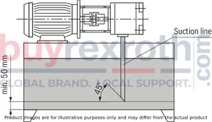 Return fluid must not be directly sucked in again under any circumstances, i.e. select the largest distance possible between suction and return line. Suction line and return flow outlet must always lie clearly below the oil level. Ensure suction-tight assembly of the pipelines.
Filter
Use return flow or pressure filter if possible.
(Only use suction filters in connection with underpressure switch / clogging indicator).
Hydraulic fluid
Please observe our provisions according to data sheet 90220. We recommend brand hydraulic fluids. Different hydraulic fluid types must not be mixed as this might result in degradation and deterioration of the lubricity. According to the operating conditions, the hydraulic fluid must be renewed at certain time intervals. In this connection, it is also necessary to clean the hydraulic fluid tank from residues.Drive
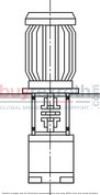
Electric motor + pump carrier + coupling + pump
 No radial and axial forces on the pump drive shaft admissible! Motor and pump must be exactly aligned! Always use a coupling that is suitable for compensating shaft displacements! Avoid axial forces when attaching the coupling, i.e. do not assemble it using impact tools or by pressing it on! Use an internal thread of the drive shaft!
Installation positions
B3

B5

V1
Related Products
R900212896
$819.00 USD
R900086160
$1,026.00 USD
R901018122
$2,858.00 USD
R978913882
$3,389.00 USD
R901106500
$2,636.00 USD


